8
ENGLISH
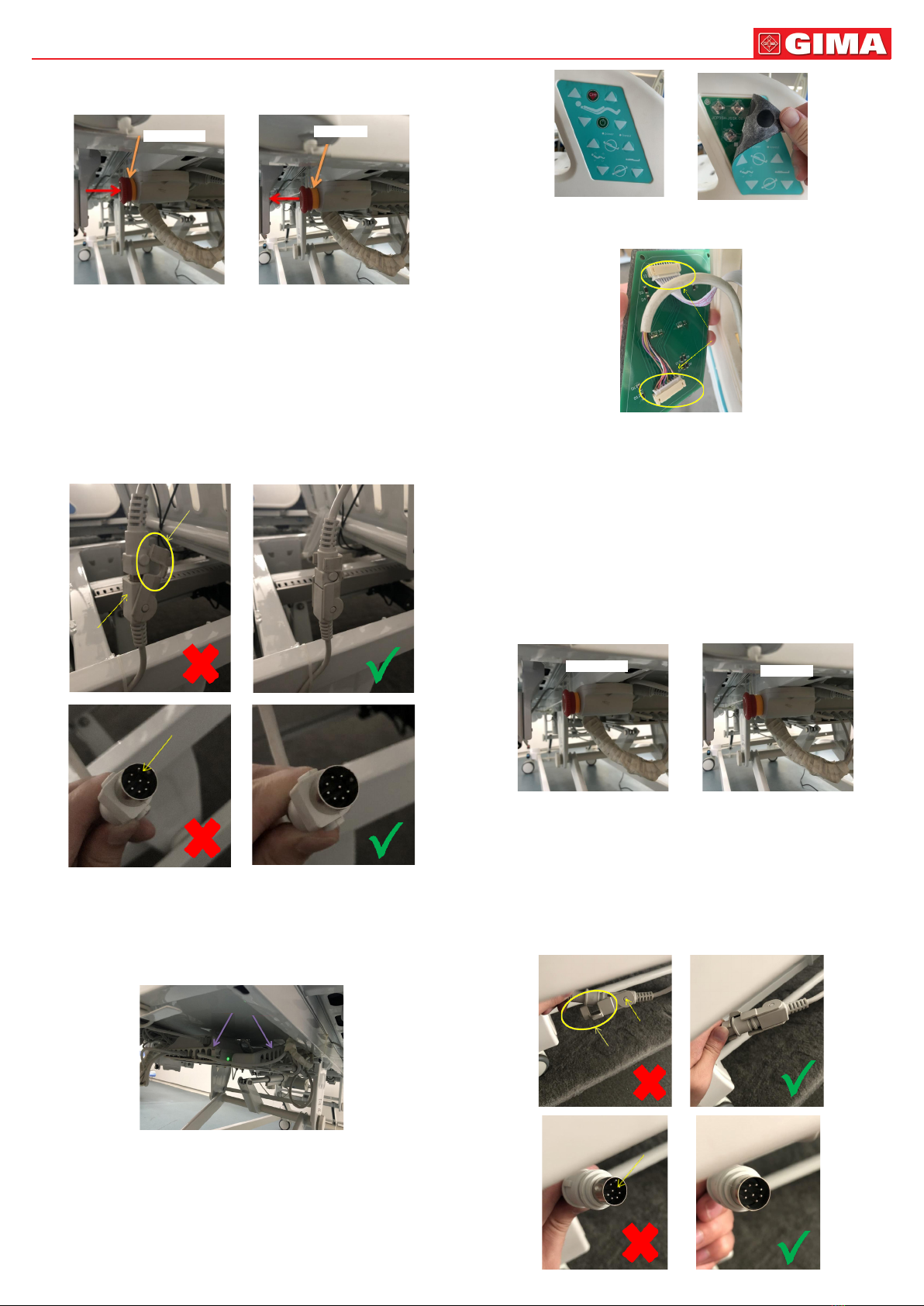
Pic. 2-2
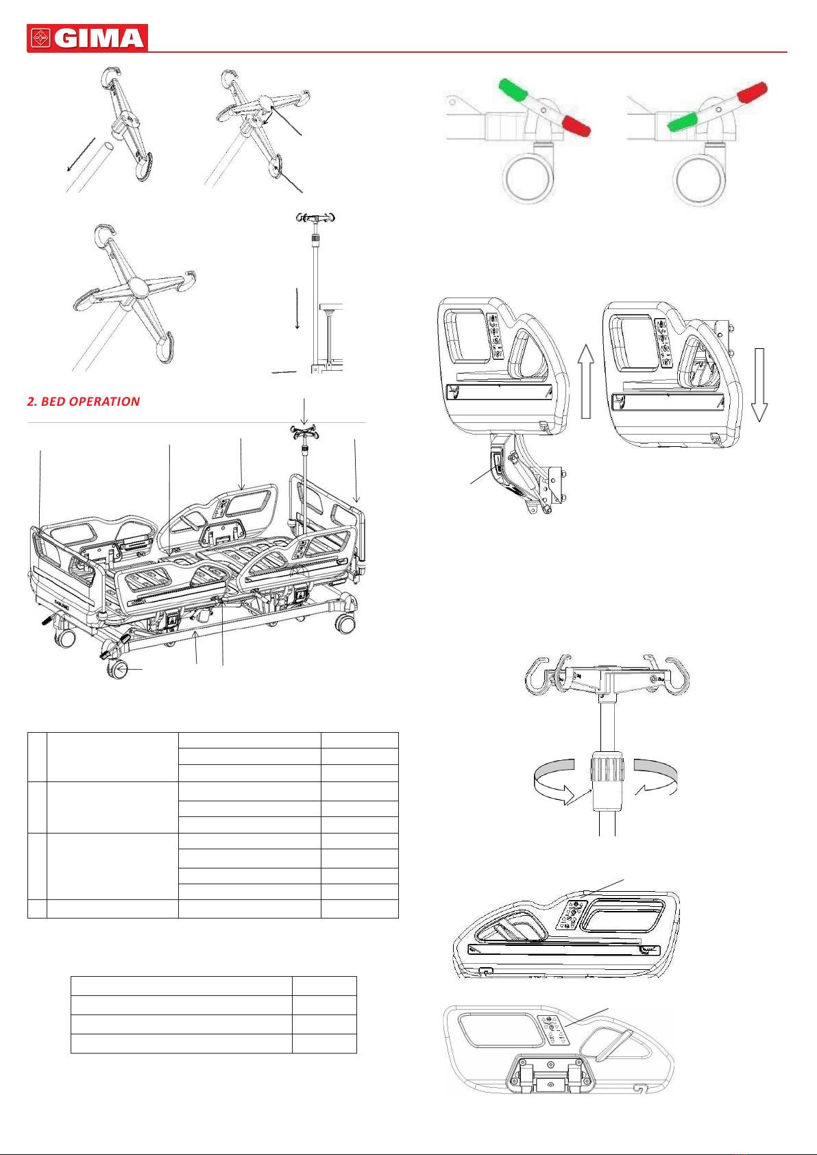
Step 3: Check if the controller plug is loose
A. Check the content: controller plug is loose;
B. Check method:
①Check if the controller clip on the bed frame under the back plate is loose or
dislodged, see pic.2-3;
②Check if the plug is loose;
La clip è allentata
Pic. 2-3
C. Problem determinaon: loose clips can easily lead to loose plugs, please fasten the
clips aer the plugs are rmly inserted;
D. Conclusion: aer the above three steps, check the side rail control panel, if it sll
unresponsive, means the control panel is damaged, and should be replaced.
5. BED MAINTENANCE
1. In order to use the bed safely, it is necessary to conduct regular safety inspecons
on the bed, it’s recommended to conduct a comprehensive inspecon every six mon-
ths to ensure the connecon parts are not loose and the liing funcon of the bed
is operang normally.
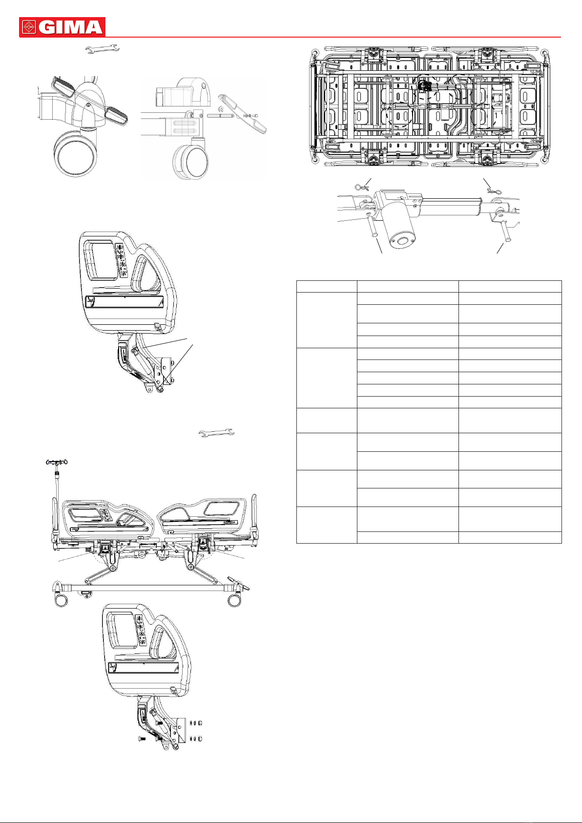
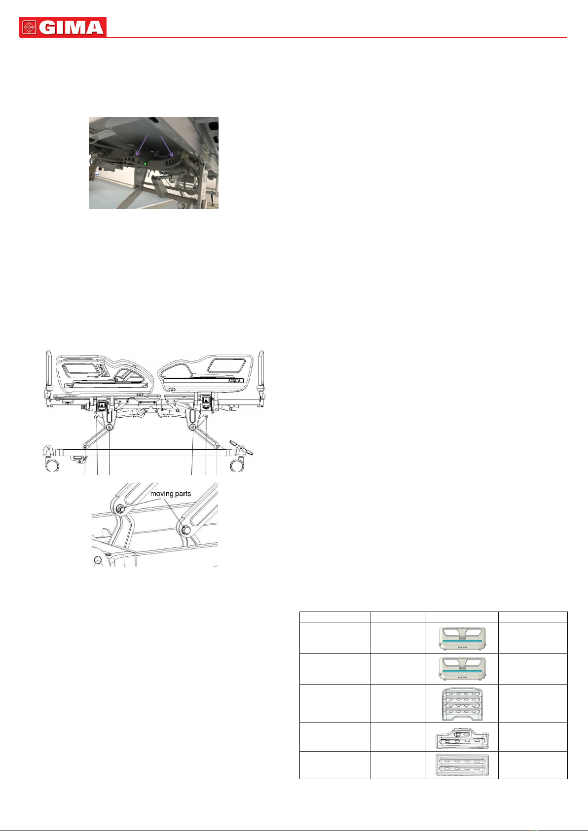
2. The connecon of the frequently moving parts of the bed needs to be lubricated
with an appropriate amount of oil during daily inspecon; is serious wear is found, it
should be replaced immediately to ensure safety. The moving part in gure below:
3. Avoid hing the bed and scratching the coang on the bed surface with sharp
objects.
4. Please prevent the bed and maress from absorbing water and moisture, which
may cause rust, abnormal noises and bacterial growth. If there was water spilled,
please wipe it o immediately.
5. When the bed ages and reaches its service life me, the metal part and the plasc
parts can be recycled.
6. BED CLEANING PRECAUTIONS
1. When cleaning, please wring the cloth soaked in neutral detergent diluted with
water, wipe it dry, then wring the cloth soaked in clean water, wipe o the residual
detergent ingredients, and nally wipe with a dry cloth.
2. Do not use volale items (thinners, propellants, gasoline, etc)
that may cause chemical reacons and damage the bed.
3. When cleaning with a disinfectant, be sure to use it aer dilung it at the specied
concentraon. Depending on the composion of the disinfectant, it may corrode me-
tal parts, resin parts, etc, causing discoloraon, deformaon and other undesirable
consequences. Therefore, the recommended content of the disinfectant is as
follows:
0.05~0.2% ammonium chloride
0.05~0.2% chlorinated phenyl
0.05% dichlorobenzene biguanide ethane
0.05~0.2% sodium hypochlorite
Do not use a smoking sterilizer or autoclave, and do not use methyl phenol to clean
the head foot board, bed feet, etc, which may cause corrosion, discoloraon, dete-
rioraon.
Note: 1. Unplug power cable before cleaning and maintenance
1. During the cleaning, DO NOT splash water to prevent short circuit and electric
shock.
2. When cleaning the bed or changing bedding, pay aenon to the corners, edges
and screw parts of the frame to prevent scratches.
7. MATTRESS MAINTENANCE
1. Avoid scratching the fabric with sharp-angled appliances or knives when using it,
cover it with sheets or cleaning pads, and clean it frequently to keep it clean and dry.
2. Regularly clean the maress cover with a vacuum cleaner, it can be washed direct-
ly with water or detergent.
3. Air the maress oen to keep your sleep fresh and comfortable, but be careful not
to expose the maress to the sun for too long.
4. If the fabric is accidentally stained, please refer to the corresponding recommen-
ded cleaning method in the instrucons. Do not use corrosive chemicals to clean
the fabric.
5. If you accidentally get chewing gum or other glue-like objects on the fabric, do
not wipe it forcibly. You can use am ice pack to allow it to harden and then peel it
o gently.
6. If the thread is found to be loose due to wear and tear, it cannot be broken by
hand, and it should be cut short with scissors.
8. CASTERS INSPECTION AND MAINTENANCE
1. Check the casters regularly, avoid hing heavy objects or overloading, which will
cause damage to the casters.
2. The casters should be applied with lubricang grease regularly, the frequency of
appliance should be determined according to the specic actual use situaon. Under
normal condions, the grease should be applied every six month.
3. Aer cleaning the caster equipment, pay aenon to adding lubricang grease.
The selecon of lubricang grease should be based on the actual use environment,
special high low temperature environment, etc.
4. It’s forbidden to push the bed with force when the casters are braked, which will
cause damage to the braking system.
5. The wear of the re tread of the caster can be detected by visual inspecon. Some
accumulaons such as thread and spun yarn may wrap around the caster. Remove
the bolts and nuts of thecaster, clean up the debris, and check whether the bearing
of the caster is damaged. If the parts are not damaged, the caster can be reassem-
bled and used.
6. Decision whether to replace enre caster is according to the wear condion. Aer
the caster is replaced or reinstalled, make sure that the axle bolt and nut are con-
nected reliably, and use lock washers or lock nuts as much as possible.
7. For casters equipped with brakes, it is necessary to regularly check whether the
brakes work normally, and check the brakes every day or before each use. For a ho-
spital bed equipped with mulple brake casters, you can lock only one brake caster
at a me and try to push the bed to check whether the braking performance of each
caster is good. If the caster brake fails to funcon due to wear or damage to the ca-
ster, replace the caster immediately and retest the brake system.
8. If the mechanism of the brake system is damaged, and the brake needs to be re-
paired or replaced, please contact our aer- sales or an authorized dealer. Every me
the brakes arereplaced, the brake performance of the casters needs to be retested.
9. SIDE RAILS MAINTENANCE
1. Please check whether the side rails are installed correctly to prevent the lying
paent from shiing and rolling o.
2. Please always check the screws of the side rail and the side rail ngs, to prevent
loosening and falling o.
3. Please use the red part of the side rail handle correctly, do not use brute force to
pull hard, which will cause damage to the side rail.
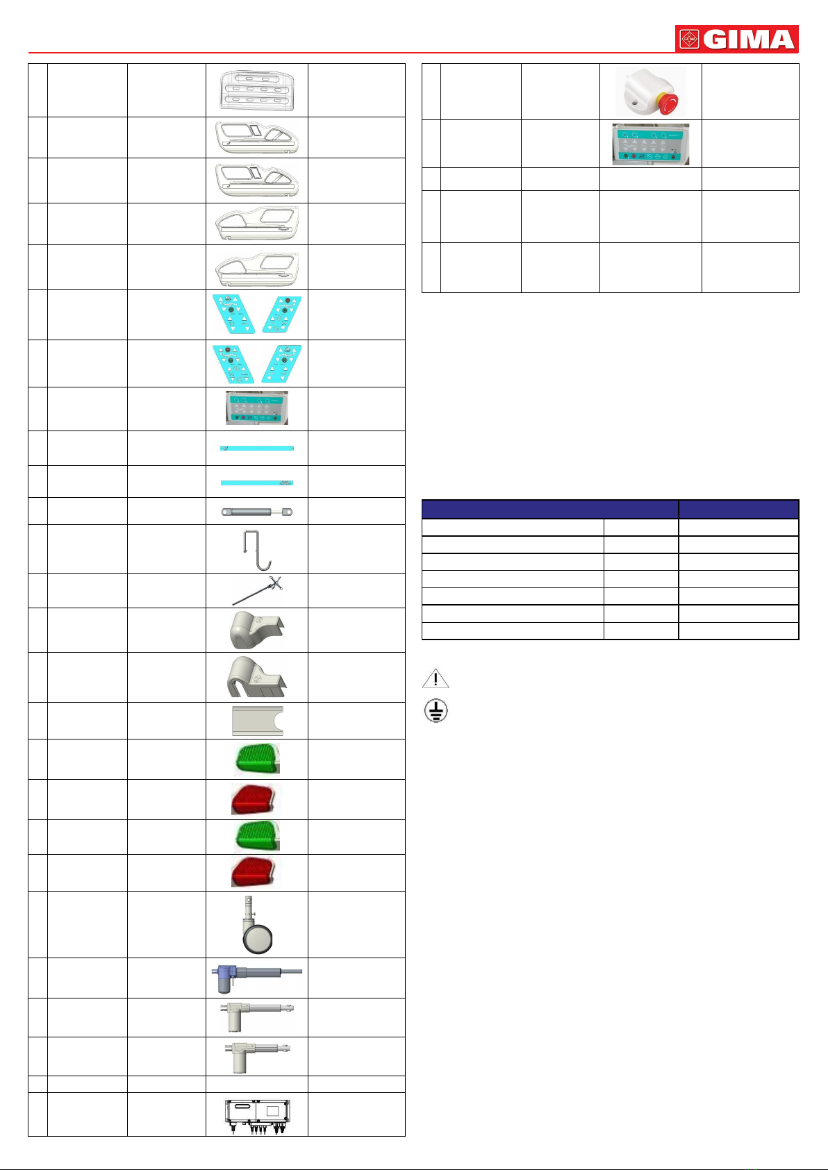
10. LIST OF WEARING AND SPARE PARTS
№Name Material code Picture Specication
1 V21 head board GPSL101TS648 990*460
2 V21 foot board GPSL101TS648 990*460
3V21 bed board 1 GPSL101TS610 733*903/PP/white
4 V21 bed board 2 GPSL101TS611 333*903/PP/white
5 V21 bed board 3 GPSL101TS613 373*903/PP/white