Gocycle G2 Gear Servo Technical manual

SERVICE DOCUMENT:G2 SERVO
VERSION 1.0
Service Document for the G2 Gear Servo

Gocycle Service Document: G2 Servo 1.0
October 2014 © Karbon Kinetics Limited. All Rights Reserved. i
CONTENTS
Overview........................................................................................................................1
Parts List........................................................................................................................1
Tool List.........................................................................................................................1
Best Practice Guidelines...................................................................................................2
Electrical System Best Practice Guidelines.........................................................................3
1.Right-Hand Crank Arm Removal .................................................................................4
2.Cleandrive®Cover Removal........................................................................................6
3.Chain Removal ..........................................................................................................8
4.Servo Removal ........................................................................................................10
5.Servo Installation.....................................................................................................18
6.Main PCB Refit.........................................................................................................24
7.Chain Installation.....................................................................................................26
8.Cleandrive®Inspection.............................................................................................27
9.Cleandrive®Cover Installation..................................................................................28
10.Crank Arm Installation .............................................................................................30

Gocycle Service Document: G2 Servo 1.0
October 2014 © Karbon Kinetics Limited. All Rights Reserved. 1
OVERVIEW
This service document details the service of the G2 Servo. If you have any questions, or
require any further assistance, please contact techsupport@gocycle.com.
PARTS LIST
The following parts are referenced within this document.
Note: When ordering replacement
parts from KKL, please quote the product code and quantity required.
Part Code Part Description Quantity
11 M5 x 24 Magform 12
2061 Crank Arm Right-Hand 1
2175 M4 x 24 dowel Pin SS A4 8
2225 Spring WS Carbon Steel 2
2283 20mm Crank Arm Bolts 1
KKL-2081-2632-02 Servo 1
KKL-2082-2275-00 Servo Horn 1
TOOL LIST
The following tools are required to successfully service the G2 Servo.
Part Code Tool Description
Allen Key, 2.5mm
T10 bit
T15 bit
T25 Extension Piece
Philips screwdriver
Knife
Pliers
Crank-puller (square taper type)
Chain splitter
Torque wrench (8mm Hex Bit)
Heat gun

Gocycle Service Document: G2 Servo 1.0
October 2014 © Karbon Kinetics Limited. All Rights Reserved. 2
BEST PRACTICE GUIDELINES
Before conducting any service or maintenance on the Gocycle ensure the following points
are adhered to:
1. The battery must be in ‘Sleep Mode’ (switched off).
2. Ensure the Gocycle is appropriately secured to prevent injury and damage.
3. If the Gocycle has been ridden continuously for more than 5 minutes, allow a minimum of 30
minutes before performing any maintenance or service activity on the electrical system.
Examples include removing, installing connecting or disconnecting the battery.
4. If maintenance is being performed within 30 minutes of usage, components such as the battery,
motor and gearbox may be hot. Treat these components with care and allow time to cool to a
safe handling temperature before conducting any maintenance.
5. Read and understand the following service document fully.
6. Only use the tools specified to complete assembly instructions and ensure torque requirements
are met and checked.
7. Follow all instruction steps accurately and in the correct order, taking note of any cautions
and/or warnings.
8. If in doubt, or you require further explanation on a procedure, please contact your authorised
Gocycle Service Centre for assistance or our Gocycle Technical Support Executives.

Gocycle Service Document: G2 Servo 1.0
October 2014 © Karbon Kinetics Limited. All Rights Reserved. 3
ELECTRICAL SYSTEM BEST PRACTICE GUIDELINES
1. It is not recommended to disconnect, connect, remove or install the battery in environments
above 40°C.
2. If you discover damage to any of the electrical system components other than light cosmetic,
such as exposed or corroded electrical connections or damaged wiring contact your authorised
Gocycle Service centre immediately and do not attempt to operate the Gocycle.
3. Do not short circuit the battery terminals.
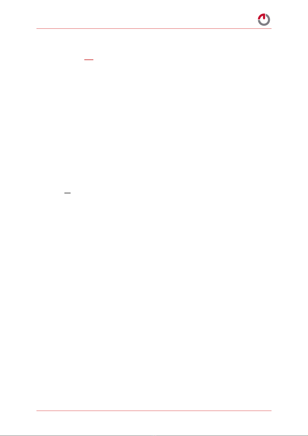
4. Power terminals must only be connected or
disconnected when the battery is in ‘Sleep Mode’
(switched off).
5. Use extreme care when handling the battery to
prevent any physical damage. Immediately contact
your authorised Gocycle Service centre if there is
physical damage.
6. Do not puncture or subject the battery to strong
impacts.
7. Do not attempt to disassemble or modify the battery.
8. Do not expose the battery to excess water or moisture.
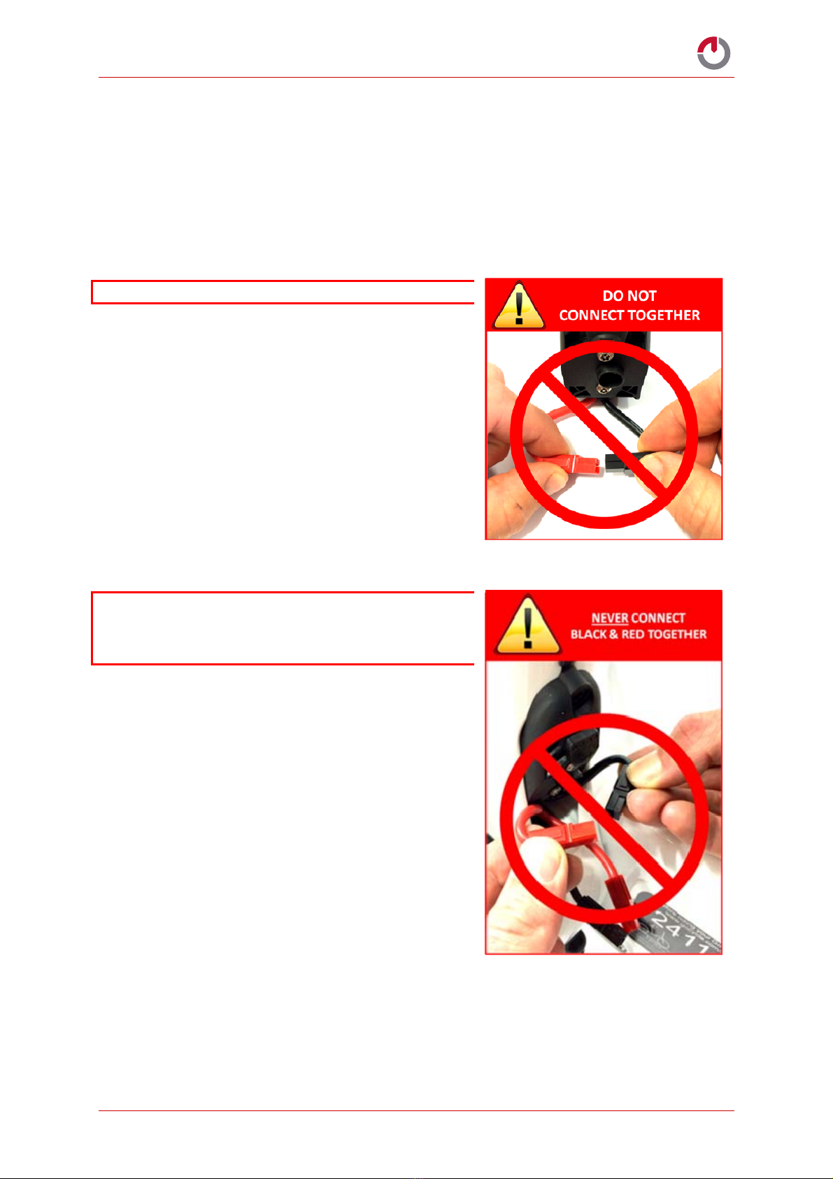
9. Ensure battery terminals are connected securely and
correctly; positive to positive (red-to-red), negative
to negative (black-to-black) before switching on your
Gocycle.
10. The battery has been designed specifically for use
with the generation-two (G2) Gocycle. Do not use
the battery with any other product.
11. The battery is intended to remain within the Gocycle
frame at all times and should be removed only by a
Gocycle-approved service centre or with the
assistance and approval of a Gocycle Technical
Support Executive.
12. Do not expose the battery to fire.
13. Only use the specified Gocycle G2 charger.
14. Do not leave the battery unattended whilst charging.
15. Only use, charge or store the battery in an
environment with ambient temperatures between 0°C and 40°C (32°F and 104°F) and a
humidity of 45% to 85% RH.
16. If you wish to remove the Gocycle Light Kit, the light harness on Gocycles FN <240000 must
also be removed.

Gocycle Service Document: G2 Servo 1.0
October 2014 © Karbon Kinetics Limited. All Rights Reserved. 4
1. RIGHT-HAND CRANK ARM REMOVAL
1.1. Invert the G2 and
locate in a work stand.
Remove both
PitStopWheels®.
1.2. Use a wrench with
an 8mm Hex bit to undo
the Right-Hand Crank
Arm Bolt (2283).

Gocycle Service Document: G2 Servo 1.0
October 2014 © Karbon Kinetics Limited. All Rights Reserved. 5
1.3. Use a square taper
crank puller to remove the
Right-Hand Crank Arm
(2061).
1.4. Take care when
removing the crank arm
and ensure to keep all 8
dowel pins (2175)
located as well as all 4
Carbon Steel Wave
Springs (2225).

Gocycle Service Document: G2 Servo 1.0
October 2014 © Karbon Kinetics Limited. All Rights Reserved. 6
2. CLEANDRIVE®COVER REMOVAL
2.1. Using a T25 Torx Bit,
unscrew the eleven
Magform Bolts (11) as
shown.
2.2. Rotate the Cleandrive®
upwards, as shown
2.3. Unscrew and remove
the remaining Magform Bolt
(11).
CHECK! There are a total
of 12 Magform Bolts to
unscrew before the
Cleandrive®cover can be
removed.

Gocycle Service Document: G2 Servo 1.0
October 2014 © Karbon Kinetics Limited. All Rights Reserved. 7
2.4. The Cleandrive®Cover
can now be removed ready
for internal inspection.

Gocycle Service Document: G2 Servo 1.0
October 2014 © Karbon Kinetics Limited. All Rights Reserved. 8
3. CHAIN REMOVAL
3.1. Use your thumb to apply
upward pressure on the Chain
Tensioner as shown.
3.2. Release the Chain
from the Chain Tensioner
and use the LockShock®Pin
to secure the Chain
Tensioner as demonstrated.
Note: You do not need to
completely remove the
chain. Derailing it from
the Chain Tensioner and
Chainring will be
sufficient for access to
the servo.

Gocycle Service Document: G2 Servo 1.0
October 2014 © Karbon Kinetics Limited. All Rights Reserved. 9
3.3. Allow the Chain to
hang free and remove the
Chainring from the Bottom
Bracket Spindle as shown.

Gocycle Service Document: G2 Servo 1.0
October 2014 © Karbon Kinetics Limited. All Rights Reserved. 10
4. SERVO REMOVAL
Note: Before commencing ensure the Gocycle battery is in ‘
Sleep Mode’
or disconnected and
removed
4.1. Once the Chainring
has been removed, the
Main Junction Board (JB)
will be v as shown.
4.2. Remove the
Junction Board by undoing
the retaining bolts.
Depending on Gocycle
Frame Number there may
be 3 or 4 securing bolts.
Use either a 2.5mm Allen
key or a T10 to undo the
securing bolts.
Note: Please note the
location of the securing
bolts on your model of
Gocycle for
reinstallation later on.

Gocycle Service Document: G2 Servo 1.0
October 2014 © Karbon Kinetics Limited. All Rights Reserved. 11
4.3. Remove the Main
Junction Board PCB taking
care not to touch the
components on the board,
as shown.
4.4. Hold the edge of
the Main Junction Board
PCB as shown, and remove
the 2 pin white connector.
This is the Rear Sensor.
4.5. Remove the 3 pin
connector as shown. This is
the Servo Cable.

Gocycle Service Document: G2 Servo 1.0
October 2014 © Karbon Kinetics Limited. All Rights Reserved. 12
4.6. Allow the chain to
rest as shown so that both
balance springs are free
and accessible.
4.7. Remove the Cable
Guide Upper by unscrewing
the two retaining bolts
using a Torx T15
Note: Depending on
Gocycle Frame Number
these may also be
Philips-head
screwdriver.

Gocycle Service Document: G2 Servo 1.0
October 2014 © Karbon Kinetics Limited. All Rights Reserved. 13
4.8. With the Cable
Guide Upper removed.
4.9. Pull the wires out
of the Cable Guide Lower
to reveal the heat-shrink-
wrapped section. These
wires are the Servo
Controller Cable (with the
flat black connector) and
the Rear Sensor Cable
(with the white connector).
4.10. Use a sharp blade
to very carefully cut off the
shrink-wrap, taking care
not to damage the wires
underneath.

Gocycle Service Document: G2 Servo 1.0
October 2014 © Karbon Kinetics Limited. All Rights Reserved. 14
4.11. When the shrink
wrap has been removed,
there may be excess wiring
coiled up underneath.
4.12. Unhook the E Shift
Balance Spring from its
mount on the Cleandrive.
4.13. Remove the E-Shift
Balance Spring from the
servo by unhooking from
the E Shift Spring Balance
Link, then remove the E-
Shift Spring Balance Link
from the servo.

Gocycle Service Document: G2 Servo 1.0
October 2014 © Karbon Kinetics Limited. All Rights Reserved. 15
4.14. With the E-Shift
Balance Spring removed,
the retaining bolt can also
be removed.
4.15. Use a 2.5mm Allen
key and take care to keep
the E-Shift Spring Spacer
with the bolt.
4.16. Remove the E-Shift
Spring.

Gocycle Service Document: G2 Servo 1.0
October 2014 © Karbon Kinetics Limited. All Rights Reserved. 16
4.17. Unhook the Servo
end first. Using pliers,
rotate the E-Shift Spring
towards you so that the
hooked end becomes free
of the Servo Horn, then
pull away from the Servo.
4.18. The E-Shift Spring
can be left hooked at the
other end.
4.19. Remove the three
M3 x 25 Caphead Servo
retaining bolts using a
2.5mm Allen Key. Make
sure to keep the washers
for reinstallation.

Gocycle Service Document: G2 Servo 1.0
October 2014 © Karbon Kinetics Limited. All Rights Reserved. 17
4.20. Remove the Cable
Guide Lower along with the
Servo from the Cleandrive
by pulling it away.
4.21. Remove the Servo
from the Cable Guide
Lower. This is done by
pulling the Servo out of the
Cable Guide Lower and
threading the cable out.
4.22. Completely remove
the Servo as shown.

Gocycle Service Document: G2 Servo 1.0
October 2014 © Karbon Kinetics Limited. All Rights Reserved. 18
5. SERVO INSTALLATION
5.1. To fit the new
Servo, first loop the Servo
Controller Cable through the
large lower hole in the Cable
Guide Lower, then back up
through the smaller upper
hole. Whilst pulling the wire
through, fit the servo back
into its mounting hole.
5.2. Front view of the
Servo correctly mounted into
the Cable Guide Lower.
NOTE: The Servo housing
should be flush with the
Cable Guide Lower.
5.3. Rear view of the
Servo correctly mounted into
the Cable Guide Lower. Take
care to ensure the Servo
Controller Cable clears both
of the bolt holes.
Table of contents
Other Gocycle Bicycle manuals

Gocycle
Gocycle G2 KICKSTAND Technical manual

Gocycle
Gocycle GS User manual

Gocycle
Gocycle G2 KICKSTAND User manual

Gocycle
Gocycle G2 KICKSTAND User manual

Gocycle
Gocycle G1 User manual

Gocycle
Gocycle G2R User manual

Gocycle
Gocycle 301 User manual

Gocycle
Gocycle G3 User manual

Gocycle
Gocycle G2 KICKSTAND User manual

Gocycle
Gocycle G1 Operation and maintenance manual