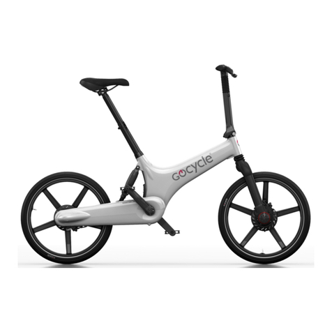
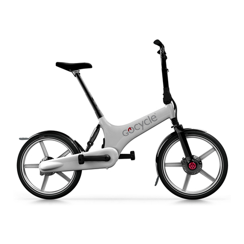
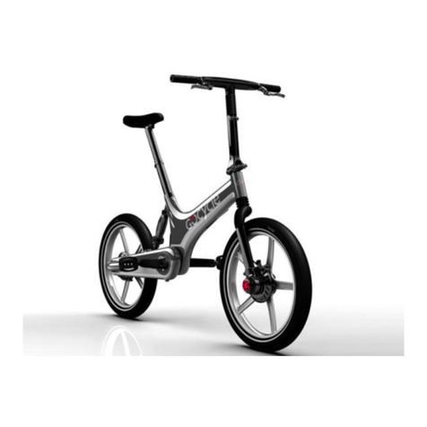
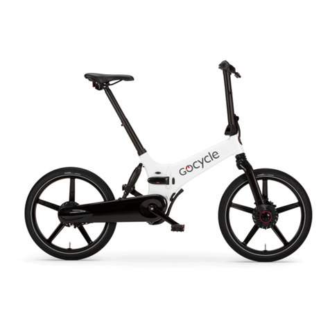
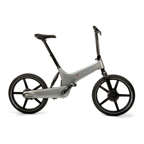
Gocycle G2 KICKSTAND Technical manual

SERVICE DOCUMENT:G2 FRONT HUB REWORK
VERSION 1.0
Servicing of the Gocycle G2 Front Hub

Gocycle Service Document: G2 Front Hub Rework 1.0
© Karbon Kinetics Limited. All Rights Reserved. i
CONTENTS
Overview.............................................................................................................1
Parts List .............................................................................................................1
Tool List .............................................................................................................1
1. Front Disk Cover Removal ...............................................................................2
2. Front Hub Removal .........................................................................................3
3. Front Hub Clutch Replacement.........................................................................6
4. Fork Upright Disassembly ................................................................................9
5. Front Hub Disassembly.................................................................................. 11
6. Front Hub Reassembly .................................................................................. 14
7. Fitting the Front Hub to the MotorFork ...........................................................18
Gocycle Service Document: G2 Front Hub Rework 1.0
© Karbon Kinetics Limited. All Rights Reserved. 1
OVERVIEW
This document details tear down and rebuild of the G2 Front Hub. If you have any
questions, or require any further assistance, please contact techsupport@gocycle.com.
PARTS LIST
To successfully complete the procedure you will require the following parts.
Note: You may
be able to re-use parts on your Gocycle and as such only need to order parts specific to your
repair.
Part Code
Part Description
Quantity
2100
Fork Brace
1
2135
Motor Torque Bung
6
2137
Front Disk Cover
1
2162
M5x25 BH SS A4 w/THDLCK
4
2163
M3x8 SH SS A4
6
2164
M4x6 BH SS A2
1
2256
M3x8 CSK SS A4 TX
4
TOOL LIST
To successfully complete this procedure you will require the following tools.
Special KKL
tools can be purchased by their tool number detailed below.
Part Code
Tool Description
1243
2.5mm Allen Key
1244
3mm Allen Key
1246
5mm Allen Key
2 x Small Flat Screwdriver
1355
Split Collect Extractor 8-11mm Spread
1356
Split Collect Extractor 13-16.5mm Spread
1357
Split Collect Extractor 38-50mm Spread
1358
Adaptor
1359
Slide Hammer
1361
MotorFork Separator Tool
1362
Motor Holder
1369
Hub Bearing Jig
1370
G2 Front Shaft Tool

Gocycle Service Document: G2 Front Hub Rework 1.0
© Karbon Kinetics Limited. All Rights Reserved. 2
1. FRONT DISK COVER REMOVAL
Note: Before commencing ensure the Gocycle is in
Sleep
mode
1.1. For ease of
assembly, invert the
Gocycle and locate
on a stand as
demonstrated.
Note: Ensure the
battery pack is in
sleep mode. Consult
your Owner’s Manual
for information.
1.2. Use a 2.5mm
Allen key and
unscrew the 6 bolts
(2163) that secure
the Front Disk Cover
(2137).
1.3. When all 6 bolts
have been removed
the Cover can be
separated from the
MotorFork.

Gocycle Service Document: G2 Front Hub Rework 1.0
© Karbon Kinetics Limited. All Rights Reserved. 3
2. FRONT HUB REMOVAL
2.1. Use a 5mm Allen
key to unscrew and
remove the two
calliper securing
bolts.
2.2. Use a 3mm Allen
key to undo the 4
bolts (2162) that
secure the Fork Brace
(2100).
2.3. Once all 4 bolts
have been removed
the Fork Brace can
be released from the
MotorFork.

Gocycle Service Document: G2 Front Hub Rework 1.0
© Karbon Kinetics Limited. All Rights Reserved. 4
2.4. Now the
MotorFork Separator
Tool (3177) must be
located in the
MotorGearbox fins as
demonstrated. The
top half of the tool
should align against
the Front Upright.
Note: Before
installing the tool
ensure the lower
component is
unscrewed to its
maximum extent.
Note: This
demonstrates
incorrect alignment
of the tool. It should
not locate against the
Disk.
2.5. Turn the thumb
screw to separate the
Front Hub from the
MotorFork. Remove
the Front Hub and
support the
MotorGearbox.

Gocycle Service Document: G2 Front Hub Rework 1.0
© Karbon Kinetics Limited. All Rights Reserved. 5
2.6. Support the
MotorGearbox and
Locate the Motor
Holder (3178). This
fits onto the
MotorFork as shown.
2.7. Slide the Motor
Holder up the Fork
into the fins of the
Motor and use the
elastic band to
secure the tool to the
MotorFork. Wrap the
elastic band around
the MotorFork twice
to ensure the holder
will not move.
The Motor Holder
securing the
MotorGearbox in
position preventing
damage to the phase
wires.

Gocycle Service Document: G2 Front Hub Rework 1.0
© Karbon Kinetics Limited. All Rights Reserved. 6
3. FRONT HUB CLUTCH REPLACEMENT
3.1. Slide the Front
hub assembly into
the Hub Bearing Jig
as demonstrated.
Ensure it is fully
located within the jig.
3.2. If the Clutch
gear cog is still
located within the
clutch then affix the
8-11mm split collect
extractor to the slide
hammer. Note the
adaptor is required to
attach the extractor
to slide hammer. If
the gear cog has
remained on the
MotorGearbox output
shaft then proceed to
step 3.6.
3.3. Install the slide
hammer and
extractor into the
front hub assembly
as demonstrated.
Hold the split collect
and tighten the
adjusting nut. This
will protrude into the
extractor and flare
the sides.

Gocycle Service Document: G2 Front Hub Rework 1.0
© Karbon Kinetics Limited. All Rights Reserved. 7
3.4. Hold the slide
hammer as
demonstrated and
using a quick strong
action slide the
weight up to the
stop. This action will
exert a force on the
lower edge of the
gear cog and extract
it.
3.5. The gear cog is
removed as
demonstrated.
3.6. Now install the
13-16.5mm split
collect extractor to
the end of the slide
hammer with
adaptor.

Gocycle Service Document: G2 Front Hub Rework 1.0
© Karbon Kinetics Limited. All Rights Reserved. 8
3.7. Install the slide
hammer and
extractor so it sits
within the inner race
of the clutch. Hold
the extractor still and
tighten the top nut as
demonstrated. This
protrudes into the
extractor flaring the
sides so that they
secure beneath the
inner race edge.
3.8. Hold the slide
hammer as
demonstrated and
using a quick strong
action slide the
weight up to the
stop. This action will
exert a force on the
lower edge of the
clutch and extract it.
3.9. Clutch extracted
from Front Hub.

Gocycle Service Document: G2 Front Hub Rework 1.0
© Karbon Kinetics Limited. All Rights Reserved. 9
4. FORK UPRIGHT DISASSEMBLY
4.1. Place the Fork
blade jig into the
Fork upright as
demonstrated.
4.2. Attach the Fork
brace and install the
4 securing bolts using
a 3mm Allen key.
4.3. Clamp the Fork
Blade Jig into a vice
and install the G2
Front Shaft Tool.
Note the dowels align
with the cut-outs in
the front axle.

Gocycle Service Document: G2 Front Hub Rework 1.0
© Karbon Kinetics Limited. All Rights Reserved. 10
4.4. Press the tool
into the axle as
demonstrated.
4.5. Install a breaker
bar as shown and
turn clockwise in
order to undo the
hub assembly from
the Fork upright.
4.6. The Fork Upright
assembly is removed
from the Fork
upright.

Gocycle Service Document: G2 Front Hub Rework 1.0
© Karbon Kinetics Limited. All Rights Reserved. 11
5. FRONT HUB DISASSEMBLY
5.1. Place the front
hub assembly into
the jig and use a flat
screwdriver to
remove the circlip
that retains the front
shaft and bearings.
Use one flat
screwdriver to
prevent the circlip
from rotating and the
other to prise the
sharp edge free.
5.2. Circlip removed
from the Front hub
assembly.
5.3. Now install the
38-50mm Split collet
extractor.

Gocycle Service Document: G2 Front Hub Rework 1.0
© Karbon Kinetics Limited. All Rights Reserved. 12
5.4. Grip the lower
portion of the
extractor and tighten
the top nut as
demonstrated.
Ensure the extractor
is located beneath
the outer bearing and
lower edge of the
axle.
5.5. Now install the
slide hammer into
the extractor as
demonstrated.
5.6. Hold the slide
hammer as
demonstrated and
using a quick strong
action slide the
weight up to the
stop. This action will
exert a force on the
lower edge of the
outer bearing and
axle.

Gocycle Service Document: G2 Front Hub Rework 1.0
© Karbon Kinetics Limited. All Rights Reserved. 13
5.7. The whole axle
assembly should
come free as shown.
5.8. Undo the split
collet extractor nut
and the shaft and
two bearings should
be free as shown.

Gocycle Service Document: G2 Front Hub Rework 1.0
© Karbon Kinetics Limited. All Rights Reserved. 14
6. FRONT HUB REASSEMBLY
6.1. Install the clutch
Gear cog into the
clutch bearing as
shown. Ensure the
keyway is installed
correctly. This push
fit can be completed
by hand or through
the use of a vice.
6.2. Place the clutch
bearing into the jig
as shown.
Note: The bearing
must be orientated in
this direction with the
‘balls’ face down. The
outer keyway must
also locate within the
jig.
6.3. Place the Front
hub onto the jig as
demonstrated.

Gocycle Service Document: G2 Front Hub Rework 1.0
© Karbon Kinetics Limited. All Rights Reserved. 15
6.4. Rotate the hub
from side to side until
the hub locates on
the outer keyway of
the clutch.
6.5. Press down onto
the jig until the
clutch is fully located
within the front hub.
Clutch fully installed.

Gocycle Service Document: G2 Front Hub Rework 1.0
© Karbon Kinetics Limited. All Rights Reserved. 16
6.6. Place the front
shaft and bearing
assembly into the
front hub.
6.7. Place the front
shaft bearing press
tool onto the Hub
assembly as shown.
6.8. Place this into a
vice with soft jaws
installed and close
until the shaft and
bearings are fully
seated within the
hub.

Gocycle Service Document: G2 Front Hub Rework 1.0
© Karbon Kinetics Limited. All Rights Reserved. 17
6.9. Place the
assembled Front hub
into the jig and
reinstall the circlip.
Note the orientation
of the open end.
6.10. With the fork
upright and jig
secured in the vice
offer the front hub
and shaft tool as
shown.
6.11. Install a
breaker bar as shown
and turn anti-
clockwise in order
to tighten the hub
assembly to the Fork
upright. 243 Loctite
should be used on
the shaft thread
when reinstalling.
Take care not to
contaminate the
bearing.

Gocycle Service Document: G2 Front Hub Rework 1.0
© Karbon Kinetics Limited. All Rights Reserved. 18
7. FITTING THE FRONT HUB TO THE MOTORFORK
7.1. Line up the 6
Spring pins with the
Motor Torque Bungs.
The Clutch will need
to be manually
aligned with the
output shaft of the
MotorGearbox. To do
this, slowly turn the
Hub until it aligns
with the Output shaft
and then tightly press
the Hub and
MotorGearbox
together.
7.2. Ensure the
MotorGearbox and
Front hub assembly
are fully inserted and
the edge of the fork
is on the shoulder of
the Hub assembly as
shown here.
7.3. Reinstall the
Calliper and securing
bolts as
demonstrated. Do
not fully tighten.
Other manuals for G2 KICKSTAND
3
Table of contents
Other Gocycle Bicycle manuals

Gocycle
Gocycle G2 KICKSTAND User manual

Gocycle
Gocycle GS User manual

Gocycle
Gocycle G2R User manual

Gocycle
Gocycle G2 KICKSTAND User manual

Gocycle
Gocycle G2R User manual

Gocycle
Gocycle G3 User manual

Gocycle
Gocycle G2 Gear Servo Technical manual

Gocycle
Gocycle G1 User manual

Gocycle
Gocycle G2 KICKSTAND User manual

Gocycle
Gocycle G1 Operation and maintenance manual