golmar K-ACCESS PAC-90 User manual

K-ACCESS
Placa de control
de accesos
PAC-90
T51
La comunicación por sistema
Golmar se reserva el derecho a cualquier modificación sin previo aviso.
Golmar reserves the right to make any modifications without prior notice.
1
4
7
C
2
5
8
3
6
9
0
rev.0101

Descripción.
Description. Notas:
Notes:
d
165
b
c
g
f
k
k
j
o
o
g
l
l
h
Placa de aluminio.
d
b
cc
e
a
Conector cable plano.
Placa teclado.
128
f
i
n
n
c
h
cm
m
e
a
i
i
j
Junta estanqueidad.
1 2 3 4
-+12 ~1 ~2 CV2 CV1 TP A2 A1
Indicador de código correcto.
Correct code indicator.
Indicador de código incorrecto y bloqueo de acceso.
Incorrect code and access blocked indicator.
Marcos laterales.
Side frames.
Aluminium panel.
Cabezales embellecedores.
Decorative head mounts.
Tecla de borrado.
Delete key.
Teclado.
Keyboard.
Interruptores de TAMPER y grabación de códigos.
TAMPER and code recording microswitches.
Flat cable connector.
Regleta de conexión.
Connector terminals.
Bisagra abatimiento.
Lowering hinge.
Keyboard printed circuit.
Waterproof seal.
Orificios sujeción placa.
Panel fixing holes.
Orificio confirmación de pulsación.
Call confirmation hole.
1
4
7
C
2
5
8
3
6
9
0

Funcionamiento.
Cómo cerrar y abrir la placa.
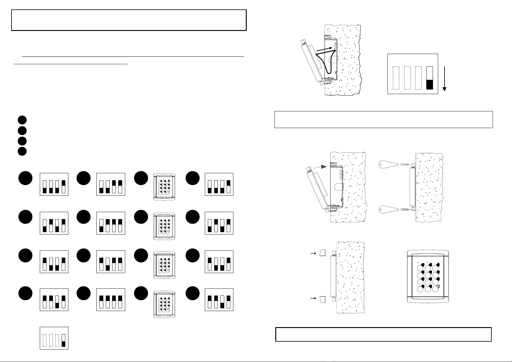
Para cerrar la placa activando el circuito de TAMPER:
- Conectar el extremo del hilo del TAMPER al borne de la caja de empotrar como se
ha explicado anteriormente. Procurar que no quede demasiado largo, ya que si alguien abre
la placa, se debe desconectar el otro extremo para activar el relé (al que se puede conectar
una alarma). Tampoco hay que dejarlo demasiado corto, ya que debemos tener espacio
para activarlo mediante el dip4.
- Una vez conectado el hilo, bajar el dip4 del microinterruptor para activarlo.
- Cerrar la placa normalmente.
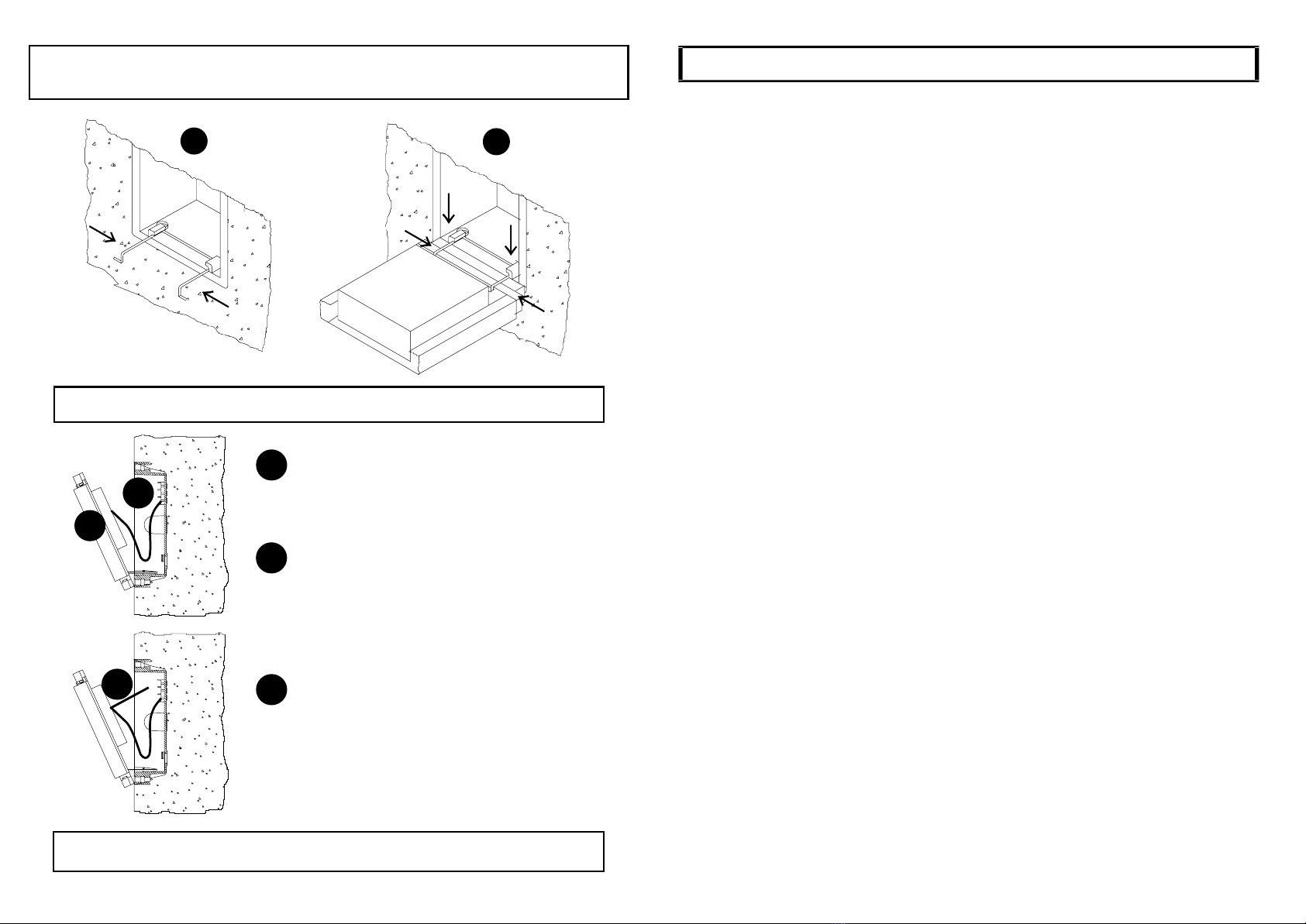
Para abrir la placa si está activado el TAMPER:
- Desatornillar y abrir la placa con cuidado para no desconectar el hilo de TAMPER.
- Subir el dip4 del microinterruptor para desactivarlo.
-Ahora ya se puede desconectar el hilo y abrir la placa normalmente.
How to close and open the panel.
To close the panel and activate the TAMPER circuit:
- Connect the end of the TAMPER wire to the terminal in the flush-fitting box as
previously explained. Make sure the wire is not too long, because if someone opens the
panel the other end must disconnect to activate the relay (which can be connected to an
alarm). On the other hand the wire must not to be so short, because there must be space to
activate dip4.
- Once the wire is connected, lower dip4 to activate.
- Close the panel.
To open the panel if the TAMPER circuit is activated:
- Unscrew and open the panel taking care not to disconnect the TAMPER wire.
- Raise microswitch dip4 to disable.
- Now you can disconnect the wire and open the panel normally.
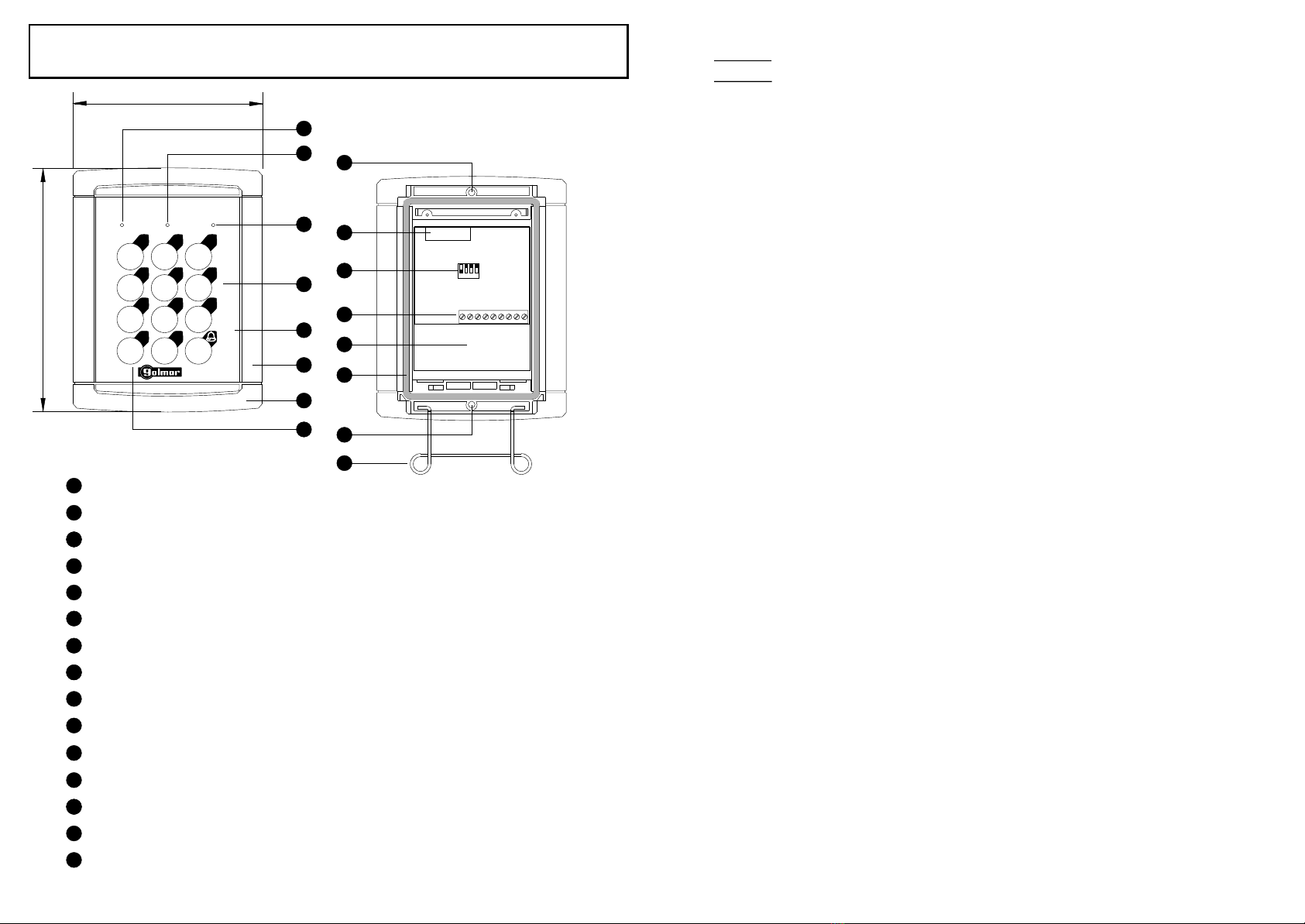
El funcionamiento del control de accesos consiste en el accionamiento del
sistema de abrepuertas cuando el código de cuatro cifras introducido coincide
con alguno de los códigos pregrabados.
- El total de códigos diferentes que se pueden grabar son tres de apertura
normal y un cuarto de apertura con código de pánico.
- Los códigos grabados de fábrica son: 1111, 2222, 3333 y 4444.
- Para introducir el código pulsar las teclas en la secuencia correcta,
simultáneamente se oirá un pitido que confirmará la pulsación. Si el código es
correcto, se encenderá el led verde y se accionará el sistema de abrepuertas
durante cuatro segundos.
Si el tiempo entre dos pulsaciones excede los cuatro segundos, el sistema
vuelve al estado de condiciones iniciales, habrá que introducirlo de nuevo desde
el principio.
Si se quiere corregir el código, pulsar la tecla C y volver a introducirlo.
Si el código introducido es el de pánico, en primer lugar se encenderá el led
verde y se abrirá la puerta al igual que el resto y en segundo lugar se accionará
un relé durante un minuto, al cual se puede conectar, por ejemplo, un sistema de
activación de alarma (características del relé: 120 Vca-0'5 A, 24 Vcc-1 A). Si el
código de pánico coincide con alguno de los otros tres, no accionará el relé.
- Si el código introducido es incorrecto, se enciende el led rojo durante cuatro
segundos y se bloquea la placa durante este tiempo. Transcurrido el mismo, el
sistema queda a la espera de la introducción de un nuevo código.
Si se introducen cinco códigos erróneos consecutivos, se encenderá el led
rojo y se bloqueará la placa durante un minuto. Transcurrido este tiempo el
sistema volverá al estado de condiciones iniciales.
- En caso de fallo en la alimentación, los códigos no se borran.
- Existe la posibilidad de accionar un relé (bornes A1, A2, características del
relé: 120 Vca-0'5 A, 24 Vcc-1 A) en caso de que la placa se abra, es lo que se
denomina TAMPER. Consiste en conectar un hilo entre el terminal TP de la
regleta de conexión y un punto a masa (-), asegurándose de que al estirar de la
placa este hilo se desconecte.Además hay que poner hacia abajo el dip 4.

Conectar el faston del hilo de Tamper al otro conector. Bajar el dip 4 para activarlo.
Connect the TAMPER faston to the other connector. Lower dip4 to activate.
1 2 3 4
Incorporar y fijar la placa. Ensamblar los cabezales embellecedores.
Attach and fix the panel. Assemble the decorative head frames.
1
4
7
C
2
5
8
3
6
9
0
Grabación de códigos.
Se puede grabar un total de cuatro códigos de acceso. Cada código tiene
cuatro cifras.
El proceso de grabación se debe realizar estrictamente en el orden que
se muestra (del código 1 al código 4).
Después de introducir el código 4 el equipo se bloqueará durante tres
minutos. Compruebe que la grabación de códigos se ha realizado con éxito
transcurrido este intervalo de tiempo. Si finalizado el proceso de grabación se
desconecta el equipo de la alimentación y se vuelve a conectar, el bloqueo
desaparecerá, pudiendo iniciar la comprobación de códigos.
Grabación del primer código:
Grabación del segundo código:
Grabación del tercer código:
Grabación del cuarto código (pánico):
Activación del TAMPER: bajar el dip 4.
1
1
1
1
1
1
1
1
1
1
1
1
1
2
2
2
2
2
2
2
2
2
2
2
2
2
3
3
3
3
3
3
3
3
3
3
3
3
3
4
4
4
4
4
4
4
4
4
4
4
4
4
1
1
1
1
1
2
2
2
2
2
3
3
3
3
3
4
4
4
4
4
Seleccionar la posición donde se va a grabar (dips 1 y 2).
Subir el dip 3. Activa la grabación.
Introducir el código de cuatro cifras mediante el teclado.
Bajar el dip 3. Desactivación del modo de grabación.
1
4
7
C
2
5
8
3
6
9
0
1
4
7
C
2
5
8
3
6
9
0
1
4
7
C
2
5
8
3
6
9
0
1
4
7
C
2
5
8
3
6
9
0

Ensamblaje de la placa en la caja de empotrar a través del muelle bisagra.
Assembly of the panel in the flush-fitted box using the springed hinge.
Operation
Conexión del TAMPER. Opcional.
TAMPER connection. Optional.
2
2
3
3
1
1
Montaje.
Assembly.
2
1
Atornillar un hilo y un conector tipo "faston"
macho a uno de los bornes de la caja de
empotrar.
Connect a wire and a male "faston" connector
to one of the screw holes of the flush fitting box.
Atornillar el otro extremo del hilo al borne
de masa del circuito del teclado.
Connect the other end of the wire to the earth
terminal (-) in the keyboard circuit.
Atornillar otro hilo, más corto, al borne TP
de la regleta del teclado. El otro extremo
debe terminar en "faston" hembra.
Connect another shorter wire to the TP
terminal in the keyboard circuit. Connect a
female "faston" connector to the other end.
The system operates the door-release when the 4 digit number keyed
in is the same as one recorded.
- The total number of differents codes that can be recorded are three for
normal opening and one to open and activate the panic code.
- The factory recorded codes are: 1111, 2222, 3333 and 4444.
- To key in the code press the keys in the correct sequence,
simultaneously a bleep will confirm that each key is pressed. If the code is
correct, the green led lights and door release mechanism is activated for
about four seconds.
If the time between two keys being pressed exceeds 4 seconds, the
system reverts to the initial state and you must begin again.
if a mistake is made keying in the code, press the delete key C, and start
again.
If the panic code is keyed in, first the green led will light and the door will
open as usual, and secondly a relay is activated for 1 minute, which can be
connected to what you want (characteristics: 120 Vac-0'5 A, 24Vdc-1 A). If
the panic code coincides with one of the other three, the relay will not be
activated.
- If the code keyed in is incorrect, the red led lights for four seconds and
the door panel shuts off for this time. After this, the system returns to the
initial rest state.
If five consecutive incorrect codes are keyed in, the red led lights and
the panel shuts off for 1 minute. After this the system returns to the initial
rest state.
- If there is a power failure, the codes are not deleted.
- It is possible to activate a relay (A1, A2 terminals, characteristics: 120
Vac-0'5 A, 24Vdc-1 A) if the panel is opened, this is called TAMPER. It
consists of connecting a wire between terminal TP and an earth point (-),
ensuring that if the panel is pulled out this wire disconnects. Dip4 must also
be placed in the down position.

Diagramas de instalación.
Installation diagrams.
Placa de control de accesos / Access control panel.
Placa de control de accesos + PE-90 / Access control panel + PE-90.
Placa de control de accesos + PE-91, PE4-91 ó PV-90
Access control panel + PE-91, PE4-91 or PV-90
CV
CV2
CV1
+12
-
2TPA1 A2 121
PAC-90
PAC-90
PAC-90
TF-103
220V
12V
CV
PE-90
PE-91, PE4-91 ó PV-90
M.SONIDO
M.SONIDO
P CV
+
-
1
P CV
+
-
1
PLUZ-90
PLUZ-91
M
M
CV
L1
-
-
2
L2
VO
1
1
O
ICO
L1
+V
+
+12
+12
TP
TP
CV1
CV1
CV2
CV2
-
-
2
2
A2
A2
1
1
A1
A1
1
4
7
C
2
5
8
3
6
9
0
1
4
7
C
2
5
8
3
6
9
0
1
4
7
C
2
5
8
3
6
9
0
Recording codes.
You can record four access codes. Each code has four digits.
The recording procedure must be strictly done in the same order as
shown (from 1st code to 4th code). When the 4th code has been recorded, the
system will remain blocked during three minutes. Check that the recorded codes
operate correctly once the three minutes has been passed. If the system is
disconnected from the power supply and connected it again, the codes could be
checked inmediately.
Recording first code:
Recording second code:
Recording third code:
Recording fourth code (panic code):
TAMPER activation: push down the dip4.
1
1
1
1
1
1
1
1
1
1
1
1
1
2
2
2
2
2
2
2
2
2
2
2
2
2
3
3
3
3
3
3
3
3
3
3
3
3
3
4
4
4
4
4
4
4
4
4
4
4
4
4
1
1
1
1
1
2
2
2
2
2
3
3
3
3
3
4
4
4
4
4
Select memory position (dips 1 and 2).
Push up dip 3. Recording option enabled.
Introduce code with the keyboard.
Push down dip 3. Recording option disable.
1
4
7
C
2
5
8
3
6
9
0
1
4
7
C
2
5
8
3
6
9
0
1
4
7
C
2
5
8
3
6
9
0
1
4
7
C
2
5
8
3
6
9
0
Table of contents
Languages: