manuals.online logo
Brands
  1. Home
  2. •
  3. Brands
  4. •
  5. Norton
  6. •
  7. Door Opening System
  8. •
  9. Norton PR7570 Series User manual

Norton PR7570 Series User manual

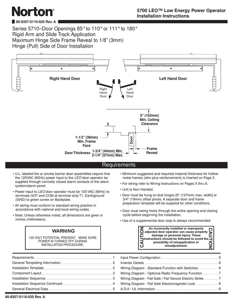
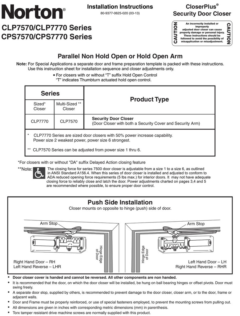
PR7570/PR7770 SeriesSecurity Door Closer80-9377-0621-020 (03-13)Note: For Special Applications a separate door and frame preparation template is packed with these instructions. Use this instruction sheet for installation sequence and closer adjustments only.For Hold Open function, consult factory or authorized representativeParallel Non Hold Open or Hold Open ArmProduct TypeSeries* PR7770 Series are sized door closers wi h 50% power increase capability. Power size 2 weakest power, power size 6 strongest.** PR7570 Series can be adjusted from power size 1 thru 6.tPush Side InstallationCloser mounts on opposite to hinge (push) side of door.Right Hand Door – RHLeft Hand Reverse – LHR
Hinge Edgeof Door
Left Hand Door – LHRight Hand Reverse – RHR• Door closer cover is handed and cannot be reversed. All other components are non handed.• It is recommended that the door, on which the door closer will be installed, be hung on ball bearing hinges or offset pivots. Door must swing freely.• A separate door stop, supplied by others, is recommended to prevent damage to the door closer, closer arm, or to the door, frame or adjacent walls.• Door and Frame must be properly reinforced, or use of special fasteners employed, to prevent the mounting screws from pulling out.• All dimensions are given in inches with corresponding metric dimensions (mm) in parenthesis.• Torx tamper resistant drive machine screws are normally supplied with this product.Sized*CloserMulti-Sized **CloserPR7770PR7570Security Door Closer(Door Closer with both a Security Cover and Security Arm)
Hinge Edgeof Door
Installation InstructionsAn incorrectly installed or improperly adjusted door closer can cause property damage or personal injury. These instructions should be followed to avoid the possibility of misapplication or misadjustment.
CAUTION
CAUTION
**Note: *For closers with or without "DA" suffix Delayed Action closing feature
Template5 Holes for Soffit Plate7/16(11)1/2(13)2-1/16(52)3/8(10)2-3/4(70)2(51)1-3/8(35)BLeft Hand Door ShownRight Hand Installation is OppositeCLHinge or Pivot6-3/4(172)4(102)4-3/4(121)5/16(8)Prepare These Holes Only WhenNo. 7788 Drop Plate is UsedC2-9/16(65)12-3/4(324)1-1/16(27)4 Holes for CloserWide Stop Frame2-3/4(70)Min.Soffit PlateNarrow Stop Frame2-3/4(70)Min.1-1/8(29)5/8(16)Soffit Plate2019S BlockDo Not Scale DrawingLeft Hand Door ShownDimensions are in inches (mm).Maximum Door Swing 180°, conditions permitting.Min.2-3/8(61)ATo 100°101° to 120°121° to 180°Opening8-5/87-7/86-3/4219200171inchesmmDim. ADim. B9-1/88-3/87-1/4232213184inchesmmDim. C8-3/87-5/86-1/2213194165inchesmmMaximum Hinge width 5" (127) for doors swingingbeyond 150 degrees.Power Adjustment ChartDOORINTEXTPARALLEL ARMINSTALLATIONMAXIMUM DOOR SIZE32”(0.81 m)36”(0.9 m)42”(1.1 m)48”(1.2 m)*16 -360° TURNS MAXIMUM AVAILABLE*PR7570PR77700402362558588811INTEXT1280-9377-0621-020 (03-13)Preparation for Fasteners
Standard
Door orFrameFastenersDrill-Sizes1/4" - 20Machine ScrewMetalDrill: #7 (0.201" dia.)Tap: 1/4" - 20
Optional
Sex Nuts and Bolts(SNB)HollowMetal9/32" (7 mm); through3/8" (9.5 mm) on door or transom-faceopposite to closerAluminumor Wood3/8" (9.5 mm) through• Set closer power for door size using chart below.Install closer per instructionswith the proper pre-load applied to the arm then adjust spring power. The power adjustment will not work properly ifthe closer spring is notpre-loaded.To increase power, use 11/16"wrench to turn poweradjustment nut clockwise.To decrease power, turn nutcounter clockwise. DO NOT use a power drill or driver to turn adjustment nut. This will damagecloser and void warranty.Page 2"Spring PowerAdjustment Nut"+
-
TURNS FROM ZERO
Left Hand Door
Flat
Right Hand Door
Flat
Page 3• Mount closer on door. (A drop plate is available for use on doors having narrow top rails) Power Adjustment Nut should be away from hinge. Valves are DOWN for Left Hand Door. Valves are UP for Right Hand Door.• Use 1/8” hex wrench to close valves. Turn Clockwise. For STANDARD CLOSER, close valves ‘S/D’ and ‘L’. DELAYED ACTION CLOSER, close valves ‘S’ and ‘L’.Start (wrench) hereRotateInstall arm here• Place main arm on shaft, aligning mark on arm with pinion flat on pinion shaft; “Z” for Left Hand Door; “Y” for Right Hand Door. Secure with 1/4-20 x 1/2 (13) round head machine screw with hex head machine screw.80-9377-0621-020 (03-13)• Reopen valves closed in Step 2. Turn Counterclockwise• With door closed, align soffit plate with mounting holes in frame. Fasten soffit plate to frame with flat head screws provided.• Adjust closer per instructions on page 4 before installing cover
CAUTION!
DO NOT BACK VALVES OUT OFCLOSER OR A LEAK WILL RESULTInstall Cover:• Screw Standoffs into holes in closer. • screws provided.Fasten cover to closer with 4 #8-32x1/4 round head Installation Sequence•Use template on page 2 to locate holes on door and frame:4 on door for closer or drop plate.5 on underside of frame stop for soffit plate.•Prepare door and frame for fasteners using chart above.Main Arm Screw
Norton® is a registered trademark of Yale Security Inc., an ASSA ABLOY Group company. Copyright © 2002, 2013, Yale Security Inc., an ASSA ABLOY Group company. All rights reserved.Reproduction in whole or in part without the express written permission of Yale Security Inc. is prohibited.
3000 Highway 74 East • Monroe, NC 28112Tel: (877)- • Fax: (800)-338-0965www.nortondoorcontrols.com974-2255
ASSA ABLOY
Unit AdjustmentOpening Door ControlsFigure 4BackcheckFigure 5
1/8"HexKey
IncreaseDecreaseOpening Cycle
1/8"HexKey
Opening Door Control (Figure 4.)• Backcheck ("B") valve controls the hydraulic resistance to door opening. NEVER close this valve completely – it is not to provide a positive stop.• Backcheck position ("P") valve controls the door angle where backcheck cushioning starts. Valve normally closed.
a
c
B
k
c
h
e
c
k
g
n
i
n
e
p
O
Backcheck CushionBackcheck PositionOpen for backchecklater in door-openingcycle.Closing Speed ControlsClosing Speed ControlsFigure 2Figure 32B2A
1/8"HexKey
SlowFast"L" (Latch)"L" (Latch)"S/D” (Sweep)"S" (Sweep)"S/D" (Delayed Action)StandardClosing CycleDelayed ActionClosing CycleClosed
10°
70°
h
c
t
a
L
Closed
10°
h
c
t
a
L
R
a
e
p
e
n
w
g
e
S
D
e
l
a
y
R
a
n
g
e
p
e
e
w
S
Standard CloserDelayed ActionCloserAll ValvesDo not force valvescounter-clockwise outof closer body or a fluidleak will occur.Do not force valvescounter-clockwise outof closer body or a fluidleak will occur.Closing Power ControlFigure 1Install closer per instructionswith the proper pre-load applied to the arm then adjust spring power. The power adjustment will notwork properly if the closerspring is not pre-loaded.To increase power, use 11/16"wrench to turn poweradjustment nut clockwise.To decrease power, turn nutcounter clockwise. DO NOT use a power drill or driver to turn adjustment nut. This will damage closer and void warranty.For PR7570 OnlySet closer to desired size. For recommended sizes, refer to the Power Adjustment Chart on page 2.80-9377-0621-020 (03-13)Page 4"P"(Normally Closed)"B"(NEVER CloseCompletely)+
-

This manual suits for next models

1

Other Norton Door Opening System manuals

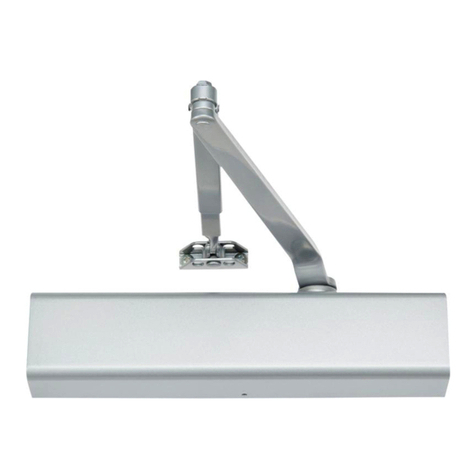
Norton Assa Abloy D6001DE-L Series User manual

Norton

Norton Assa Abloy D6001DE-L Series User manual

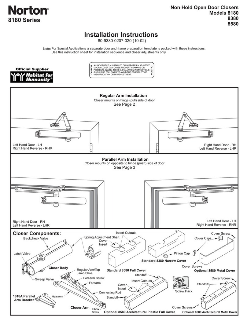
Norton 8380 User manual

Norton

Norton 8380 User manual

Norton Power Track Series User manual

Norton

Norton Power Track Series User manual

Norton Power Track Master Unit PTD Series User manual

Norton

Norton Power Track Master Unit PTD Series User manual

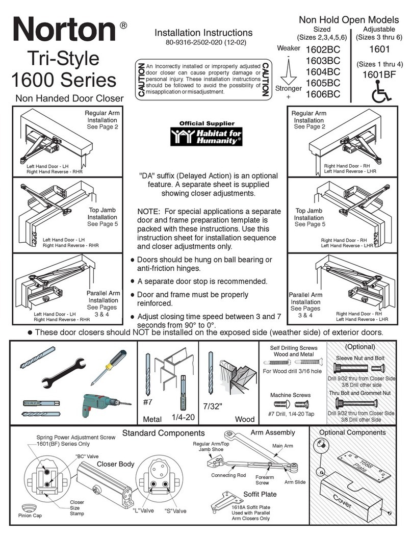
Norton Tri-Style 1600 Series User manual

Norton

Norton Tri-Style 1600 Series User manual

Norton 6900 PowerMatic User manual

Norton

Norton 6900 PowerMatic User manual

Norton LEO 5710 Series User manual

Norton

Norton LEO 5710 Series User manual

Norton tri-style 1603BC User manual

Norton

Norton tri-style 1603BC User manual

Norton CloserPlus CLP7570 Series User manual

Norton

Norton CloserPlus CLP7570 Series User manual

Norton 8000 Series User manual

Norton

Norton 8000 Series User manual

Norton 1600 Series User manual

Norton

Norton 1600 Series User manual

Popular Door Opening System manuals by other brands

Assa Abloy Corbin Russwin ED5400 (A) Series installation instructions

Assa Abloy

Assa Abloy Corbin Russwin ED5400 (A) Series installation instructions

Dormakaba 1856 HT SD installation instructions

Dormakaba

Dormakaba 1856 HT SD installation instructions

Bohle MasterTrack BT Teleskop 3 instruction manual

Bohle

Bohle MasterTrack BT Teleskop 3 instruction manual

BEA MS51 manual

BEA

BEA MS51 manual

Artweger TWISTLINE Assembly instructions

Artweger

Artweger TWISTLINE Assembly instructions

GEZE GC 308 R installation instructions

GEZE

GEZE GC 308 R installation instructions

D+H VCD 204-TMS+ Set Original instructions

D+H

D+H VCD 204-TMS+ Set Original instructions

Cal-Royal 8600 Operation & installation manual

Cal-Royal

Cal-Royal 8600 Operation & installation manual

Hafele Slido Series installation instructions

Hafele

Hafele Slido Series installation instructions

Proteco COMPACT Series Installation and use manual

Proteco

Proteco COMPACT Series Installation and use manual

Superlift SlimFit Installation instructions and user guide

Superlift

Superlift SlimFit Installation instructions and user guide

Dorma Manet Mounting instruction

Dorma

Dorma Manet Mounting instruction

Mobeye Call-Key MCK100 installation manual

Mobeye

Mobeye Call-Key MCK100 installation manual

Häfele Finetta T 70 VF manual

Häfele

Häfele Finetta T 70 VF manual

SECO-LARM SD-998C-D3Q installation manual

SECO-LARM

SECO-LARM SD-998C-D3Q installation manual

Allegion LCN 4311 HSA installation instructions

Allegion

Allegion LCN 4311 HSA installation instructions

RIB TAG Reader manual

RIB

RIB TAG Reader manual

CAME FA01467M4A quick start guide

CAME

CAME FA01467M4A quick start guide

manuals.online logo
manuals.online logoBrands
  • About & Mission
  • Contact us
  • Privacy Policy
  • Terms and Conditions

Copyright 2025 Manuals.Online. All Rights Reserved.