golmar TEKNA GTWIN User manual

Code 50123595 T GTWIN ENTEKNA REV.0119
TEKNA MONITORGTWIN
USER MANUAL

INTRODUCTION
First of all, we thank and congratulate you for purchasing this product manufactured by Golmar.
Our commitment to achieving the satisfaction of customers like you is manifested through our ISO-9001 certification
and the manufacture of products like the one you have just purchased.
Its advanced technology and strict quality control will ensure that customers and users enjoy the numerous features
that this device offers. To get the most out of them and ensure proper operation from day one, we recommend that you
read this instruction manual.
CONTENTS
2
SAFETY PRECAUTIONS
-Avoid overtightening the screws of the monitor connector.
-Always disconnect the power supply before installing or making modifications to the device.
-The fitting and handling of these devices must be carried out by authorised personnel.
-All of the wiring must run at least 40cm away from any other wiring.
-Install the monitor in a dry protected location free from the risk of dripping or splashing water.
-Do not place in humid, dusty or smoky locations, or near sources of heat.
-Before connecting the system to the mains, check the connections between the door panel, power supply, distributors
and monitors.
-Always follow the instructions contained in this manual.
Introduc ....................................................................................................................................................................2tion
Contents ...................................................................................................................................................................... ..2.
Safety precautions........................................................................................................................................... .2............. .
Characteristics...............................................................................................................................................................3
System operation......................................................................................................................................... .3................. .
Description of the monitor.................................................................................................................................................
Descrip ................................................................................................................................................................. 4tion ..
............................................................................................................................................................. .4.... .
Status LED
Indicator LED.............................................................................................................................................................. 4.
..................................................................................................................................4.
Communication with hearing aid
................................................................................................................................................. .5........Function buttons
.................................................................................................. ................... ................................... 6-7SW1 DIP switch
......................................................................................................... ............ ................................... ...8.SW2 DIP switch
.............................................................................................................................................................8EL-569 module
.............................................................................................................................. .............. .9.RCTK monitor connector
.............................................................................................................................................................10.Monitor fixing
Advanced programming (monitor functions)................. ............ .................................................................. ..... .1. . ... ....... 1
Programming the intercom function between different apartments.............................................................. ....... ...1. . 2-13.
Programming the intercom function in the same apartment.................................................... .......... .......... 1..... . ....... 4-15.
Cancellation of the monitor's intercom codes................................................................................................................15.
Optional connections................................................................................................................................................ .......
- .......................................................................... ..16.. ............... .
Button for receiving calls from the apartment front door
- .................................................. ....................................................... 16............ ..Additional call repeater (SAV-GTWIN)
- ................................ ........................................................ 1............ . 7.Additional call repeater with SAR-12/18 relay unit
- ......................................... ......................... 17. .....Monitors/telephones in parallel (input-output) in the same apartment
- ................................................................................................................................................ 1.8Cleaning the monitor
Wiring diagram................................................................................................ ........................................ .19....... .............
TEKNA GTWIN MONITOR

CHARACTERISTICS
-Monitor for Gtwin installation.
-3.5” TFT colour screen.
-Monitor with simple installation (unpolarised 2 wire BUS).
-Enables communication with hearing aids equipped with T-mode, making conversation possible (inductive loop).
-Function and programming access buttons (to customise monitor functions).
-Completely private conversation and image.
-Auto spy function.
-'Doctor mode' function (automatic door opening, see p. 11).
-Intercom between two devices in the same apartment (programmable).
.
-Intercom between two devices in different apartments (programmable).
-Input for calls from the apartment front door.
-Call volume control (maximum, minimum and no volume).
-Output to auxiliary call repeater.
-Call to guard unit.
-Different ringtones to identify call origin: Main door panel, slave door panel, guard unit, intercom and interior door of
the apartment.
-Control of brightness and colour.
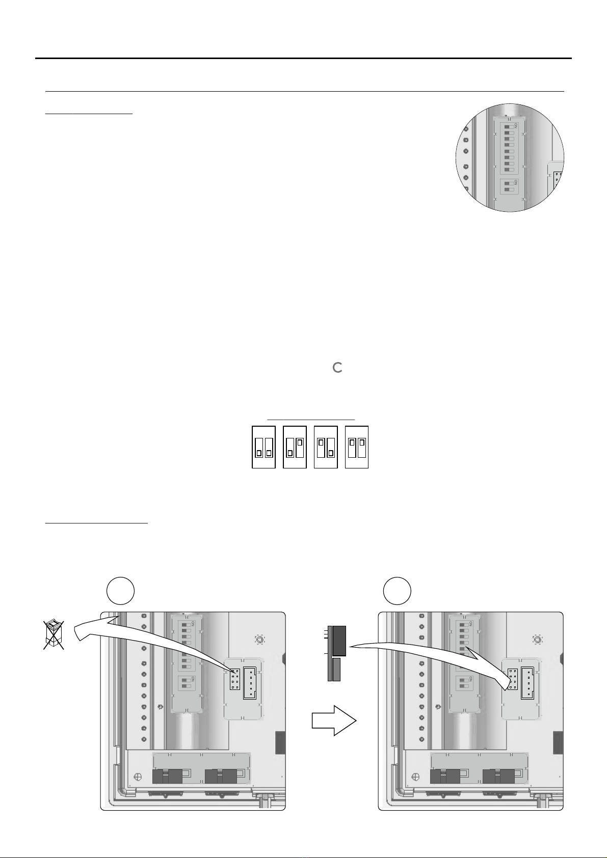
-SW1 DIP switches for setting the 'call code (user)' monitor address.
.
-SW2 DIP switches for setting the monitor as master/slave 1, slave 2 or slave 3.
-Button for activating the main lock release.
.
-Button for activating the slave lock release.
-Monitor status LED.
-Indicator LED.
SYSTEM OPERATION
3
-To make a call, the visitor presses the button for the apartment, a number of audible tones indicate that the call is being
made and LED on the door panel illuminates. At this moment, the apartment's monitor(s) receives the call. If the
visitor presses the button for another apartment by mistake, the call can be cancelled by pressing the button for the
correct apartment.
-In systems with several access doors, the other door panel(s) will automatically disconnect; if another visitor wishes to
call, LED on the door panel will blink for 3 seconds. If the vocal synthesis module is installed on the door panel, the
message 'communicating' will indicate that the channel is busy.
-General entrance door panels (main): If the call is being made from the general entrance door panel, the interior door
panel of the building being called and other possible general entrance door panels automatically disconnect; if another
visitor attempts to call from either a busy interior door panel, an audible tone will indicate that the channel is busy and
LED of the door panel will blink for 3 seconds, or from another general entrance door panel, an audible tone will
indicate that the channel is busy and LED of the general entrance door panel will blink for 3 seconds. The door
panels of the other interior buildings will remain free to be used.
-General entrance door panels (main): If the call is made from an interior door panel, the other interior door panels will
remain free to be used. It is only possible to make calls to interior buildings from the general entrance door panels
when their door panels are not in use; if an attempt is made to make a call to a busy interior door panel, an audible tone
will indicate that the channel is busy and LED of the general entrance door panel will blink for 3 seconds.
-The call lasts for 60 seconds, during which time an image appears on the master monitor of the apartment when the
call is received without the visitor knowing, and the indicator LED of the monitor(s) will illuminate (green). To view the
image on a slave monitor, press button and the image disappears from the monitor that was displaying it. If the call
is not answered within 60 seconds, the indicator status LED on the monitor(s) and LED on the door panel will turn off
and the channel will become free.
-To establish communication, pick up the monitor handset, the indicator LED of the monitor will remain illuminated
(green), LED of the door panel will now illuminate and LED of the door panel will turn off. Communication with
hearing aid: The handset enables communication with hearing aids equipped with T-mode, making conversation
possible (inductive loop).
-Guaranteed communication time is 90 seconds (configurable); after 90 seconds of guaranteed communication time,
the channel will become free.
-To end communication, hang up the handset, the indicator LED of the monitor and LED of the door panel will turn off
and the channel will become free.
-To open the main or secondary door, press the corresponding button / during the call or communication
processes: one press will activate the lock release for 1 second (configurable main door) and, with the opening of the
main door, LED will also illuminate for 1 second.
-Adescription of the function buttons can be found on p. 5.
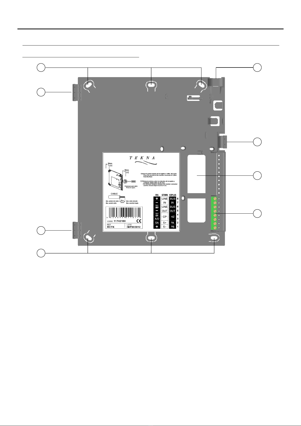
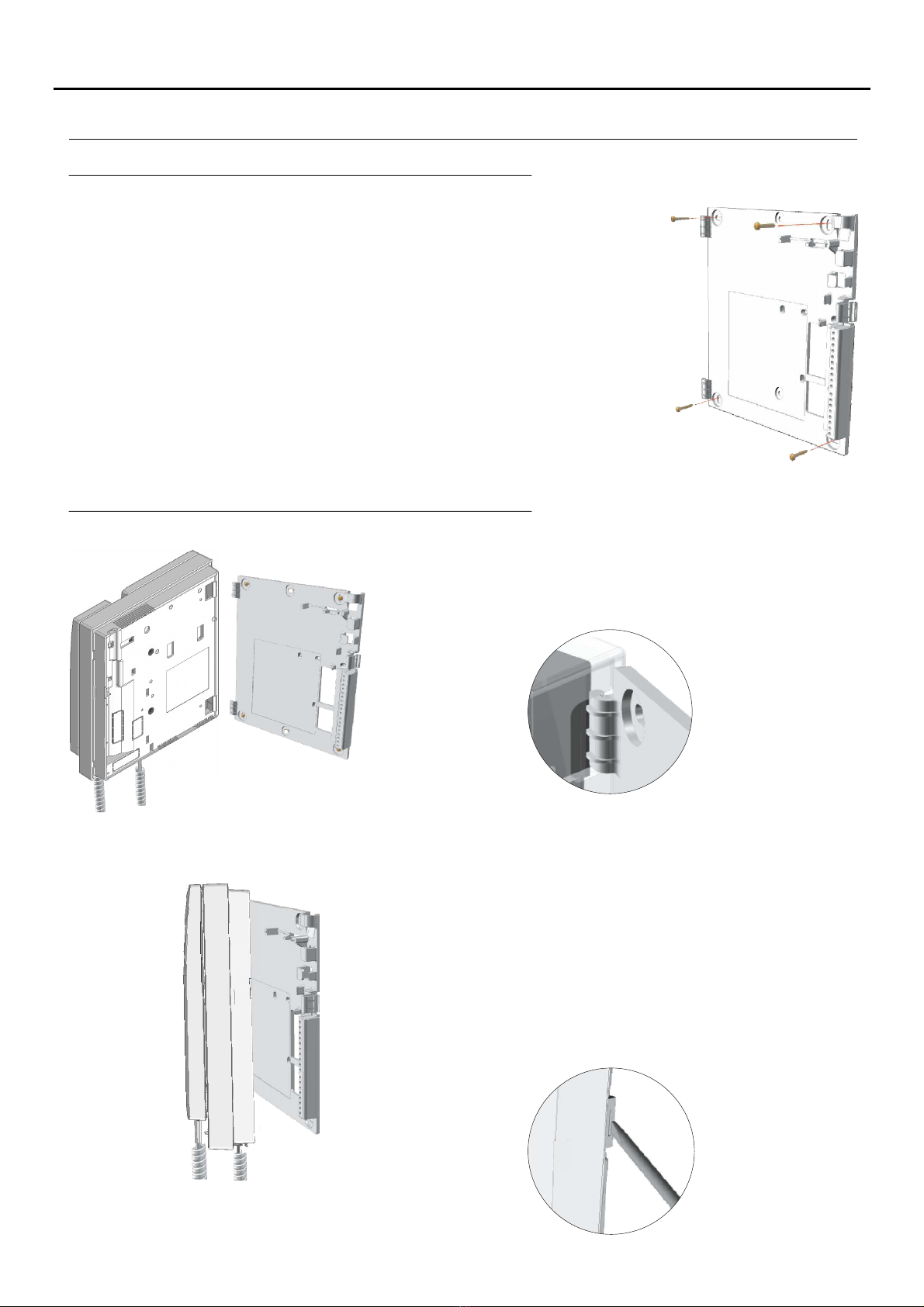
TEKNA GTWIN MONITOR

DESCRIPTION OF THE MONITOR
4
a.
b.
c.
d.
e.
f .
g.
h.
i .
j .
k.
l .
m.
n.
o.
Handset.
Colour screen.
Monitor status LED (three-coloured):
-No volume (call): LED blinking red rapidly.
-Doctor mode: LED blinking green.
-State of the open door on the main door panel:
LED illuminated red.
(See the TGTWIN SYSTEM MANUAL, p. 10).
-State of the open door on the slave door panel:
LED blinking red slowly.
(See the TGTWIN SYSTEM MANUAL, p. 10).
-Programming mode: LED blinking yellow.
Monitor indicator LED.
-Standby: LED off.
-In call, communication or auto spy: LED On green.
Function/programming buttons.
Telephone cord.
Connector fixings.
Identification label.
J4 end of line jumper or EL569 in-out unit connector.
DIP switches of the user code.
DIP switches of the internal code.
Connector connection points.
Cord connector.
Contrast control.
Brightness control.
ag
b
no
c
l
h
f
e
00000000000
.xx
MASTERINTER A1 SLAVE CODE
ESCALERA
STAIR
PISO
FLOOR
PUERTA
DOOR
ATENCIÓN
Alta tensión. No abrir la tapa.
Manipular sólo por personal
del servicio técnico.
WARNING
High voltage. Don't open cover.
Handle only by technical service.
SN
REF.
TEKNA PLUS SE
CODE
11742105
1 2 3 4 5 6 7 8
i
k
m
d
Description of the Tekna Gtwin monitor:
1 2
j
TEKNA GTWIN MONITOR
T
Communication with hearing aid:
The Tekna Gtwin monitor enables communication with hearing aids equipped
with T-mode, making conversation possible (inductive loop).
Note: Device compatible with all hearing aids equipped with T-mode
(ETS Standard 300381 and EN 60118).

5
DESCRIPTION OF THE MONITOR
Function buttons:
In standby and with the handset off the hook: it activates the intercom between 2 devices in the same
apartment or in different apartments (this feature must be pre-programmed, see p. 12-15).
During a call, communication or auto-spy process, it enables the slave lock release to be activated: one
press will activate the lock release for 1 second.
In standby and with the handset off the hook: it enables a call to be made to the guard unit.
In standby and with the handset off the hook: it activates the intercom between 2 devices in the same
apartment or in different apartments (this feature must be pre-programmed, see p. 12-15).
Note:Activation of the function disables the function.'intercom' 'call to guard unit'
In standby and with the handset on the hook: it enables programming mode to be entered or exited by
pressing and holding for 5 seconds, a number of short audible tones will indicate that the monitor is in
programming mode and the status LED will blink slowly (yellow) or a number of long audible tones will
indicate that the monitor has saved and left programming mode, and the status LED will turn off.
In standby and with the handset on the hook: it enables the image from the door panel configured as main to
be viewed (if the channel is busy, a number of short audible tones on the monitor will indicate so); if the
handset is then picked up, it enables audio and video communication with the door panel to be established.
During a call process: it enables the slave monitors (in the same apartment) to capture the image of the
door panel, with the image on the monitor that was displaying it disappearing.
In standby and with the handset off the hook: it activates the intercom between 2 devices in the same
apartment or in different apartments (this feature must be pre-programmed, see p. 12-15).
During call reception and communication processes, it enables the main lock release to be activated.
TEKNA GTWIN MONITOR
To restore the monitor's default parameters, after entering programming mode by pressing button for more than
5 seconds, simultaneously press buttons and for more than 3 seconds; confirmation of the command will
be indicated by 2 long audible tones and the monitor's exit from programming mode.
To facilitate repair, replacement or the addition of monitors to
the existing installation, fill in the label with the relevant
information.
MASTER: main monitor.
SLAVE: slave monitor.
INTER: monitor with intercom function.
A1: Not used.
CODE: call button code.
STAIRWAY: code of the channel (building).
Description of the identification label:
.xx
REF.
CODE
00000000000
MASTERINTER A1 SLAVE CODE
ESCALERA
STAIR
PISO
FLOOR
PUERTA
DOOR
ATENCIÓN
Alta tensión. No abrir la tapa.
Manipular sólo por personal
del servicio técnico.
WARNING
High voltage. Don't open cover.
Handle only by technical service.
SN

6
MONITOR SETTINGS
S 1W DIP switch:
The DIP switch is located on the left-hand side of the back of the monitor. It enablesSW1
the monitor to be configured by assigning it a user code address (apartment).
CODE: User code.
Set a number from 0 to 126, respecting the following rules:
In the column/riser, there should not be different apartments with the same user code.
In the case of monitors/telephones in parallel in the same apartment, these must have the same user code.
The user codes of the same column/riser must be consecutive.
To set the desired code, use the CODE DIP switches from 2 to 8 (2 = most significant bit and 8 = least significant bit);
DIP switch 1 must be OFF.
Factory setting
ON
US 4ER
7654321 8
ON
US 5ER
7654321 8
ON
US 0ER
7654321 8
ON
US 1ER
7654321 8
ON
US 2ER
7654321 8
ON
US 3ER
7654321 8
ON
US 6ER
7654321 8
ON
US 7ER
7654321 8
ON
US 8ER
7654321 8
ON
US 9ER
7654321 8
ON
US 10ER
7654321 8
ON
US 11ER
7654321 8
ON
US 12ER
7654321 8
ON
US 13ER
7654321 8
ON
US 14ER
7654321 8
ON
US 15ER
7654321 8
ON
US 16ER
7654321 8
ON
US 17ER
7654321 8
ON
US 18ER
7654321 8
ON
US 19ER
7654321 8
ON
US 20ER
7654321 8
ON
US 21ER
7654321 8
ON
US 22ER
7654321 8
ON
US 23ER
7654321 8
ON
US 24ER
7654321 8
ON
US 25ER
7654321 8
ON
US 26ER
7654321 8
ON
US 27ER
7654321 8
ON
US 28ER
7654321 8
ON
US 29ER
7654321 8
ON
US 30ER
7654321 8
ON
US 31ER
7654321 8
ON
US 32ER
7654321 8
ON
US 33ER
7654321 8
ON
US 34ER
7654321 8
ON
US 35ER
7654321 8
ON
US 48ER
7654321 8
ON
US 49ER
7654321 8
ON
US 36ER
7654321 8
ON
US 37ER
7654321 8
ON
US 38ER
7654321 8
ON
US 39ER
7654321 8
ON
US 40ER
7654321 8
ON
US 41ER
7654321 8
ON
US 42ER
7654321 8
ON
US 43ER
7654321 8
ON
US 44ER
7654321 8
ON
US 45ER
7654321 8
ON
US 46ER
7654321 8
ON
US 47ER
7654321 8
ON
US 50ER
7654321 8
ON
US 51ER
7654321 8
ON
US 52ER
7654321 8
ON
US 53ER
7654321 8
*
( )
*
( ) Continued overleaf
SW1
1 2 3 4 5 6 7 8 1 2
SW2
SW1
SW1 DIP SWITCH:
TEKNA GTWIN MONITOR

Continued from previous page.
7
MONITOR SETTINGS
ON
US 84ER
7654321 8
ON
US 85ER
7654321 8
ON
US 86ER
7654321 8
ON
US 87ER
7654321 8
ON
US 102ER
7654321 8
ON
US 103ER
7654321 8
ON
US 108ER
7654321 8
ON
US 109ER
7654321 8
ON
US 110ER
7654321 8
ON
US 111ER
7654321 8
ON
US 114ER
7654321 8
ON
US 115ER
7654321 8
ON
US 116ER
7654321 8
ON
US 117ER
7654321 8
ON
US 118ER
7654321 8
ON
US 119ER
7654321 8
ON
US 54ER
7654321 8
ON
US 56ER
7654321 8
ON
US 57ER
7654321 8
ON
US 58ER
7654321 8
ON
US 59ER
7654321 8
ON
US 60ER
7654321 8
ON
US 61ER
7654321 8
ON
US 62ER
7654321 8
ON
US 63ER
7654321 8
ON
US 55ER
7654321 8
ON
US 64ER
7654321 8
ON
US 65ER
7654321 8
ON
US 66ER
7654321 8
ON
US 67ER
7654321 8
ON
US 68ER
7654321 8
ON
US 69ER
7654321 8
ON
US 70ER
7654321 8
ON
US 71ER
7654321 8
ON
US 72ER
7654321 8
ON
US 73ER
7654321 8
ON
US 74ER
7654321 8
ON
US 75ER
7654321 8
ON
US 76ER
7654321 8
ON
US 77ER
7654321 8
ON
US 78ER
7654321 8
ON
US 79ER
7654321 8
ON
US 80ER
7654321 8
ON
US 81ER
7654321 8
ON
US 82ER
7654321 8
ON
U 83SER
7654321 8
ON
US 88ER
7654321 8
ON
U 89SER
7654321 8
ON
US 90ER
7654321 8
ON
US 91ER
7654321 8
ON
US 92ER
7654321 8
ON
US 93ER
7654321 8
ON
US 94ER
7654321 8
ON
U 95SER
7654321 8
ON
US 96ER
7654321 8
ON
US 97ER
7654321 8
ON
US 98ER
7654321 8
ON
US 99ER
7654321 8
ON
US 100ER
7654321 8
ON
US 101ER
7654321 8
ON
US 104ER
7654321 8
ON
US 105ER
7654321 8
ON
US 106ER
7654321 8
ON
US 107ER
7654321 8
ON
US 112ER
7654321 8
ON
US 113ER
7654321 8
ON
US 120ER
7654321 8
ON
US 121ER
7654321 8
ON
US 122ER
7654321 8
ON
US 123ER
7654321 8
ON
US 124ER
7654321 8
ON
US 125ER
7654321 8
ON
US 126ER
7654321 8
ON
US 126ER
7654321 8 This user code also has code address 126.
*
( ) *
( )
TEKNA GTWIN MONITOR

8
MONITOR SETTINGS
The DIP switch is located on the left-hand side of the back of the monitor. It enablesSW2
the monitor to be configured as master/slave.
SW1
1 2 3 4 5 6 7 8 1 2
SW2
SW1
S 2W DIP switch:
INT: Internal code of the monitor/telephone to set as master/slave.
Set the monitor/telephone as master, slave 1, slave 2 or slave 3 using the SW2 DIP switch with a
code from 0 to 3 respectively. Taking into account the following points:
In the case of a single monitor/telephone in the apartment, the code to be set will always be 0.
In apartments, up to 4 monitors/telephones can be connected in parallel, all with the same user code but with
different internal monitor/telephone code.
The internal code serves to identify each of the monitors/telephones in the same apartment. This enables
intercom calls to be made to a specific monitor/telephone in the same apartment. In the case of intercom calls to
different apartments, and in the case of calls coming from door panels and from apartment front doors, all of the
monitors/telephones in the apartment always sound. The following considerations must also be borne in mind:
When master monitor/telephone 0 receives a call, it sounds immediately and slave monitors/telephones 1, 2 and 3
sound in succession, one after the other.
If a call is made from a video door entry panel, master monitor/telephone 0 shows the image of the door panel.
During the call time (60 seconds) and before establishing communication, the other slave monitors in the same
apartment can capture the image of the door panel if button is pressed, causing the image on the monitor that
was displaying it to disappear.
21
INT 1
ON
21
INT 0
ON
21
INT 2
ON
21
INT 3
ON
*
( ) Factory setting. *
( )
S 2 DIP SWITCH:W
El569 IN/OUT UNIT:
The EL569 In/Out unit must be inserted in all of the intermediate monitors and the J4 end of line jumper must be left
inserted in the last monitor.
1 2 3 4 5 6 7 8 1 2
1 2 3 4 5 6 7 8 1 2
EL-569
J4
12
TEKNA GTWIN MONITOR

DESCRIPTION OF THE CONNECTOR
9
Description of the RCTK monitor connector:
a
a
b
b
f
e
d
c
a. Holes for fixing to wall (x6).
b. Monitor fixing clips (x2).
c. Vertical wiring entry.
d. Fixing clip.
e. Central wiring entry.
f. Connection terminals:
communication bus input to monitor (non-polarised).
communication bus output to additional monitor/telephone (non-polarised).
door bell button input.
output to auxiliary call repeater (SAV-GTWIN).
Line In:
:Line Out
:CP
:S+
:S-
TEKNA GTWIN MONITOR

INSTALLATION OF THE MONITOR
Fixing the monitor's wall mounting connector to the wall:
10
Avoid dusty or smoky environments or locations near sources of heat.
To fix the monitor directly to the wall, drill four Ø6mm holes and use the
plugs and screws supplied.
The top of the connector must be positioned at a height of 1.60m. The
minimum distance between the sides of the connector and the
closest object must be 5cm.
Place the monitor at right angles to connector and align the holes on
its base with the fixing clips of the connector, as shown in the
drawing.
Close the monitor like a book, applying pressure to the right-hand
side until the click of the connector's fixing clips can be heard.
To remove the monitor from the connector after installation, use a flat
screwdriver to release the fixing clips. Once the monitor has been
released, open it like a book and remove it from the connector,
making sure that it does not fall.
Fixing the monitor's wall mounting connector to the wall:
TEKNA GTWIN MONITOR

11
ADVANCED PROGRAMMING (MONITOR FUNCTIONS)
To activate doctor mode: ress button once, an audible tone will indicate that the functionp
is activated; if it is pressed again, an audible tone will indicate that the function will change its
status to deactivated and so on. The monitor's status LED will blink (red) rapidly when the
monitor exits programming mode and is in standby.
Advanced programming enables the monitor's default settings to be changed:
With the monitor in standby and the handset on the hook:
Press button for more than 5 seconds to access 'programming mode',
3 short audible tones will confirm this and the status LED will blink
(yellow) slowly, indicating that button can be released.
Adjusting the call volume: ress button to select the required volume. Options: maximum,p
minimum and no volume (if set to 'no volume,' the monitor's status LED will blink red rapidly
when the monitor exits programming mode and is in standby) in 'carousel mode'.
Then adjust the settings as required:
-Adjusting the call volume: igh volume (default setting).h
-Changing the door panel ringtone melody:
The monitor enables selection of the ringtone (5 different tones).
-Activating/deactivating the doctor mode function: doctor mode not activated (default setting).
The 'doctor mode' function enables the main lock release to be activated automatically 3 seconds after making
a call from the door panel without having to establish communication or press door release button . The
call ends after 15 seconds and the channel becomes free.
(Only the master monitor should be configured with 'doctor mode').
Advanced programming of the functions of the Tekna Gtwin monitor:
-Exiting programming mode:
To exit press button for more than 5 seconds, 1 short and 2 long'programming mode',
audible tones will confirm this and the status LED will turn off, indicating that button can
be released.
Note: depending on the function modified, the monitor's status LED will indicate this (see p. 4).
Select the ringtone melody: ress button until the desired melody is heard 'carousel mode'.p
-Changing the ringtone melody from the apartment front door:
The monitor enables selection of the ringtone from the apartment front door (5 different tones).
Select the ringtone melody from the apartment front door: ress button until the desiredp
melody is heard 'carousel mode'.
TEKNA GTWIN MONITOR

12
OPTIONAL PROGRAMMING (ADDITIONAL MONITOR FUNCTIONS)
Intercom function of the Tekna Gtwin monitor:
TEKNA GTWIN MONITOR
Without picking up the handset.
Press the button ( , or ) to be programmed for at least 3 seconds until the confirmation tone sounds.A B C2.
BEEP
A
B
C
BEEP
A
B
C
Apartment A
Apartment A
A
B
C
Apartment B
BEEP
In the Gtwin system, a monitor/telephone button can be programmed to call another apartment in the same
Building (channel) in the same apartmentor to call another monitor/telephone . In the first case, all of the
monitors/telephones of the apartment called sound; in the second case, only the monitor/telephone in the same
apartment specified in the programming sounds.
To programme a monitor/telephone in one apartment (apartment A) to call another apartment (apartment B):
1. Press and hold the button for more than 5 seconds: t emits 3 short tones and the slow blinking of the status LEDi
(yellow) confirms entry into programming mode. In all cases, after 10 minutes elapse, the device exits programming
mode and the modified parameters are saved.
3.Go to the monitor/telephone of apartment B that has to call the button to be programmed in and press the doorStep 2
release button. The monitors/telephones emit a completed programming beep.
Intercom function between different apartments:
Continued overleaf

5. To exit programming mode, press and hold the button for more than 5 seconds, 2 long tones are emitted and the
status LED will turn off confirming exit.
Continued from previous page.
13
OPTIONAL PROGRAMMING (ADDITIONAL MONITOR FUNCTIONS)
TEKNA GTWIN MONITOR
APARTMENT B
BEEP
Apartment A
A
B
C
A
B
C
BEEP
Apartment A
4. Or go to a door panel and press the call button of apartment B; the monitor/telephone in programming (apartment A)
emits a completed programming beep. While this operation is being carried out, the monitors/telephones in
apartment B sound. Ignore this call.
6. Check the programmed function: lift the handset of the monitor/telephone (apartment A) and press the programmed
button. In apartment B, a ringtone on all monitors/telephones in the apartment will be heard, pick up the handset of
one of the monitors/telephones called and check communication.
7. If you also wish to programme the reverse call, it is necessary to programme the monitor/telephone in apartment B
for the call to the monitors/telephones in apartmentA.
Note:
-If button is programmed for this function, activation of the function disables the function.'intercom' 'call to guard unit'
-If buttons and are programmed for this function, the other functions are maintained.

4. To exit programming mode, press and hold the button for more than 5 seconds, 2 long tones are emitted and the
status LED will turn off confirming exit from programming mode.
1. Press and hold the button for more than 5 seconds: t emits 3 short tones and the slow blinking of the status LEDi
(yellow) confirms entry into programming mode. In all cases, after 10 minutes elapse, the device exits programming
mode and the modified parameters are saved.
14
OPTIONAL PROGRAMMING (ADDITIONAL MONITOR FUNCTIONS)
TEKNA GTWIN MONITOR
Intercom function in the same apartment:
Without picking up the handset.
Press the button (A, B or C) to be programmed for at least 3 seconds until the confirmation tone sounds.2.
BEEP
A
B
C
BEEP
A
B
C
C1
C1
A
B
C
A
B
C
BEEP
BEEP
C2
C1
To programme a monitor/telephone (internal device C1) to call another monitor/telephone (device C2) in the same
apartment:
3. Go to the monitor/telephone (device C2) that has to call the button to be programmed in and press the doorStep 2
release button. The monitors/telephones (device C1 and C2) emit a completed programming beep.
Continued overleaf

2. Press buttons and simultaneously for more than 3 seconds, the command is confirmed by 2 long tones and
exit from programming mode.
1. Press and hold the button for more than 5 seconds: t emits 3 short tones and the slow blinking of the status LEDi
(yellow) confirms entry into programming mode. In all cases, after 10 minutes elapse, the device exits programming
mode and the modified parameters are saved.
Continued from previous page.
15
OPTIONAL PROGRAMMING (ADDITIONAL MONITOR FUNCTIONS)
TEKNA GTWIN MONITOR
5. Check the programmed function: lift the handset of the monitor/telephone (device C1) and press the programmed
button. On the monitor/telephone (device C2), a ringtone will be heard, pick up the handset and check
communication.
6. If you also wish to programme the reverse call, it is necessary to programme the monitor/telephone (device C2) for
the call to the monitor/telephone (device C1) in the same apartment.
Note:
-If button is programmed for this function, activation of the function disables the function.'intercom' 'call to guard unit'
-If buttons and are programmed for this function, the other functions are maintained.
BEEP
A
B
C
BEEP
A
B
C
Cancellation of the intercom call codes of the monitors/telephones:

OPTIONAL CONNECTIONS
16
Continued overleaf
Button for receiving calls from the apartment front door:
CP
The Tekna Gtwin monitor features as standard the ability to receive calls from the apartment front door. This feature
precludes the need to use the bell by positioning a button between the 'CP' terminals of the monitor.
The ringtones vary depending on where the call is being made from, enabling the user to identify its origin. If a call is
made from the apartment front door during a conversation with the door panel, the monitor will emit a number of
tones to indicate so.
Note: the volume of the 'apartment front door call' ringtone will depend on the volume set for the ringtones on the
monitor (see p. 11).
Tekna Gtwin
TEKNA GTWIN MONITOR
SAV-GTWIN
S+ S- S+ S-
Additional call repeater (SAV-GTWIN tritonal call repeater required):
Tekna Gtwin
T PY E OF
SO NDU
JUMPER
W1 W2
TRIPLE TONE X X both jumpers fitted
DO BLE TONU E Xonly the W1 jumper:
the W2 is removed
SINGLE ETON only the W2 jumper:
the W1 is removed
*
( )Factory setting.
*
( )
X
Place a 9V battery (type MN1604/6LR61) inside the call repeater. The call repeater features 2 configuration
jumpers marked as W1 and W2 for selecting the type of sound (triple tone, double tone or single tone), as
shown in the following table:
Configuration of the SAV-GTWIN tritonal call repeater:

OPTIONAL CONNECTIONS
17
Continued from previous page.
TO THE PREVIOUS
DISTRIBUTOR
TO THE FOLLOWING
DISTRIBUTOR
2
2
2
2 2
2
2
Z=OFF
D4L-GTWIN
DISTRIBUIDOR
MONITOR TELEPHONE TELEPHONEMONITOR
MASTER SLAVE 2 SLAVE 3
SLAVE 1
APARTMENT A
APARTMENT B
21
INT 1
ON
21
INT 0
ON
21
INT 2
ON
21
INT 3
ON
SW2 SW2 SW2 SW2
MONITOR
MASTER
21
INT 0
ON
SW2
EL-569EL-569
(See p. 8) (See p. 8)
End of line
OFF (Z)
End of line
ON (Z)
J4
End of line
ON (Z)
LINE
3
LINE
4LINE
1
LINE
2
LINE OUT
LINE IN
CP
S-
S+
LINE
IN
LINE
OUT
LINE
IN
S-
S+
CP
Apartment
front door call
LINE
OUT
LINE
IN
S-
S+
CP
S-
S+
CP
LINE
S-
S+
CP
LINE
Monitors/telephones in parallel (input/output) from a bypass of the D4L-Gtwin distributor:
max. connection 4 monitors/telephones in one apartment.
Tekna Gtwin monitor: The EL569 in/out unit must be inserted in all of the intermediate monitors and leave the end of
line (Z) inserted in the last monitor (see p. 8).
Note: All devices must have the same apartment call code. The internal code of the Main device must be equal to 0.
TEKNA GTWIN MONITOR
2
100V=/5A
CP
S-
S+
S2
CA
S3
C
~0
S1
6
~12
0
230
~12
~0
L NE~I
POWER SUPPLY
LOAD
Additional call repeater with SAR-12/18 relay unit in monitor/telephone.
MONITOR TELEPHONE
TRANSFORM RE
TF-104
RELAY UNIT
SAR-12/18
Apartment
front
door call
LINE
IN
LINE
OUT
2
( )
2
( ) To connect the TF-104 transformer
to the filter and line protector,
see the TGTWIN SYSTEM MANUAL, p. 44.

CLEANING THE MONITOR
-Do not use solvents, detergents or cleaning products that contain acids, vinegar or abrasive components.
-Use a soft damp lint-free cloth with water.
-Always wipe the monitor in the same direction, from top to bottom.
-After cleaning the monitor, remove any moisture with a soft dry lint-free cloth.
18
TEKNA GTWIN MONITOR

WIRING DIAGRAMS
19
Important:
For further information about the door panel, sections, distances, other wiring diagrams, etc., see the TGTWIN SYSTEM MANUAL.
https://doc.golmar.es/search/manual/50122345
One building with 1 column of up to 127 monitors and 1 main video panel (buttons).
D4L-GTWIN
COLUMN
TO THE FOLLOWING DISTRIBUTORS
NC CONTACT=
DOOR CLOSED
L NE~I
FA-GTWIN POWER SUPPLY
Z=ON
*
( )
Z=OFF
D4L-GTWIN
Remove the jumper from all of the
distributors except the last.
*
( )
entry system
Video door
Configuration of the SAV-GTWIN call
repeater, see p. 12.
2
( )
2
( )
PA
SP
SE+
SE-
Lock release
max. 12 Vdc/270mA.
SE2
LINE
Pulsador exterior
de apertura de puerta
LINE 1
LINE 2
230
0
LINE IN
LINE OUT
CP
S+
S-
Apartment
front
door call
S+
S-
To connect the FA-Gtwin power supply
to the filter and line protector, see
the TGTWIN SYSTEM MANUAL, p. 44.
1
( )
SAV-GTWIN
call repeater
1
( )
Apartment
front
door call
LINE IN
LINE OUT
CP
S+
S-
LINE OUT
LINE
3
LINE
4
LINE
1
LINE
2
LINE IN
S+
S-
LINE IN
LINE OUT
CP
S+
S-
LINE IN
LINE OUT
CP
Apartment
front
door call
LINE IN
LINE OUT
CP
S+
S-
Apartment
front
door call
LINE IN
LINE OUT
CP
S+
S- S+
S-
LINE IN
LINE OUT
CP
S+
S-
LINE IN
LINE OUT
CP
Apartment
front
door call
Apartment
front
door call
Apartment
front
door call
LINE OUT
LINE
3
LINE
4
LINE
1
LINE
2
LINE IN
Note: Button panel up to 122 apartments.
Apartment
front
door call
3
( )
3
( )
To connect the secondary AC lock
release (Golmar), see the TGTWIN
SYSTEM MANUAL, p. 45.
21
INT 0
ON
SW2 J4
End of line
ON (Z)
21
INT 0
ON
SW2 J4
End of line
ON (Z)
MONITOR
MAIN
MAIN
MONITOR
MAIN
MAIN
21
INT 0
ON
SW2
21
INT 0
ON
SW2
J4
End of line
ON (Z)
J4
End of line
ON (Z)
21
INT 0
ON
SW2 J4
End of line
ON (Z)
21
INT 0
ON
SW2 J4
End of line
ON (Z)
MONITOR
MAIN
MONITOR
MAIN
MONITOR
MAIN
MONITOR
MAIN
21
INT 0
ON
SW2
21
INT 0
ON
SW2
J4
End of line
ON (Z)
J4
End of line
ON (Z)
TEKNA GTWIN MONITOR
DISTRIBUTOR
MONITOR
MONITOR
DISTRIBU RTO

golmar@golmar.es
www.golmar.es
Sistemas de comunicación S.A.
Golmar se reserva el derecho a cualquier modificación sin previo aviso.
Golmar se réserve le droit de toute modification sans préavis.
Golmar reserves the right to make any modifications without prior notice.
GOLMAR S.A.
C/ Silici, 13
08940- Cornellá de Llobregat
SPAIN
Table of contents
Other golmar Monitor manuals

golmar
golmar 4WH/G2+ User manual

golmar
golmar Tekna HF Plus User manual

golmar
golmar 7W/G2+ User manual

golmar
golmar thera gb2 User manual

golmar
golmar PENTHA GB2 User manual

golmar
golmar ART 7 LITE/G2+ User manual

golmar
golmar ART 7W/G2+ User manual

golmar
golmar 4/G2+ User manual

golmar
golmar Art 7/G2+ User manual

golmar
golmar PENTHA GB2 User manual

golmar
golmar ART 7AW/G+ User manual

golmar
golmar TSzena ML User manual

golmar
golmar ART W LITE/G2+ User manual

golmar
golmar ART 7 LITE/G2+ User manual

golmar
golmar 4/G2+ User manual

golmar
golmar BEOVIEW 7 User manual

golmar
golmar ART 7W/G2+ User manual

golmar
golmar VESTA2 GB2 User manual

golmar
golmar VESTA7 GB2 User manual

golmar
golmar ART W LITE/G2+ User manual