INTRODUCTION
First and foremost we would like to thank you for purchasing this product.
Our commitment to achieving the satisfaction of customers like you is manifested through our ISO-9001 certification
and the manufacture of products like the one you have just purchased.
Its advanced technology and strict quality control will ensure that customers and users enjoy the numerous features
that this device offers. To get the most out of them and ensure proper operation from day one, we recommend that you
read this instruction manual.
CONTENTS
2
SAFETY PRECAUTIONS
-Always disconnect the power supply before making modifications to the device.
-The fitting and handling of these devices must be carried out by .authorised personnel
-The wiring must run at least .40cm away from any other wiring
-Do not overtighten the screws on the connector.
-Install the telephone in a dry protected location free from the risk of dripping or splashing water.
-Do not place in humid, dusty or smoky locations, or near sources of heat.
-Before connecting the device to the mains, check the connections between the door panel, power supply and telephones.
-Always follow the instructions contained in this manual.
Introduction...................................................................................................................................................................2.
Contents....................................................................................................................................................................... 2.
Safety precautions........................................................................................................................................... . 2............ .
Characteristics............................................................................................................................................................. 2..
System operation.......................................................................................................................................... 3.................
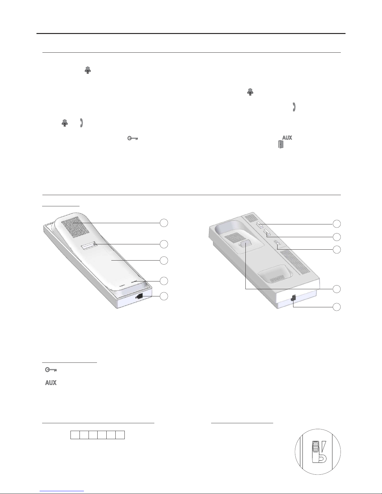
Description of the telephone............................................................................................................................................
................................................................................................................................................................. 3.
Description
............................................................................................................................................... ..3........ .Function buttons
............................................................................................................................................... 3....Connection terminals
................................................................................................................................. . 3................... .Call volume control
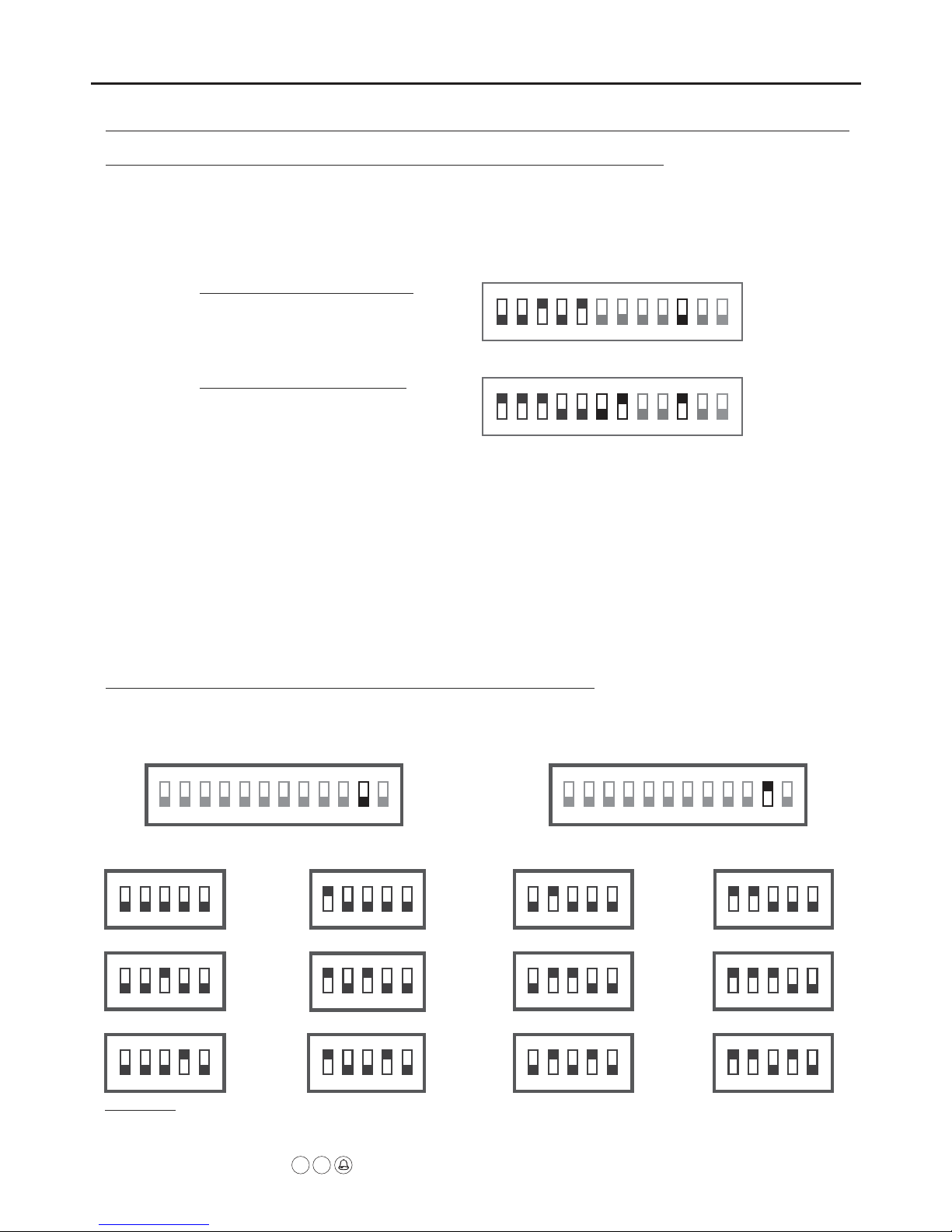
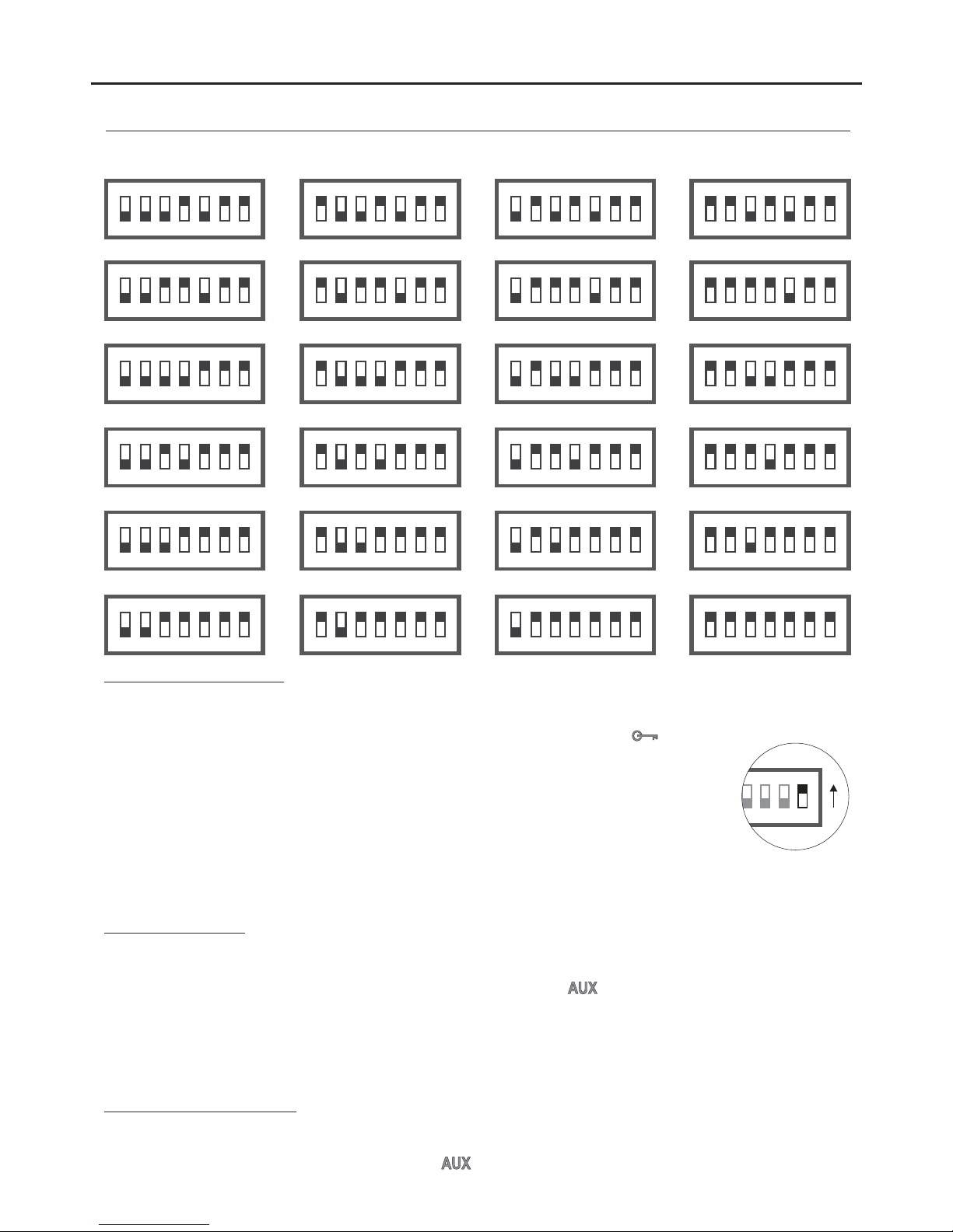
................................................................................................................................ .4............Configuration DIP switch
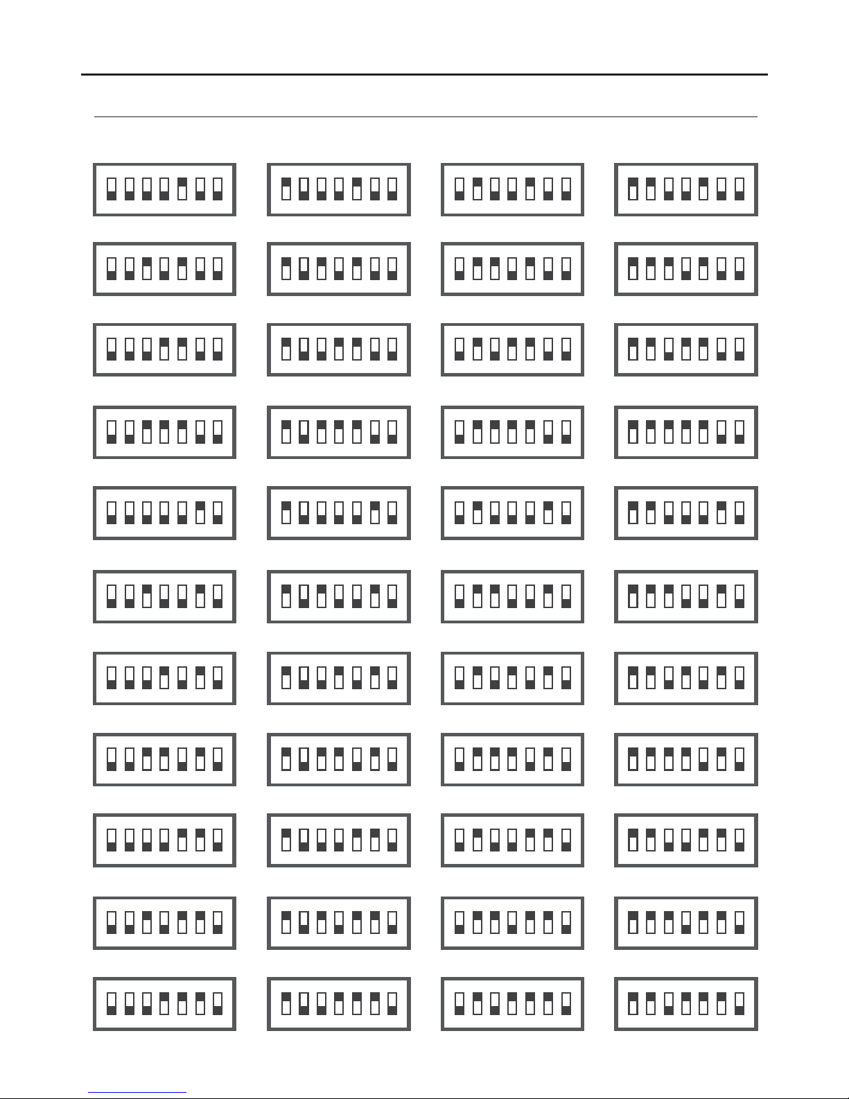
.............................................................. .......4-5..........Configuration of telephone address codes (up to 32 addresses)
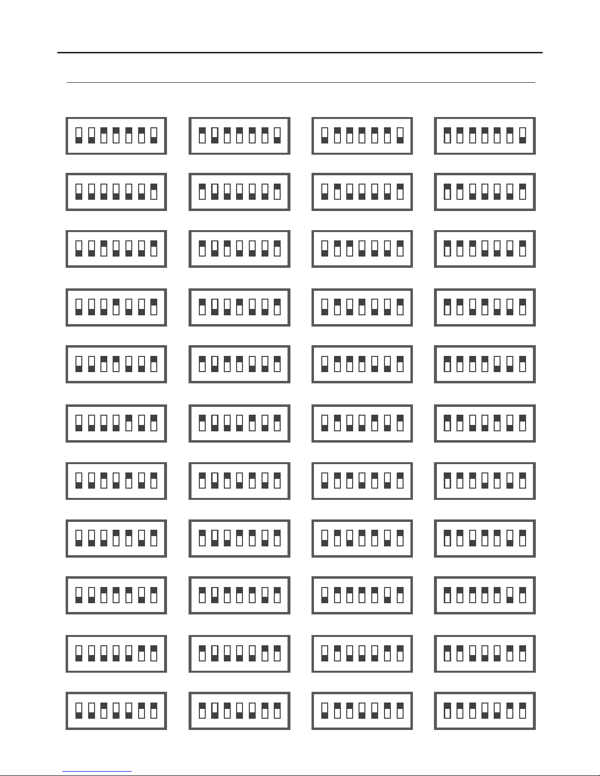
........................................................... ........5-8..........Configuration of telephone address codes (up to 128 addresses)
................................................................................................................................................ 8.'Doctor mode' function
........................................................................................................................................ .8............... .Intercom function
......................................................................................................................8.Light activation function (staircase light)
.................................................................................................................................. 9..........Configuration of ringtones
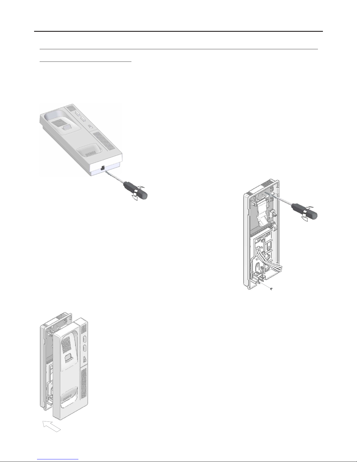
Installing the telephone................................................................................................................................................10
Wiring diagrams...................................................................................................................................... .. 11-12............. .
Notes.......................................................................................................................................................................... 13.
T562 GB2 TELEPHONE
CHARACTERISTICS
-Telephone with simplified wiring (non-polarised 2 wire bus).
-Up to 4 telephones/monitors per apartment (master, slave 1, slave 2 and slave 3).
-Up to 32 apartments/telephones per installation.
-Up to 128 apartments/telephones per installation and maximum 1 telephone per apartment (EL632 GB2A/EL642 GB2A
sound module required).
-Completely private conversation.
-Call volume control (high, medium or mute).
-Input for calls from the interior door of the apartment.
-Call repeater output (SAR-12/24).
-Different ringtones to identify the origin of the call (door panel, intercom or apartment door).
-Button for lock release 1 activation.
-Button for intercom/lock release 2/light activation (SAR-GB2 and SAR-12/24 modules required). Important: Light
activation function only with T-562 telephones V.03 and later.
-Button for configuring ringtones (inside the telephone).
-DIP switches for configuring telephone address (call code), master/slave and end of line and activating 'doctor mode'
function (automatic door opening). Inside the telephone.