golmar T562 GB2 User manual

4
*
( )
TELÉFONO T562 GB2
Cód. 501215Web 99 T G 2 ES562 B GR REV.0 11 6
Golmar se reserva el derecho a cualquier modificación sin previo aviso.
Golmar se réserve le droit de toute modification sans préavis .
Golmar reserves the right to make any modifications without prior notice.
GUÍA RÁPIDA
golmar@golmar.es www.golmar.es
Sistemas de comunicación S.A.
TELÉFONO T562 GB2
INSTALACIÓN DEL TELÉFONO
*
( )
Abrir el teléfono, realizando levemente palanca
con un destornillador plano en las ranuras
dispuestas para ello, como muestra el dibujo.
Para la sujeción directa a pared, realizar dos
taladros de 6mm. en las posiciones especificadas,
utilizando tacos de 6mm. y tornillos Ø3,5 x 25mm.
Pasar los cables por el orificio dispuesto a tal efecto, y
conectarlos a la regleta. Cerrar el teléfono tal y como
muestra el dibujo. Una vez cerrado, conectar el
auricular mediante el cordón telefónico y colocarlo en
la posición de colgado.
Evitar emplazamientos cercanos a fuentes de calor, polvorientos o con mucho humo. El
teléfono puede fijarse en caja universal, o directamente a pared.
Instalación con 32 viviendas/teléfonos T562 GB2 y abrepuertas de continua Golmar.
Placa de acceso
NA2
+AP-
C1 NA1 AP+ C2 AP+ AP- P1 P2 BUSBUS
Relé 2
Relé 1
_
12Vdc
Abrepuertas
máx. 12 Vcc/270mA.
ON
1 2 3 4 5 6
AP
SW1
CÓDIGO 0
Trenzado 2x0.75mm
Trenzado 2x1mm
60m
A
60m
B
80m 80m
Cable manguera
2
2
10m
C
15m
IMPORTANTE: Configurar los
microinterruptores tal como
se indica en el dibujo.
*
( ) *
( )
ESQUEMA DE INSTALACIÓN
CÓDIGO 31
Distanc Sec :ias y ciones
T562
A
C
B
L1 L2
T-562 GB2
L1 L2
T-562 GB2
PrincipalPrincipal
Para más información ver manual de usuario “T562 GB2 (cód. 50121599)”.
https://doc.golmar.es/search/manual/50121599
*
( )
T562
50121895
FA- 2GB /A
Red
100~240Vac
N L
CN
BUS (M) BUS(PL)
FA- 2GB /A
L

2
PRECAUCIONES DE SEGURIDAD
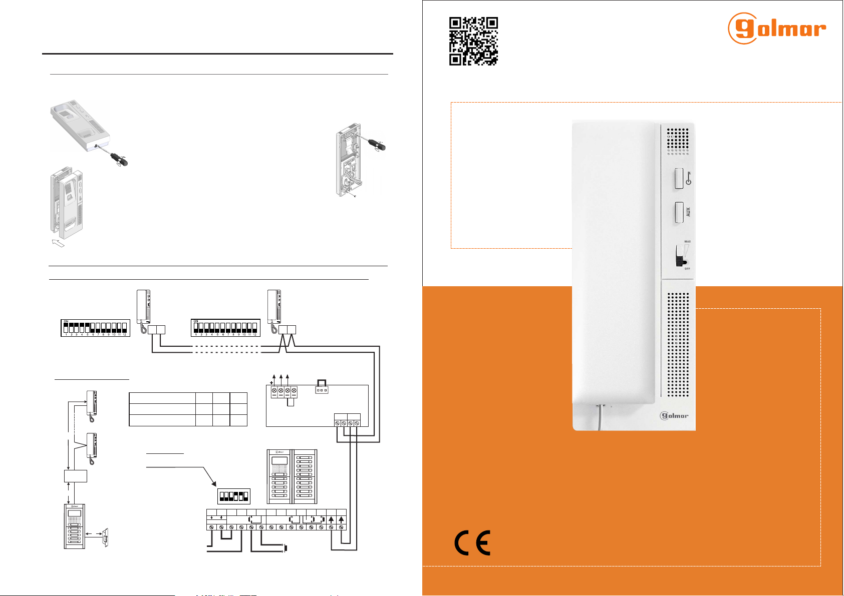
- Teléfono con instalación simplificada (bus de 2 hilos no polarizados).
- Hasta 4 teléfonos/monitores por vivienda (principal, secundario1, secundario 2 y secundario 3).
- Hasta 32 viviendas/teléfonos por instalación.
- Secreto total de conversación.
- Regulador de volumen de llamada (máximo, medio y sin volumen).
- Entrada para llamada desde la puerta interior de la vivienda.
- Salida a sonería auxiliar.
- Tonos de llamada diferenciados, para identificar la procedencia de la llamada: placa, intercomunicación
y puerta interior de la vivienda.
- Pulsador de activación abrepuertas 1.
- Pulsador de intercomunicación / activación abrepuertas 2 / activación luz (requiere módulo SAR-GB2 y
SAR-12/24). Importante:La función activación luz sólo con teléfonos T-562 con V.03 y posteriores.
- Pulsador para configurar los tonos de llamada (en el interior del teléfono).
- Microinterruptores para configurar la dirección del teléfono (código de llamada), principal/secundario,
final de línea y activar la función "modo doctor" (en el interior del teléfono).
- Cuando se instale o modifique el equipo, hacerlo sin alimentación.
- La instalación y manipulación de estos equipos deben ser realizado por personal autorizado.
- Toda la instalación debe viajar al menos a 40 cm. de cualquier otra instalación.
- No apretar excesivamente los tornillos de la regleta.
- Instale el teléfono en un lugar seco y protegido sin riesgo de goteo o proyecciones de agua.
- Evite emplazamientos cercanos a fuentes de calor, húmedos, polvorientos o con mucho humo.
-Antes de conectar el equipo, verificar el conexionado entre placa, alimentador y teléfonos.
- Siga en todo momento las instrucciones de este manual.
CARACTERÍSTICAS
FUNCIONAMIENTO DEL SISTEMA
- Para realizar la llamada, el visitante deberá presionar el pulsador correspondiente a la vivienda
con la que desea establecer comunicación; un tono acústico advertirá de que la llamada se está
realizando y el led de la placa se iluminará. Si la síntesis de voz está habilitada el mensaje
“llamando”nos indicará que la llamada se está realizando. En ese instante, el teléfono(s) de la
vivienda recibe(n) la llamada. Si se ha presionado por equivocación el pulsador de otra vivienda,
pulsar sobre el que corresponda de la vivienda deseada, cancelando así la primera llamada.
- La llamada tiene una duración de 40 segundos. Si la llamada no es atendida antes de 40
segundos, el led se apagará y el canal quedará libre.
- Para establecer comunicación, descolgar el auricular de cualquier teléfono de la vivienda, el led de la
placa se iluminará.
- La comunicación tendrá una duración de un minuto y medio o hasta colgar el auricular. Finalizada
la comunicación, los leds y se apagarán y el canal quedará libre. Si la síntesis de voz está
habilitada, el mensaje “llamada finalizada”nos indicará en la placa que la llamada ha finalizado.
- Si se desea abrir la puerta, presionar el pulsador (si existe y desea abrir la 2ª puerta presione el
pulsador ) durante los procesos de llamada o comunicación: una sola pulsación activa el
abrepuertas durante cinco segundos, el led de la placa se iluminará también durante cinco segundos.
Si la síntesis de voz está habilitada, el mensaje “puerta abierta”nos será indicado en la placa.
- La descripción de los pulsadores de función se encuentran en la página 3.
*
( )
*
( ) Para más información ver manual de usuario “T562 GB2 (cód. 50121599)”.
https://doc.golmar.es/search/manual/50121599
3
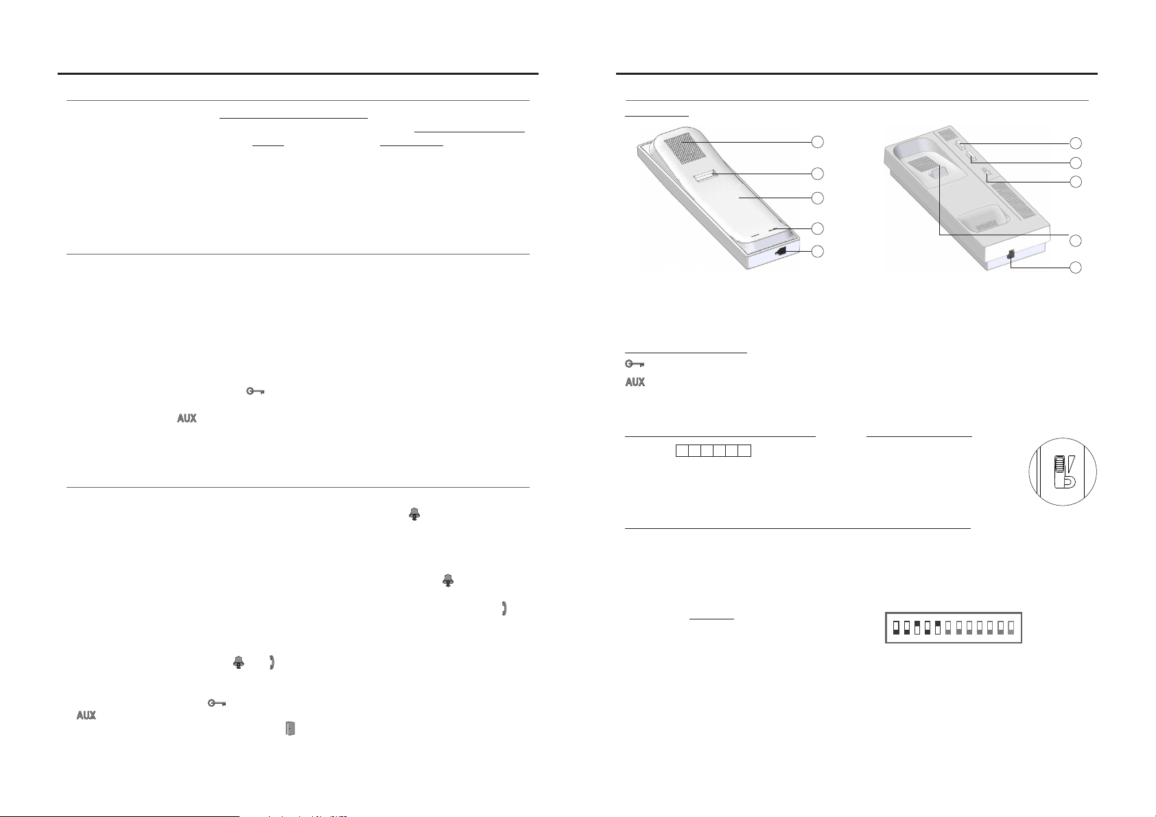
DESCRIPCIÓN DEL TELÉFONO
*
( )
Durante los procesos de recepción de llamada o comunicación, permite activar el abrepuertas 1.
Durante los procesos de recepción de llamada o comunicación, permite activar el abrepuertas 2.
Sistema en reposo:
- Con el auricular descolgado realiza la función de intercom.
- Con el auricular colgado activa la función luz (requiere los módulos SAR-GB2 y SAR-12/24).
Pulsadores de función:
Regulación volumen de llamada:
*
( ) Para más información ver manual de usuario “T562 GB2 (cód. 50121599)”.
https://doc.golmar.es/search/manual/50121599
TELÉFONO T562 GB2 TELÉFONO T562 GB2
a
d
c
e
b
g
e
a.
b.
c.
d.
e.
Brazo auricular.
Rejilla difusión sonido.
Orificio micrófono.
Hueco de sujeción.
Conectores para cordón telefónico.
f
h
i
Pulsador de abrepuertas.
Pulsador de colgado.
Pulsador de función auxiliar.
Regulación de volumen.
f.
g.
h.
i.
MAX
OFF
El teléfono permite elregular
volumen de llamada con un
valor máximo, medio o sin
volumen.
Descripción microinterruptor y configuración dirección (código) teléfono:
*
( )
123
ON
Ejemplo: 0 + 0+ 4+0+16 = 20
Interruptor nº: 1 2 3 4 5
Valor en ON: 1 2 4 8 16
Tabla de valores
4 5 6
Dip1 a Dip5: Con!gurar la dirección del teléfono (dirección 0 a 31).
Dip6 y Dip7: Dejar en OFF.
Los interruptores colocados en la posición OFF tienen valor cero.
En la posición ON tienen asignados los valores de la tabla adjunta.
El código del teléfono será igual a la suma de valores de los interruptores colocados en ON.
Dip8 y Dip9: Con!gura el teléfono como principal/secundario. Dip8 y Dip9 a OFF principal, Dip8 a ON y Dip9 a OFF
secundario 1, Dip8 a OFF y Dip9 a ON secundario 2, Dip8 y Dip9 a ON secundario 3.
Dip10: Dejar en OFF.
Dip11: Con!gura el !nal de línea. En instalaciones con sólo teléfonos debe estar siempre en OFF. En
instalaciones mixtas de monitores con teléfonos en la misma vivienda, colocar en ON en aquellos teléfonos en
los que acabe el recorrido del cable del bus y dejar en OFF sólo en teléfonos intermedios.
Dip12: Dejar en OFF de!ne como "sin volumen" la posición OFF del interruptor de regulación de volumen.
Poner a ON de!ne como función "modo doctor" la posición OFF del interruptor de regulación de volumen.
Descripción bornes de conexión:
Conexión Bus.
Conexión a timbre de puerta.
Conexión sonería auxiliar, (SAR-12/24).
(12Vcc/50mA máximo).
L1 L2, :
HZ , :
SA , :
SAL1 L2 _
HZ _
_
_
7 8 9 10 11 12
Descripción:

4
*
( )
T562 TEL ONGB2 EPH E
QUICK GUIDE
T562 G 2B TELEPHONE
TELEPHONE INSTALLATION
*
( )
To open the telephone ainsert plain
screwdriver and gently asinto the slots lever
shown in the d .rawing
To secure directly to the wall, drill two 6mm. holes at
the specified positions. Use 6mm. wall plugs and
Ø3.5 x 25mm screws.
Pass the installation wires through the corresponding
hole and connect them to the terminal block. Close
the telephone as shown on the picture. Once the
telephone is closed, connect the handset using the
telephone cord and put it on the cradle.
Avoid placing the telephone near sources of heat, in dusty locations or smoky environments.The
telephone can be secured using an electrical embedding box or directly to the wall.
Installation for 32 apartments/T562 GB2 telephones and Golmar D.C. lock release.
Access paneldoor
NA2
+AP-
C1 NA1 AP+ C2 AP+ AP- P1 P2 BUSBUS
Relay 2
Relay 1
_
12Vdc
Lock release
max. 12 Vdc/270mA.
ON
1 2 3 4 5 6
AP
SW1
CODE 0
Twisted pair 2x0.75mm
Twisted pair 2x1mm
60m
A
60m
B
80m 80m
Cable
2
2
10m
C
15m
IMPORTANT: Configure the
dip switch as shown in the
diagram.
*
( ) *
( )
INSTALLATION DIAGRAM
CO 31DE
Distances and Cross-Sections:
T562
A
C
B
L1 L2
T-562 GB2
L1 L2
T-562 GB2
MasterMaster
For further information see the “T562 GB2 (code 50121599)”user manual.
https://doc.golmar.es/search/manual/50121599
*
( )
T562
C d. 501215o Web 99 T G 2 E562 B N GR REV.0 11 6
Golmar se reserva el derecho a cualquier modificación sin previo aviso.
Golmar se réserve le droit de toute modification sans préavis .
Golmar reserves the right to make any modifications without prior notice.
golmar@golmar.es www.golmar.es
50121895
Sistemas de comunicación S.A.
FA- 2GB /A
Main
100~240Vac
N L
CN
BUS (M) BUS(PL)
FA- 2GB /A
L

2
SAFETY PRECAUTIONS
- Telephone with simple installation (2 wire BUS ).without polarity
- Up to 4 telephones/monitors per apartment (master, slave 1, slave 2 and slave 3).
- Up to 32 apartments/telephones per installation.
- Completely private conversation.
- Call volume control (maximum, medium and mute).
- Input for calls from the apartment's door.
- Call repeater output.
- Different ring tones indicate the origin of the call: door panel, intercom and apartment door.
- Lock release push button1 activation .
- 2 / activation light function "stairs light" (it requires of SAR-GB2 & SAR-12/24Intercom/lock release
modules) .push button Note:The light function only with T562 Telephones with V.03 or later.
- .Push button for setting ring tones (inside the telephone)
- Dip switches for setting the telephone address (call code), master/slave, end of line and activating the
“doctor mode”(inside the telephone).
- Install or modify the equipment without the power connected.
- The installation and handling of these equipments must be performed by authorised personnel.
- entire installation must beThe at least away from any other40 cm installation.
- Do not overtighten the screws on the terminal block.
- and place without risk of drop or water projectionsInstall the telephone in a dry protected .
-Avoid to place it near to heating sources, in dusty locations or smoky enviroments.
- Before connecting the system to the mains, check the connections between the door panel,
power supply and telephones.
- Do a the enclosed informationlways follow .
CHARACTERISTICS
SYSTEM OPERATION
- To make a call the visitor should press the button corresponding to the desired apartment; an
audible tone indicates that the call is being made and the will turn on. If thedoor panel LED
vocal synthesis is the “call ”willenabled message is in progress be heard confirming the call is in
progress. At this moment the apartment's telephone(s) receive(s) the call. During the call the
visitor can correct his call by pressing a push button corresponding to a different apartment, in
which case the original call is cancelled.
- The call lasts for 40 seconds. If the call is not answered within 40 seconds, the LED will turn off
and the channel will be freed.
- To establish communication, lift the handset of any telephone in the apartment. The door panel LED
will turn on. If the vocal synthesis is enabled the message "you can speak now" will be heard confiming
the communication is activated
- The communication will last for one and a half minutes or until the handset is replaced. When
communication has finished the and LEDs will turn off and the channel will be freed. If the
vocal synthesis is the “c”willenabled message ommunication is finished be heard in the door
panel confirming the communication has finished.
- To open the door, press the push button (to open the second door, if there is one, press the
....... push button) during the call or communication processes: one press will activate the lock
release for five seconds and the LED will also turn on during this time. If the vocaldoor panel
synthesis is the “door open”will be on the door panel.enabled message is heard
- The descriptions of the function push buttons are found on page 3.
*
( )
*
( ) For further information see the “T562 GB2 (code 50121599)”user manual.
https://doc.golmar.es/search/manual/50121599
3
TELEPHONE DESCRIPTION
*
( )
Activates lock release 1 during the call reception and communication processes.
Activates lock release 2 during the call reception and communication processes.
During standby:
- .With the handset lifted it enables intercom functionality
- With the handset on the craddle it enables light function (it requires SAR-GB2 & SAR-12/24 modules).
Function push buttons:
Call volume control:
*
( ) For further information see the ode user manual“T562 GB2 (c . 50121599)”.
https://doc.golmar.es/search/manual/50121599
T562 G 2B TELEPHONE T562 G 2B TELEPHONE
a
d
c
e
b
g
e
a.
b.
c.
d.
e.
Handset.
Speaker grille.
Microphone hole.
Subjection hole.
Telephone cord connectors.
f
h
i
Lock release push button.
Hook switch.
Auxiliary function push button.
Volume control.
f.
g.
h.
i.
MAX
OFF
The telephone has a call
volume control which can
be set to maximum, medium
or mute.
Description of dip switch and setting of telephone address (code):
*
( )
123
ON
E : 0 + 0 +4+0+16 = 20xample
Switch number: 1 2 3 4 5
1 2 4 8 16Value ON:
Value chart
4 5 6
Dip1 Dip5:to Set the telephone address (addresses 0 to 31).
Dip6 Dip7:and OFF.Leave
Switches set to OFF have a value of zero.
The values of the switches set to ON are shown in the enclosed chart.
The telephone code will be the sum of the values of the switches set to ON.
Dip8 Dip9:and Set the telephone as master/slave. Dip8 and Dip9 OFF, master; Dip8 ON and Dip9 OFF, slave 1;
Dip8 OFF and Dip9 ON, slave 2; Dip8 and Dip9 ON, slave 3.
Dip10: OFF.Leave
Dip11: Sets the end of line It should always be set to OFF in installations with only telephones. In installations with.
monitors and telephones in the same apartment, set to ON for the telephones at which the BUS cable ends, and
set to OFF for intermediate telephones.
Dip12: " "Setting this to OFF makes the volume control's OFF position function as mute .
Setting this to ON makes the volume control's OFF position function as doctor mode ." "
Description of connection terminals:
BUS connection.
Door bell push button connection.
Call repeater connection, (SAR-12/24).
(12V c/50mA m xim ).d a um
L1 L2, :
HZ , :
SA , :
SAL1 L2 _
HZ _
_
_
7 8 9 10 11 12
Descrip :tion

4
*
( )
T T 562ELEFOONTOESTEL - GB2
C d. 501215o Web 99 T G 2562 B GRNL REV.0 11 6
Golmar se reserva el derecho a cualquier modificación sin previo aviso.
Golmar se réserve le droit de toute modification sans préavis .
Golmar reserves the right to make any modifications without prior notice.
SNEL HANDLEIDING
golmar@golmar.es www.golmar.es
Sistemas de comunicación S.A.
PLAATSEN VAN DE TELEFOON
*
( )
Het openen van de telefoon:
Steek een platte schroevendraaier in de
gleuf aan de onderzijde en open voorzichtig
zoals aangegeven in de tekening.
Het anders openen van het toestel dan op
deze wijze kan schade aan de
volumeregelaar toebrengen.
Om de telefoon direct op de muur te
monteren, boor twee gaten van 6mm. op de
aangegeven plaatsen.
Bevestig de telefoon met behulp van 6mm.
pluggen en 3,5 x 25mm schroeven.
Voer de bekabeling door het corresponderende gat
en sluit deze aan. Sluit de telefoon als op de foto.
Zodra de telefoon is aangesloten, sluit u de hoorn
aan met behulp van het telefoonsnoer en zet hem op de houder.
Let op dat u het telefoonsnoer er goed in klikt met een hoorbare klik.
Vermijd plaatsing in de buurt van warmte bronnen en of plaatsing in een stoffige of rokerige ruimte. De
telefoon kan op een standaard inbouwdoos worden bevestigd of direct op de muur.
Instal / T 562 GB2latie met 32 appartementen deurtelefoons - en gelijkspannings deuropener
van Golmar:
Buitendeurpaneel
NA2
+AP-
C1 NA1 AP+ C2 AP+ AP- P1 P2 BUSBUS
Relé 2
Relé 1
_
12Vdc
Deuropener
m x. 12 V c/270mA.a d
ON
1 2 3 4 5 6
AP
SW1
C 0ODE
T 2x0.75mmwisting
T 2x1mmwisting
60m
A
60m
B
80m 80m
Kabel diameters
2
2
10m
C
15m
BELANGRIJK: Dipswitchen
zo instellen voor enkele
beldrukker panelen.
*
( ) *
( )
INSTALLATIE SCHEMA
C 31ODE
Afstanden en diameters:
T562
A
C
B
L1 L2
T-562 GB2
L1 L2
T-562 GB2
MasterMaster
Voor meer informatie zie de handleiding “T562 GB2 (cód. 50121599)”.
https://doc.golmar.es/search/manual/50121599
*
( )
T562
TELEFOONTOESTEL T-562 GB2
50121895
FA- 2GB /A
Main
100~240Vac
N L
CN
BUS (M) BUS(PL)
FA- 2GB /A
L

2
VEILIGHEIDSWAARSCHUWING
- ( ).Vereenvoudigde installatie 2-draads ongepolariseerde BUS
- Tot 4 telefoons/monitoren per appartement/woning Master, Slave1, Slave2 en Slave3)( ).
- Tot 32 appartementen/telefoons per installatie.
- Geheim gesprek.
- Volumeregelaar maximaal, minimaal en geen geluid( ).
- Etagesignaal.
- Uitgang vaar parallelsignaal (SAR-12/24).
- Verschillende oproepsignalen buitendeurpaneel, etagesignaal en intercom( ).
- Deuropenertoets voor het opensturen van de deur tijdens het gesprek .
- Met optietoets : Mogelijkheid tot Intercom/deuropener 2/activering licht functie “trappenhuis
verlichting”(hiervoor zijn de SAR-GB2 & SAR 12/24 module nodig).- Belangrijk: De functie
activering licht kan alleen met een T652 deurtelefoon versie V0.3 of later.
- Microschakelaar om de beltonen in te stellen bevind zich in de binnenkant van de telefoon( ).
- Dipswitchen voor het instellen van code/adres van de telefoon master slave eindweerstand en( ), / ,
de doktersfunctie automatisch deuropenen bij aanbellen bevind zich in de binnenkant van" " ( ).
de telefoon.
- Installeren of aanpassen van de installatie altijd spanningsloos te gebeuren.
-Installeren of plaatsen van de apparatuur dient te gebeuren door een erkende installateur.
-De installatie dient minimaal verwijdert te zijn van40 cm andere installaties.
- Volg altijd de instructies in deze handleiding.
wGebruik geen extreme krachten om de schroeven aan te draaien.
wI eer d apparatuur een droge stofvrije ruimte en voorkom dat er waterdruppels doornstall e in
lekkage bij kunnen.
wVermijd plaatsing van de apparatuur in de nabijheid van warmtebronnen.
wLaat de ventilatie roosters vrij voor een goede ventilatie.
wOm schade te voorkomen dient de voeding juist en stevig geplaatst te worden.
wVoorkom een elektrische schok en laat de beschermkap over de 230 volt aansluiting van de
voeding.
EIGENSCHAPPEN
WERKING VAN HET SYSTEEM
- ;Om een oproep te plaatsen, druk op de beldrukker behorende bij het appartement een
akoestische toon zal hoorbaar zijn ter bevestiging dat de beldrukker is ingedrukt en de LED zal
gaan branden. Indien de spraak synthese actief is zal u heeft aangebeld hoorbaar zijn De“ ” .
oproep zal nu in het appartement worden ontvangen Gedurende de oproep kan de bezoeker.
zijn oproep corrigeren door op de juiste beldrukker te drukker de eerdere oproep wordt dan,
geannuleerd.
- .Een oproep duurt 40 seconden Indien de oproep niet binnen de 40 seconden wordt beantwoord
zal de LED uitgaan en is het systeem weer in rust.
- Om een oproep te beantwoorden, neem de hoorn van de haak, de LED zal gaan branden.
- De communicatie duurt 1½ minuut of totdat de hoorn wordt teruggeplaatst. Na het beëindigen
van het gesprek zullen de LED’s en uitgaan en is het systeem weer in rust. Indien de
spraaksynthese is geactiveerd zal de tekst „gesprek is beëindigd“hoorbaar zijn.
- Om de deur te openen druk op de deuropenertoets indien een e deuropener aanwezig is( 2
kan men op de toets drukken tijdens het gesprek met 1 korte druk op een van deze toetsen) :
zal de gewenste deur voor 5 seconden worden open gestuurd en zal de LED gaan branden.
- De beschrijving van de functietoetsen bevindt zich op pagina 3.
*
( )
*
( ) Voor meer informatie zie de handleiding “T562 GB2 (cód. 50121599)”.
https://doc.golmar.es/search/manual/50121599
3
BESCHRIJVING VAN DE TELEFOON
*
( )
Tijdens de oproep en het gesprek kan hiermee de deur geopend worden (deuropener 1).
Tijdens de oproep en het gesprek kan hiermee een tweede deur geopend worden (deuropener2).
Terwijl het systeem in rust:
- kan men een intercom oproep plaatsen indien meerdere telefoons/Met de hoorn opgeheven
monitoren aanwezig.
- Met de hoorn op de haak wordt het relais voor de licht functie geactiveerd (hiervoor zijn de SAR-
GB2 & SAR-12/24 nodig).
Functietoetsen:
Volumeregelaar:
*
( ) Voor meer informatie zie de handleiding “T562 GB2 (cód. 50121599)”.
https://doc.golmar.es/search/manual/50121599
a
d
c
e
b
g
e
a.
b.
c.
d.
e.
Hoorn van de telefoon.
Luidsprekerrooster.
Microfoon gat.
Ophang gat.
Telefoonsnoer connector.
f
h
i
Deuropenertoets.
Hoorn ophang haak/schakelaar.
Optietoets AUX.
Volumeregelaar.
f.
g.
h.
i.
MAX
OFF
Hiermee kan het volume van
de oproep worden
aangepast in maximaal,
minimaal en geen geluid.
Beschrijving van de dipswitchen en configuratie odering van de telefoon(c ) :
*
( )
123
ON
Voorbeeld: 0 + 0+ 4+0+16 = 20
Dipswitch nº: 1 2 3 4 5
ON: 1 2 4 8 16Waarde
Waardentabel
4 5 6
Dip 1 Dip 5:switch tot switch ( 0 31).Stel hiermee het adres/code in van de telefoon adres/code tot
Dip 6 Dip 7:switch en switch OFF .Op laten staan
De switchen in de OFF positie hebben de waarde 0.
In de stand ON worden de waarden toegewezen als in onderstaande tabel.
De adressering/codering van de telefoon is gelijk aan de waarden van de dipswitchen in de positieON .
Dip 8 Dip 9:switch en switch Con!guratie Master/Slave volgorde. Master (dipswitch 8 en dipswitch 9 op OFF),
slave 1 (dipswitch 8 op ON en dipswitch 9 op OFF), slave 2 (dipswitch 8 op OFF en dipswitch 9 op ON) en voor
slave 3 (dipswitch 8 en dipswitch 9 op ON).
Dip 10:switch Op OFF laten staan.
Dip 11:switch Hiermee kan de eindweerstand worden ingesteld. In installaties met alleen telefoons kan de op
OFF blijven staan, indien gemixt met monitoren en bij gebruik splitters dient elke laatste monitor of telefoon als
eind te worden ingesteld en moet deze switch op ON staan.
Dip12: OFF .Op laten staan. Als de volumeregelaar in de UIT positie staat zal het volume uit staan
Indien dipswitch 12 op ON en als de volumeregelaar in de OFF positie staat zal direct de deur worden geopend
(doktersfunctie), in de minimaal en maximaal volume stand heeft de telefoon een normale werking .
Beschrijving aansluitklemmen:
Aansluiting BUS.
Aansluiting etagebeldrukker.
Aansluiting voor extra signaalgever,
, d aximaal(SAR-12/24) (12V c/50mA m ).
L1 L2, :
HZ , :
SA , :
SAL1 L2 _
HZ _
_
_
7 8 9 10 11 12
Beschrijving:
TELEFOONTOESTEL T-562 GB2 TELEFOONTOESTEL T-562 GB2
Other manuals for T562 GB2
1
Table of contents
Languages:
Other golmar Telephone manuals

golmar
golmar T562 G2 User manual

golmar
golmar T-ART/G2+ User manual

golmar
golmar GTWIN T-5924 User manual

golmar
golmar T-ART/G2+ User manual

golmar
golmar T-740 Plus User manual

golmar
golmar T-ART/G2+ User manual

golmar
golmar T562 GB2 User manual

golmar
golmar T-540 PLUS SE User manual

golmar
golmar T-790VD User manual

golmar
golmar T-940 XP User manual