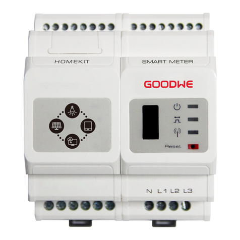
Goodwe GM3000C User manual

(GM3000C)
Quick Installation Guide
Smart Meter
V1.0-2022-11-09

7
Quick Installation Guide V1.0 -2022 -11-09
• Informace v tomto stručném průvodci instalací se mohou změnit v důsledku aktualizací
výrobku nebo jiných důvodů. Všechny uvedené popisy slouží pouze pro orientaci.
• Před instalací si pročtěte stručný průvodce instalací.
• Všechny činnosti musí provádět proškolení a kvalikovaní technici, kteří jsou
obeznámeni s místními normami a bezpečnostními předpisy.
• Zkontrolujte dodávku, zda obsahuje správný model, všechny součásti a je zvenčí
neporušená. Pokud zjistíte jakékoli poškození nebo scházející součást, kontaktujte
výrobce.
• Důsledně dodržujte pokyny k instalaci, provozu a konguraci uvedené v tomto průvodci
a uživatelské příručce. Výrobce nenese odpovědnost za poškození zařízení ani zranění
osob v případě nedodržení pokynů. Podrobnosti o záruce najdete na stránce https://
en.goodwe.com/warranty.
Bezpečnostní opatření
Obecné prohlášení o vyloučení odpovědnosti
01
• Před jakoukoli činností se ujistěte, že je zařízení vypnuté.
• Ujistěte se, že kabely jsou zapojené pevně, bezpečně a správně. Nevhodné zapojení může
způsobit špatný kontakt nebo poškození zařízení.
• Na straně vstupního napětí se doporučuje osadit dodatečné jističe, aby nedošlo ke
zranění osob nebo poškození zařízení.
• Specikace ochranné pojistky musí být 0,5 A.
• Pokud v prostorách s nebezpečím zásahu bleskem přesahuje délka kabelu zařízení 10 m
a kabel je veden bez uzemněných kovových trubek, doporučuje se použít externí zařízení
na ochranu proti blesku.
Prohlášení o bezpečnosti
VAROVÁNÍ
Zkontrolujte před zapnutím
Č. Kontrolovaná součást
1Výrobek je pevně nainstalován na čistém místě, které je dobře větrané a snadno
přístupné.
2Vstupní napájecí kabely, CT kabely a komunikační kabely jsou správně
a bezpečně zapojené.
3Kabelové svazky jsou neporušené, správně a rovnoměrně vedené.
CS

8
Quick Installation Guide V1.0 -2022 -11-09
Skladování
Pokud zařízení nebudete ihned instalovat nebo používat, dbejte na to, aby skladovací
podmínky vyhovovaly následujícím požadavkům:
• Nerozbalujte vnější obal ani nevyhazujte vysoušecí činidlo.
• Zařízení skladujte na čistém místě. Zajistěte v místě vhodnou teplotu a vlhkost a aby
nedocházelo ke kondenzaci.
• Pokud byl chytrý měřič dlouhodobě uskladněn, musí ho před uvedením do provozu
zkontrolovat odborníci.
Modul prodávaný na evropském trhu vyhovuje následujícím směrnicím a požadavkům:
• Směrnice 2014/30/EU o elektromagnetické kompatibilitě (EMK)
• Směrnice 2014/35/EU o zařízeních nízkého napětí (LVD)
• Směrnice 2011/65/EU a (EU) 2015/863 o omezení používání některých nebezpečných látek
(RoHS)
• Směrnice 2012/19/EU o odpadních elektrických a elektronických zařízeních
• Nařízení (ES) č. 1907/2006 o registraci, hodnocení, povolování a omezování chemických
látek (REACH)
EU prohlášení o shodě si můžete stáhnout na stránce https://en.goodwe.com.
EU prohlášení o shodě
02

9
Quick Installation Guide V1.0 -2022 -11-09
Technické parametry
03
Model GM3000C
Vstup
Síť Tři fáze
Napětí
Jmenovité napětí – linka k N (Vac) 230
Jmenovité napětí mezi linkami
(Vac) 400
Rozsah napětí 0,88 Un – 1,1 Un
Jmenovitá frekvence stř. napájecí
sítě (Hz) 50/60
Proud
Poměr proudového
transformátoru nA:5 A
Počet proudových transformátorů /
Komunikace RS485
Komunikační vzdálenost (m) 1 000
Bezdrátový
parametr Podporované standardy a frekvence /
Uživatelské rozhraní 3 LED, tlačítko Reset
Přesnost
Napětí/proud Třída 1
Činná energie Třída 1
Jalová energie Třída 2
Příkon (W) <3
Mechanické
Rozměry (Š × V × H mm) 72*85*66,5
Kryt 4 moduly
Hmotnost (g) 200
Uchycení DIN lišta
Prostředí
Stupeň ochrany krytem IP20
Rozsah provozních teplot (°C) -25~60
Rozsah skladovacích teplot (°C) - 30~70
Relativní vlhkost (nekondenzující) 0~95 %
Max. provozní nadmořská výška (m) 2000

67
Quick Installation Guide V1.0 -2022 -11-09
Product Introduction
04 Introduction
Indicators
USB Port
Reset Button
NO. Component Description
1 Normal status: ON
2Consuming: ON
Generating: Blinking
3Blink once detecting data transfering
Blink 5 times as Reset succeeds
4
Press less than 3 s: Meter Reset
Press 5s more or less: Meter Settings Initialization
Press more than 10 s: Meter Initialize settings and Clear Energy Data
5 USB port For after-sales maintenance.
A: RS485+
B: RS485-
85mm
72mm
66.5mm
I1 +
I1 -
I2 +
I2 -
I3 +
I3 -
N9
10 L1
11 L2
12 L3

68
Quick Installation Guide V1.0 -2022 -11-09
Installation
05
Packing List
Smart Meter x 1 Screwdriver x 1 Documents x 1
Wiring
Terminals x 18
Installing the Meter and Cable Connection
1
1
24
3
5
5
6
NOTICE
• The meter is installed on a rail, and should not be installed outdoors.
• When operating the meter, use insulation tools and wear personal protective
equipment to ensure personal safety.

69
Quick Installation Guide V1.0 -2022 -11-09
Connect CT cables
NOTICE
• Requirements for the external CT specications:
1. Choose nA/5A for the current transformation ratio of the external CT. (n: CT primary
input current value between 200 - 5000, which is chosen by the user according to
the actual conditions.
5A: CT secondary output current.)
2. Sampling error for the CT current ≤1% (0.5, 0.5s, 0.2, 0.2s is recommended).
3. CT bore size must be greater than the outer diameter of AC power line to make sure
the AC power line can be inserted through CT.
4. It is recommended to choose the CT with 16AWG cable.
5. See the instructions provided by the respective manufacturer for specic CT
wirings to ensure that the direction of the connections is correct and that they are
functioning properly.
• An incorrect inlet or direction from the external CT to the meter cable can cause
damage to the device or incorrect acquisition of data.
• Do not tamper with the cables that are pre-installed with the meter.
• The direction of the external CT is from P1 end to P2 end, and the corresponding AC
power line direction is from inverter side to grid side.
• It is recommended to add an overcurrent protection device (rated current 0.5A) to the
voltage input terminal (L1/L2/L3) of the meter.
S2 S1
P2 S2 S1
P2
S2 S1
P2
1
1
24
55
5
5
6
6
3

70
Quick Installation Guide V1.0 -2022 -11-09
Wiring System
06
System comprised of a single three-phase unit
CT direction: House (K)-->Grid (L).
Loads
Fuse
Household
Meter
Utility
Grid
Inverter
PV
RS485+
External CT
RS485-
+-
L1
L2
L3
N

71
Quick Installation Guide V1.0 -2022 -11-09
Inverter N
Loads
Utility Grid
Household
Meter
CT direction: House (K)-->Grid (L).
System comprised of multiple three-phase units
Inverter 1
PV N PV 1
External CT
Ezlogger Pro
Fuse
RS485+ RS485- RS485+
RS485-
Router
Monitoring
System
L1
L2
L3
N
......

72
Quick Installation Guide V1.0 -2022 -11-09
Commissioning
07
Step 1 Connect the meter cables.
Step 2 Power on the inverter and make sure that the inverter is working normally. Then the
meter is powered on.
Set the CT parameters using the SolarGo APP (system comprised of a single three-
phase unit,with the Export function enabled)
NOTICE
Before setting the parameters, make sure that:
1. The DC side of the inverter is powered on, but no output on the AC side.
2. The SolarGo APP has been downloaded from Google Play or App Store.
3. Communication is functioning properly between SolarGo APP and inverter.
4. Please use the initial password when logging in for the rst time, and change it as
soon as possible to one that is memorable for you. To keep your account secure, it is
recommended to change your password regularly.
SolarGo App
When the GM3000C is used with the Inverter such as BTC series or ETC series etc., please
refer to the corresponding user manual for CT-related parameter settings.
Power ON
Commissioning the Meter

73
Quick Installation Guide V1.0 -2022 -11-09
12
• Bluetooth: SOL-
BLE********
• WiFi: SOL-WiFi********
• WiFi initial password:
12345678
• Scan the QR Code on the
equipment if you need to
use GPRS or 4G
• * are the last 8 digits of the
inverter SN
3
• Initial password for
Bluetooth/WiFi: 1234
• Initial password for 4G:
automatically ll in
• Initial Password for GPRS:
the last 4 digits of the
inverter bar code
4
5
6

74
Quick Installation Guide V1.0 -2022 -11-09
Set the CT parameters using ProMate (system comprised of multiple inverters)
NOTICE
Before setting the parameters, make sure that:
1. Both EzloggerPro and GM3000C is powered on.
2. GM3000C is correctly connected to COM4 of EzloggerPro via RS485.
3. The Ezlogger Pro Promate software has been downloaded from GOODWE’s ocial
website and installed on the computer.
4. ProMate is connected to EzLogger Pro successfully. For detailed procedures, refer to
the EzLogger Pro Series User Manual.
Descriptions of the Export Function.
1
2
• Total Capacity: Set according to the total capacity of the PV station.
• Power Limit: Set according to the target power that needs to be fed into the grid.
• Ratio of CT: Set according to the CT transformation ratio.

GoodWe Technologies Co., Ltd.
No. 90 Zijin Rd., New District, Suzhou, 215011, China
www.goodwe.com
Ocial Website
Local Contacts
Other manuals for GM3000C
1
Table of contents
Other Goodwe Measuring Instrument manuals

Goodwe
Goodwe GM2000 User manual

Goodwe
Goodwe GMK110 User manual

Goodwe
Goodwe HomeKit User manual

Goodwe
Goodwe HK3000 Original operating instructions

Goodwe
Goodwe HK1000 User manual

Goodwe
Goodwe GM1000D User manual

Goodwe
Goodwe HK1000 User manual

Goodwe
Goodwe HK1000 User manual

Goodwe
Goodwe GMK120 User manual

Goodwe
Goodwe HK3000 Original operating instructions