Grace Company Continuum II Quick setup guide

Copyright September 18, 2020
Grace Company
(Reproduction Prohibited)
Version 1.0
Just purchased your frame?
Save time setting it up by following the instructions in this manual!
12 Foot Frame - Assembly & Use

2
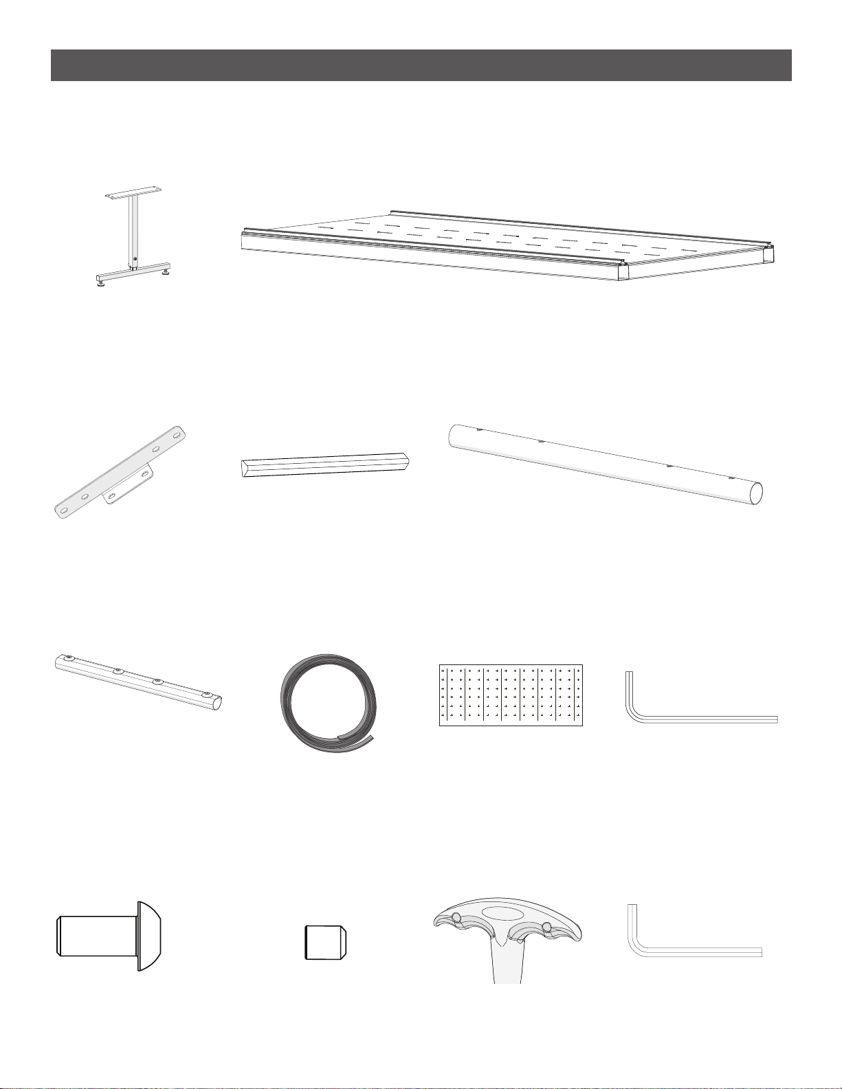
Included Parts & Tools....................................................................................3
Extended Frame Assembly..............................................................................4
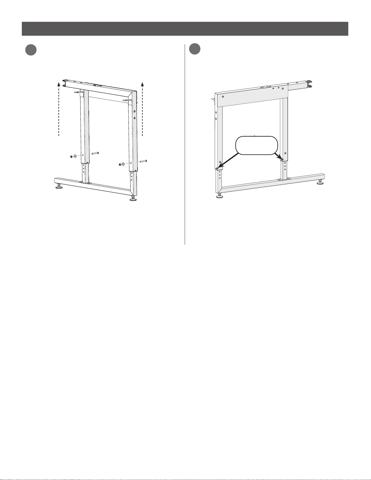
Step 1 - Setting the Frame Height.........................................................................................................5
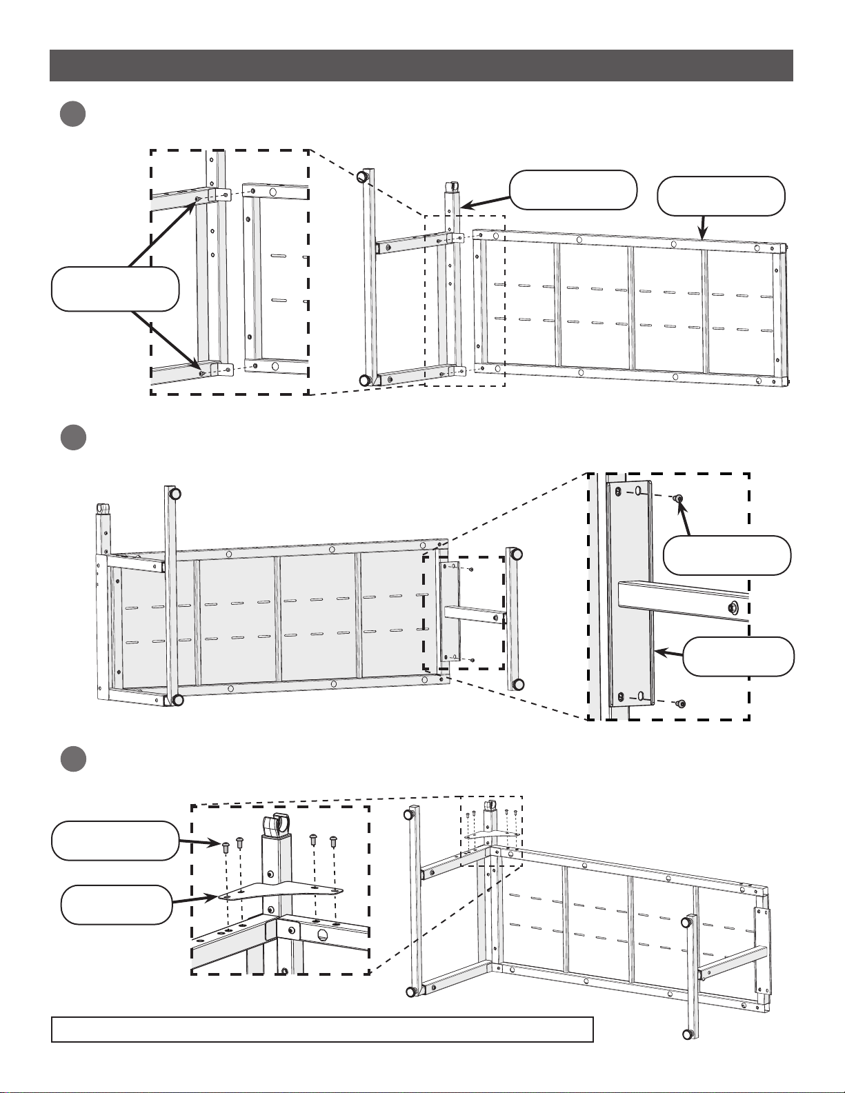
Step 2 - Building the Frame Table ........................................................................................................7
Step 3 - Installing the Tracks.............................................................................................................. 12
Step 4 - Assembling the Rail Supports.............................................................................................. 16
Step 5 - Installing the Bottom Carriage ............................................................................................ 17
Step 6 - Installing the Quilting Machine .......................................................................................... 19
Step 7 - Leveling the Frame................................................................................................................ 21
Step 8 - Installing the Rails................................................................................................................. 23
Step 9 - Assembling the Handwheel.................................................................................................. 29
Step 10 - Installing the Bungee Clamps............................................................................................ 30
Step 11 - Adjusting the Rails .............................................................................................................. 31
Step 12 - Installing the Velcro Tape.................................................................................................. 33
Step 13 - Installing Leader Cloth ...................................................................................................... 36
Upgrade Existing Frame................................................................................38
Step 1 - Rail Assembly......................................................................................................................... 39
Step 2 - Track Assembly...................................................................................................................... 42
Step 3 - Extending the Table............................................................................................................... 47
Step 4 - Installing the Tracks.............................................................................................................. 51
Step 5 - Leveling the Frame................................................................................................................ 53
Step 6 - Installing the Rails................................................................................................................. 55
Step 7 - Adjusting the Rails ................................................................................................................ 57
Step 8 - Installing the Velcro Tape.................................................................................................... 59
Step 9 - Installing Leader Cloth ........................................................................................................ 62
Using Your Frame..........................................................................................64
Sizing the Quilt Backing and Batting................................................................................................ 65
Attaching the Fabric ............................................................................................................................ 66
Using the Channel Locks.................................................................................................................... 70
Contents

3
Included Parts & Tools
Please make sure all pieces are included in your kit.
Middle Leg
CII-09-14523
See page 5, 47
Middle Leg
Brace (x2)
CII-04-14504
See page 7, 47
Track Support
Connector (x2)
CNT-04-11041
See page 12, 42
2 ft Table Section
CII-09-14639
See page 7, 42
12 ft Plastic
Track (x4)
CII-05-10561
See page 12, 42
2 ft Rail Sections (x3)
CII-04-11397
See page 23, 39
12 ft Leader
Cloth Set
CII-09-14777
See page 33, 59
Rail Coupler (x3)
CNT-08-11865
See page 23, 39
HDW-03-10951
See page 7, 47
SBHCS Screw
M8 x 16 mm (x16) Set Screw
M6 x 6 mm (x8)
HDW-03-10037
See page 12, 42
4 mm
T-Handle Allen
Wrench 4 mm
14
17
Allen Wrench 5 mm
Allen Wrench 3 mm
HDW-03-13114 HDW-03-10741
HDW-03-10166

4
Extended Frame Assembly
This section describes the steps for setting up the frame if the base frame has not yet been
assembled. For steps on extending a frame that has already been set up, see “Upgrade Existing
Frame” on page 38.
Tip: For additional help, scan the QR code below with the camera on your smart
phone to visit our online support videos!
https://www.graceframe.com/en/resources/support/videos

5
Extended Frame Assembly
Step 1 - Setting the Frame Height
Parts & Tools Needed:
Right Leg
Left Leg Middle Leg (x2)
Open-ended Wrench
10 mm & 13 mm
14
17
14
17
Allen Wrench 5 mm
Instructions
The frame height is most easily adjusted prior to frame assembly. Please take the following steps:
On all legs: Remove the M8 x 55 mm
SBHCS height screws, washer, and nut
with the 10 mm open-end wrench and
5 mm Allen wrench.
Nut (x2)
2
From Base Frame From Base Frame
Height
Screw (x2)
Washer (x2)
Note: Middle legs have only one nut, washer,
and M8 x 55 mm SBHCS height screw.
On all legs: Loosen (do not remove) the
set screws toward the base of each leg
with the 4 mm Allen wrench.
1
Set Screws
Note: Middle legs have only one set screw.
4 mm
T-Handle Allen
Wrench 4 mm
From Base Frame
Extension Box
Extension Box
From Base Frame
& Extension Box

6
On all legs: Raise the top of the leg until
the leg is the desired height. Re-install the
height screws, washer and nut.
3
Important: Set all the legs to the same
height hole.
On all legs: Re-tighten the set screws with
the 4 mm Allen wrench. The middle leg has
only one set screw.
4
Note: Final height may vary slightly after
adjusting the leveling feet (see page 21).
Set Screws
Setting the Frame Height (Continued)
Extended Frame Assembly

7
On all table sections (long and short): Use the 4 mm T-handle Allen wrench to remove the
M6 x 8 mm connector bolts attaching the metal track supports.
1
Step 2 - Building the Frame Table
Parts & Tools Needed:
14
17
Allen Wrench 5 mm
SBHCS Screw
M8 x 16 mm (x40)
Table Section (x2)
Corner Brace (x4)
Middle Leg
Brace (x4)
Extended Frame Assembly
Left Leg
Middle Leg (x2)
4 mm
T-Handle Allen
Wrench 4 mm
From Base Frame
From Base Frame
Instructions
Attach the table tops to the frame legs by taking the following steps:
From Base Frame
& Extension Box
M6 x 8 mm
Connector Bolt
Track
supports
Table Section 2ft
Extension Box
From Base Frame
& Extension Box

8
3
Building the Frame Table (Continued)
Extended Frame Assembly
2
Attach one of the corner braces to the top left corner of the frame with the 5 mm Allen
wrench and four M8 x 16 mm SBHCS screws.
4
Use two M8 x 16 mm SBHCS screws and the 5 mm Allen wrench to attach the left table
section to one of the the middle legs.
M8 x 16 mm
SBHCS (x2)
Use two M8 x 16 mm SBHCS screws to attach the left frame leg to the underside of one of
the long table sections. Tighten with the 5 mm Allen wrench.
M8 x 16 mm
SBHCS (x2)
Left Frame Leg Long Table
Section
Middle Leg
M8 x 16 mm
SBHCS (x4)
Corner Brace
Note: Keep table and leg as square as possible while attaching brace.

9
Use two M8 x 16 mm SBHCS screws to attach the right frame leg to the underside of the
remaining table section. Tighten with the 5 mm Allen wrench.
M8 x 16 mm
SBHCS (x2)
Table Section
Right Frame
Leg
Carefully lift the table to a standing position.
5
6
Building the Frame Table (Continued) Extended Frame Assembly
7Use two M8 x 16 mm SBHCS screws and the 5 mm Allen wrench to attach the right table
section to the free middle leg.
M8 x 16 mm
SBHCS (x2)

10
7Attach one of the corner braces to the top right corner of the frame with the 5 mm Allen
wrench and four M8 x 16 mm SBHCS screws.
M8 x 16 mm
SBHCS (x4)
Corner Brace
Note: Keep table and leg as square as possible while attaching brace.
8Line up the two table sections so there is about 2 feet of space between them.
8Carefully lift the second half of the frame into a standing position.
2 Feet
Building the Frame Table (Continued)
Extended Frame Assembly

11
Install corner braces onto the rear corners of the frame with four M8 x 16 mm SBHCS
screws each and the 5 mm Allen wrench.
9
Extended Frame Assembly
Install a middle brace onto the front and back of both middle legs with six M8 x 16 mm
SBHCS screws each and the 5 mm Allen wrench.
Corner
Brace (x2)
M8 x 16 mm
SBHCS (x8)
10
9Attach the 2ft table section to the middle legs using four M8 x 16 mm SBHCS screws and the
5 mm Allen wrench.
Middle Brace (x4)
M8 x 16 mm
SBHCS
Building the Frame Table (Continued)

12
Step 3 - Installing the Tracks
Parts & Tools Needed:
Slide a track connector into one of the
long track supports so that it passes the
rst two holes, but not the third.
12
Instructions
The frame tracks allow the quilting machine to move across the frame. To install the frame tracks,
take the following steps:
• Long Track Supports (x4)
(Removed from table sections in Step 2)
• Short Track Supports (x2)
(Removed from table sections in Step 2)
• Connector Bolts (x20)
(Removed from table sections in Step 2)
Set Screw
M6 x 6 mm (x16)
Track Support
Connector (x4) 12 Foot Plastic
Track (x4)
Allen Wrench 3 mm
Extended Frame Assembly
4 mm
T-Handle Allen
Wrench 4 mm
Base Frame
& Extension Box Extension BoxBase Frame
& Extension Box
Screw two M6 x 6 mm set screws into
the track support with the 3 mm Allen
wrench. Tighten until the connector is held
rmly in place.
1
2
3
Track Support
Track Connector
M6 x 6 mm Set
Screws (x2)
Bottom Carriage
Base Frame
Extension Box

13
Slide a short track support onto the track connector.
3
Use two M6 x 6 mm set screws and the 3 mm Allen wrench to tighten the track support
rmly to the connector.
4
Installing the Tracks (Continued) Extended Frame Assembly
Now slide a track connector into the free end of the short track support and use two M6 x 6
mm set screws to hold it in place.
5
Track Connector
Short Track
Support
M6 x 6 mm Set
Screws (x2)
M6 x 6 mm Set
Screws (x2) Track Connector

14
Thread each of the plastic tracks into the track supports. Repeat steps 1–7 with the
remaining parts.
7
Track Support
Plastic Track (x2)
Attach another long track support to the assembly using the track connector and two
M6 x 6 mm set screws.
6
M6 x 6 mm Set
Screws (x2)
Long Track
Support
8Loosely connect the track supports to the frame with the 4 mm Allen wrench and the twenty
M6 x 10 mm connector bolts removed in “Step 2 - Building the Frame Table” on page 7.
Track Support (x2)
Connector Bolts
M6 x 10 mm (x20)
Installing the Tracks (Continued)

15
Installing the Tracks (Continued) Extended Frame Assembly
Carefully place the bottom carriage onto the
frame.
8
Line up the front track support as close
to the edge of the frame as possible and
tighten the connector bolts.
7
Front Track Support
Slowly slide the carriage from one side of
the frame to the other. Tighten each of the
connector bolts in the back as the bottom
carriage passes over them.
9
Bottom Carriage

16
Step 4 - Assembling the Rail Supports
Parts & Tools Needed:
14
17
Allen Wrench 5 mm
Install the non-ratchet front rail arm
and take-up rail arm on the left side
of the frame using four M8 x 55 mm
SBHCS screws.
1
Instructions
The rails hold and position the quilt on the frame.
Extended Frame Assembly
Install the ratcheting front rail arm and
take-up rail arm on the right side of the
frame using four M8 x 55 mm SBHCS
screws.
2
Front Rail Arm
(Non-Ratcheting) Front Rail Arm
(Ratcheting) Take-Up Rail Arm
(Non-Ratcheting) Take-Up Rail Arm
(Ratcheting)
Base Frame Base Frame Base Frame Base Frame
Front Rail Arm
(non-ratcheting) Take-up Rail Arm
(non-ratcheting)
Take-up Rail Arm
(ratcheting)
Front Rail Arm
(ratcheting)
M8 x 55 mm
SBHCS (x4)
M8 x 55 mm
SBHCS (x4)
SBHCS Screw
M8 x 55 mm (x8)
Base Frame

17
Extended Frame Assembly
Step 5 - Installing the Bottom Carriage
Bottom Carriage
Parts & Tools Needed:
SBHCS Screw
M6 x 20 mm (x1)
Channel Lock
Washer (x1)
Channel Lock (x1)
Instructions
Install a channel lock on the bottom carriage before placing the bottom carriage onto the frame.
Channel locks assist with stitching straight lines.
Note: Instructions for using the channel locks can be found on page 70.
Find the front of the bottom carriage. The
bolts at the front of the carriage have
taller heads.
1
Taller Bolts
Shorter Bolts
Locate the right-rear bottom carriage
wheels.
2
Base Frame
Base Frame
Base Frame
4 mm
T-Handle Allen
Wrench 4 mm

18
Remove the screw attaching the outside,
right-rear wheel to the bottom carriage
using the 4 mm Allen wrench.
3Screw the channel lock and washer onto
the right-rear bottom carriage wheel with
an M6 x 20 mm SBHCS and 4 mm Allen
wrench.
4
With the channel lock in the open position, place the bottom carriage onto the frame so the
wheels slide over the frame track. The channel lock should be positioned on the rear track.
5
Installing the Bottom Carriage (Continued)
Extended Frame Assembly
M6 x 20 mm
SBHCS
Channel Lock
Washer
STOP HERE if you are using a top plate and home sewing machine. Please follow the
instructions in your top plate manual. When nished, skip to “Step 7 - Leveling the Frame” on
page 21. If you are using a quilting machine, continue on to “Step 6 - Installing the Quilting
Machine” on page 19.
6

19
Extended Frame Assembly
Step 6 - Installing the Quilting Machine
Parts & Tools Needed:
Instructions
A channel lock should be installed on your quilting machine or top carriage before it is placed on the
frame. The channel locks assist with quilting straight, even lines.
T-Handle Allen
Wrench 4 mm
4 mm
SBHCS Screw
M6 x 20 mm (x1) Channel Lock
Washer (x1) Channel Lock (x1)
Remove the rear wheel on the right side of
your quilting machine or top carriage with
the 4 mm Allen wrench.
1
STOP HERE. Follow the instructions in
your machine manual to fully assemble the
machine. Continue with frame instructions
only after machine is completed.
3
Place the washer, channel lock and
machine wheel onto the M6 x 20 mm
SBHCS screw.
2
Base Frame Base Frame Base Frame
If using a top carriage and
home sewing machine,
please follow the instructions
in your top carriage manual
and then go to page 21.
M6 x 20 mm
SBHCS
Washer
Channel Lock
Use the 4 mm Allen wrench to screw the
M6 x 20 mm SBHCS into the machine.
4
M6 x 20 mm
SBHCS

20
With the channel lock in the open position, carefully place machine onto the bottom carriage, if
not already done.
5
Extended Frame Assembly
Installing the Quilting Machine (Continued)
Other manuals for Continuum II
1
Table of contents
Other Grace Company Sewing Machine Accessories manuals
Popular Sewing Machine Accessories manuals by other brands

Mitsubishi Electric
Mitsubishi Electric MP-G10-AH Technical manual

Brother
Brother ScanNCut DX Embossing Starter Kit Operation manual

Hohner
Hohner UNIVERSAL 52/8 S Operating Instructions, Spare parts list, Special staples, Options

Grace
Grace Cutie ASSEMBLY & USE

ELNA
ELNA 202-091-206 quick start guide

Brother
Brother KIT I installation guide