Graco 25B127 Parts list manual

3A6338F
EN
Instructions - Parts
Communications
Gateway Module
Installation Kit
For use with Electric Fixed Ratio (EFR) systems to provide fieldbus communications
abilities. For professional use only.
Important Safety Instructions
Read all warnings and instructions in this
manual and in your system manual
before using the equipment. Save these
instructions.
ti11985a
CGM with DeviceNet connector shown

23A6338F
Contents
Related Manuals . . . . . . . . . . . . . . . . . . . . . . . . . . . 2
Models . . . . . . . . . . . . . . . . . . . . . . . . . . . . . . . . . . . 2
Overview . . . . . . . . . . . . . . . . . . . . . . . . . . . . . . . . . . 2
CGM Software . . . . . . . . . . . . . . . . . . . . . . . . . . 2
Installation . . . . . . . . . . . . . . . . . . . . . . . . . . . . . . . . 3
Setup . . . . . . . . . . . . . . . . . . . . . . . . . . . . . . . . . . . . . 5
EFR and PLC Connection . . . . . . . . . . . . . . . . . . 5
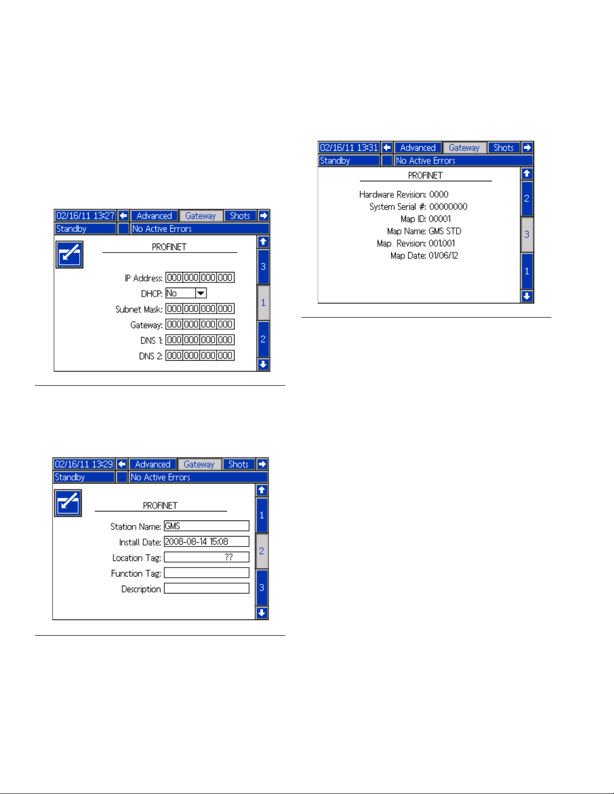
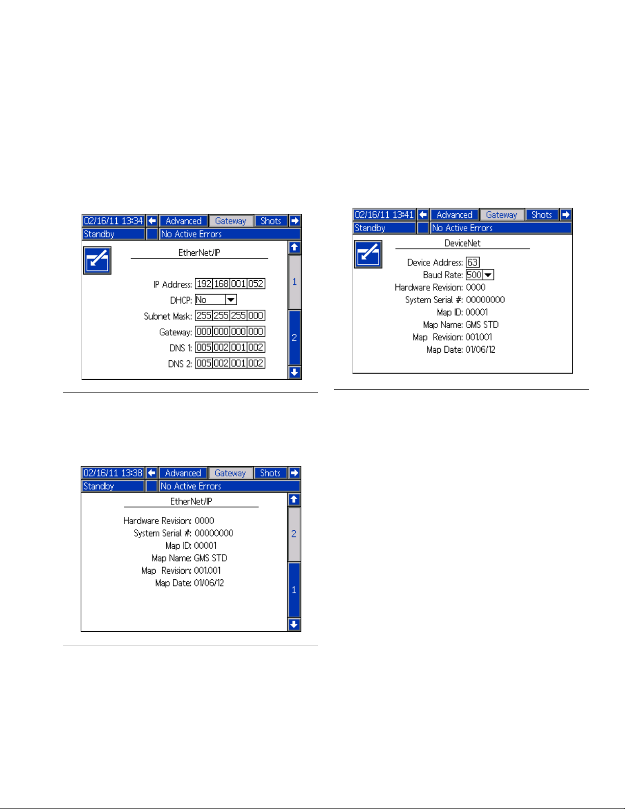
Gateway Screens . . . . . . . . . . . . . . . . . . . . . . . . 5
Available Internal Data . . . . . . . . . . . . . . . . . . . . . . 8
Automation Inputs (signals from EFR system to
PLC) . . . . . . . . . . . . . . . . . . . . . . . . . . . . . . . 9
Automation Outputs (signals from PLC to EFR
system) . . . . . . . . . . . . . . . . . . . . . . . . . . . . 11
CGM General Timing Diagrams . . . . . . . . . . . . 13
Appendix A - I/O Signal Descriptions . . . . . . . . . 22
Automation Inputs (signals from EFR system to
PLC) . . . . . . . . . . . . . . . . . . . . . . . . . . . . . . 22
Automation Outputs (signals from PLC to EFR
System) . . . . . . . . . . . . . . . . . . . . . . . . . . . 25
Appendix B - Data Exchanged . . . . . . . . . . . . . . . 27
EFR Data Exchange Elements . . . . . . . . . . . . . 28
Appendix C - Sequence Step Data Exchange . . . 36
EFR Sequence Step Data Exchange Elements 37
Appendix D - Error Number Requiring
Acknowledgment . . . . . . . . . . . . . . . . . . . . . . 38
Graco Standard Warranty . . . . . . . . . . . . . . . . . . . 42
Graco Information . . . . . . . . . . . . . . . . . . . . . . . . . 42
Related Manuals
Models
Overview
The Communications Gateway Module (CGM) provides
a control link between the Electric Fixed Ratio (EFR)
system and a selected fieldbus. This provides the
means for report monitoring and control by external
automation systems.
NOTE: Visit help.graco.com for updated EFR software,
maps, and the network configuration files listed below.
• EDS file: DeviceNet or Ethernet/IP fieldbus networks
• GSD file: PROFIBUS fieldbus networks
• GSDML: PROFINET fieldbus networks
• ACD file: DeviceNet or Ethernet/IP fieldbus networks
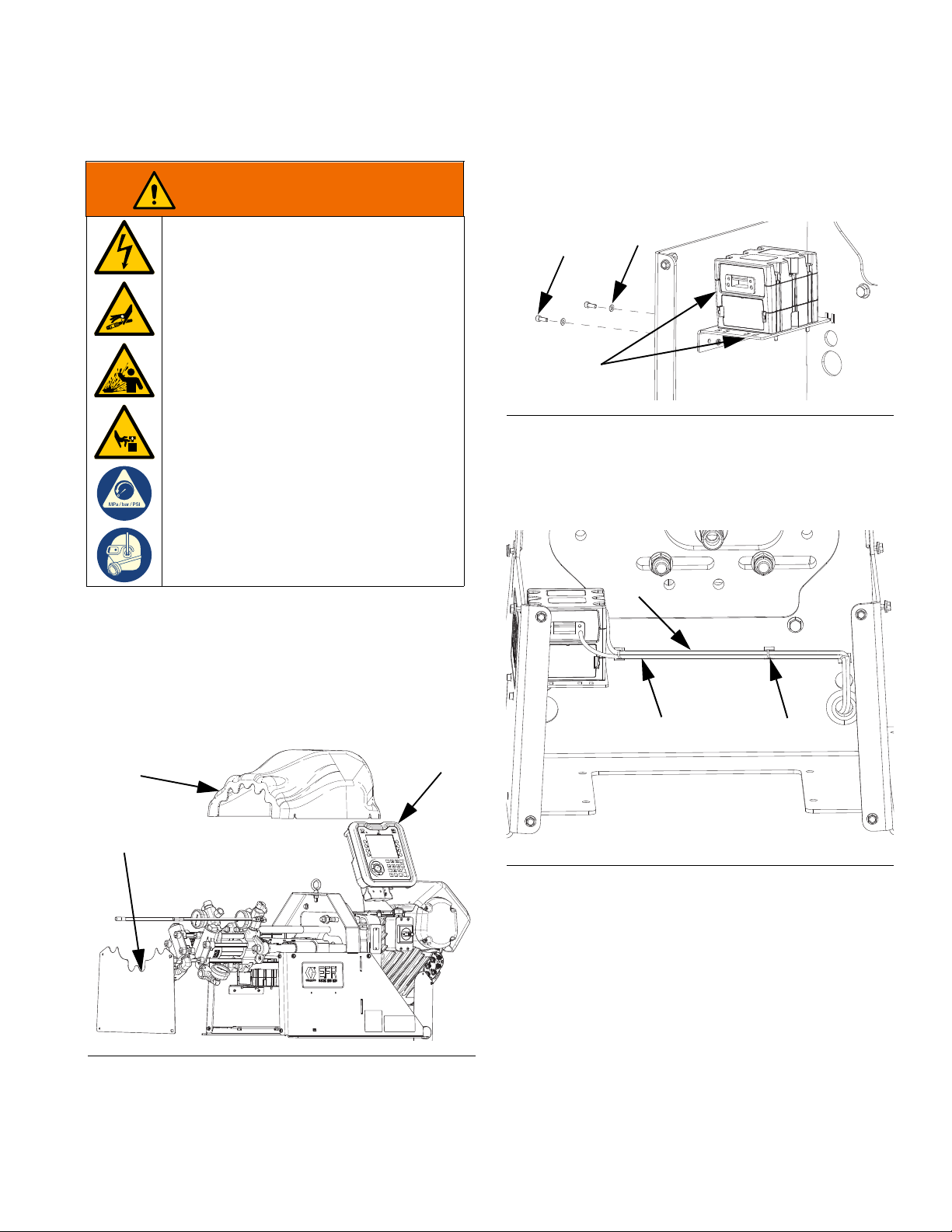
The following components are included in the CGM
Installation Kit.
CGM Software
The following software is must be installed on the CGM
module to work properly with the EFR CGM map
19A796.
• 17P796, version 3.01.004
Manual Description
312864 Communications Gateway Module, Instructions -
Parts
3A6165 Electric Fixed Ratio Proportioner, Setup -
Operation
406987 GCA CAN Cables, Reference
3A8115 Voltex
™
Dynamic Mix Valve, Instructions - Parts
Part Description
25B127 DeviceNet CGM Kit
26A700 EtherNet/IP CGM Kit
26A701 PROFIBUS CGM Kit
26A702 PROFINET CGM Kit
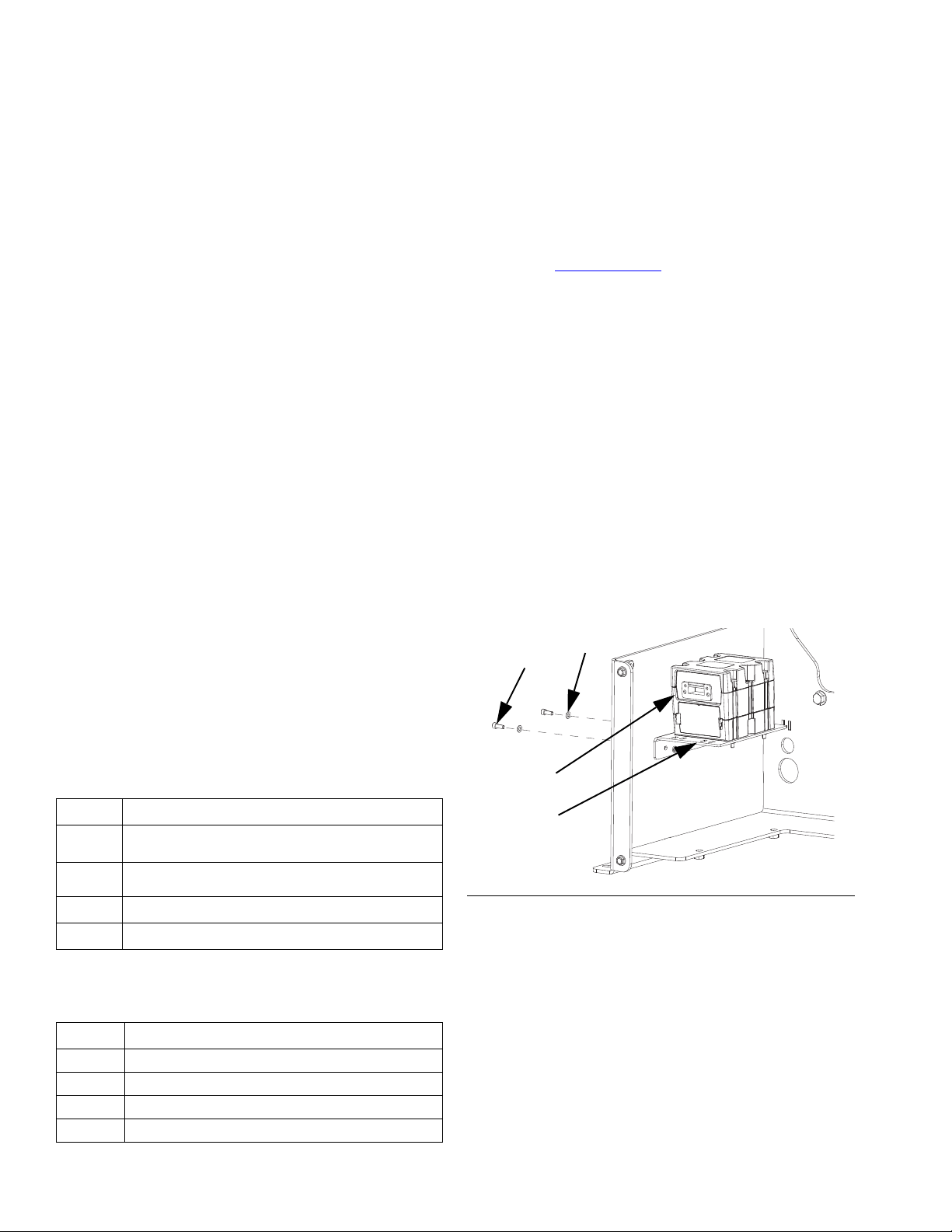
Ref. Description Qty.
ACGMKit 1
AA Gateway Module 1
AB Mounting Bracket 1
B Screw, #10-32 x .50 2
C Washer, #10, Nylon 2
D Communication Cable (not shown) 1
F
IG
. 1
BC
AA
AB

Installation
3A6338F 3
Installation
1. Ensure the system power is OFF and pressure has
been relieved. Follow the Pressure Relief Procedure
in the Electric Fixed Ratio Proportioner, Setup -
Operation manual.
2. Remove the pump yoke shroud (F) and frame cover
(G) from the EFR system.
3. Mount the CGM Kit (A) inside the system frame with
two screws (B) and washers (C).
4. Secure the CAN cable (CAN) and the fieldbus cable
(FB) to the frame using the cable ties (H) provided,
and route them through the protected opening as
shown in F
IG
. 4.
WARNING
ELECTRIC SHOCK HAZARD
To avoid electric shock, make sure the
system power is OFF before connecting or
disconnecting CAN cables.
PRESSURIZED FLUID HAZARD
This equipment stays pressurized until
pressure is manually relieved. To help
prevent serious injury from pressurized
fluid, such as skin injection, splashing fluid
and moving parts, follow Pressure Relief
Procedure when you stop spraying and
before cleaning, checking or servicing the
equipment.
PERSONAL PROTECTIVE EQUIPMENT
Wear appropriate protective equipment
when in the work area to help prevent
serious injury, including eye injury, hearing
loss, inhalation of toxic fumes, and burns.
F
IG
. 2
FE
G
F
IG
. 3
F
IG
. 4
A
BC
CAN H
FB

Installation
43A6338F
5. Connect the CAN cable from either CAN connection
on the CGM to port 1 or port 2 on the EFR.
6. If used, connect the Ethernet, DeviceNet,
PROFINET, or PROFIBUS cable (FB) to the CGM
as applicable. Connect the other end of the cable to
the fieldbus device.
7. Reinstall the pump yoke shroud (F) and the frame
cover (G) onto the EFR system.
8. Using token 19A534, perform the Install or Update
Data Map procedure in the Communications
Gateway Module, Instructions – Parts manual. See
Related Manuals on page 2.
9. Perform the Setup procedure on page 5 to
configure the fieldbus.
NOTE: To produce an accurate dispense, the dispense
valve must be controlled directly by the EFR. See the
Electric Fixed Ratio Proportioner, Setup - Operation
manual for I/O integration of the dispense valve with the
EFR.
NOTE: See Automation Outputs (signals from PLC
to EFR System) on page 25 for information on
triggering a dispense through the EFR using the CGM.
To produce accurate starts/stops, it is recommended to
use discrete I/O to trigger a dispense. See the Electric
Fixed Ration Proportioner, Setup-Operation manual for
instructions on I/O integration of the triggering signal.
NOTICE
Ensure the CAN cable is connected to an appropriate
CAN connection. Failure to connect the CAN cable
correctly can result in damage to the CGM module.
F
IG
. 5: Cable Connections
F
IG
. 6: Cable Connections
CAN
Connector 1
ti11972a
CAN
Connector 2
ti11985a

Setup
3A6338F 5
Setup
EFR and PLC Connection
Verify the PLC connection parameters are setup
correctly.
NOTE: The connection between the EFR and PLC will
not be made if the PLC connection parameters are not
set up correctly.
Gateway Screens
The Gateway screens are used to configure the
fieldbus. If the CGM is correctly installed, the Gateway
Screens will automatically be shown under the
Integration chapter of the ADM. Cycle power to the EFR
once configuration of the CGM is complete. See page 3
for installation instructions.
1. With the system on and enabled, press to
access the Setup screens.
2. Press the left arrow key once to navigate to the
main Gateway screen. See F
IG
. 7.
PROFIBUS Fieldbus Screens
These screens are shown only if a PROFIBUS Fieldbus
CGM is installed.
Screen 1
This screen enables the user to set the device address,
install date, location tag, function tag, and description.
Screen 2
This screen displays the hardware revision, system
serial number, and data map identification information.
NOTE: The map identification information should be as
follows:
Map name: EFRCGM_19A796
Map ID: 00001
Map Revision: 001, 001
Map Date: 01/24/2019
Standard Gateway Map: 19A796
Comm. Format Data-SINT
Input Assembly Instance 100
Input Byte Size 42
Output Assembly Instance 150
Output Byte Size 22
F
IG
. 7: Example Fieldbus Screen
F
IG
. 8: PROFIBUS Fieldbus Screen 1
F
IG
. 9: PROFIBUS Fieldbus Screen 2

Setup
63A6338F
PROFINET Fieldbus Screens
These screens are shown only if a PROFINET Fieldbus
CGM is installed.
Screen 1
This screen enables the user to set the IP Address,
DHCP settings, subnet mask, gateway, and DNS
information.
Screen 2
This screen enables the user to set the station name,
install date, location tag, function tag, and description.
Screen 3
This screen displays the hardware revision, system
serial number, and data map identification information.
F
IG
. 10: PROFINET Fieldbus Screen 1
F
IG
. 11: PROFINET Fieldbus Screen 2
F
IG
. 12: PROFINET Fieldbus Screen 3

Setup
3A6338F 7
EtherNet/IP Fieldbus Screens
These screens are shown only if an EtherNet/IP
Fieldbus CGM is installed.
Screen 1
This screen enables the user to set the IP address,
DHCP settings, subnet mask, gateway, and DNS
information.
Screen 2
This screen displays the hardware revision, system
serial number, and data map identification information.
DeviceNet Fieldbus Screen
This screen is shown only if a DeviceNet Fieldbus CGM
is installed.
This screen enables the user to set the device address
and baud rate, as well as view the hardware revision,
system serial number, and data map identification
information.
F
IG
. 13: EitherNet/IP Fieldbus Screen 1
F
IG
. 14: EtherNet/IP Fieldbus Screen 2
F
IG
. 15: DeviceNet Fieldbus Screen

Available Internal Data
83A6338F
Available Internal Data
See Appendix A - I/O Signal Descriptions on page 22
for additional details regarding each input/output.
Unless stated otherwise:
• In each instance, bytes are stored in little endian
order (most significant to least significant).
• PROFIBUS and PROFINET data must be mirrored
by the PLC to get the correct data out on the PLC
side. When the data is mirrored, the least significant
byte is inserted into the most significant spot, and
the most significant byte is inserted into the least
significant spot.
Example:
• Values sent through the CGM are subject to the
same maximum and minimum restrictions as those
experienced through the ADM. For example, flow
rates cannot be set to a value less than zero.
NOTE: Automation Outputs can be monitored by the
corresponding Automation Inputs to verify the EFR
received the data correctly.
Bit 15 14 13 12 11 10 9876543210
Original
Data 0011100110110111
Mirroring
Data 0111101110010011

Available Internal Data
3A6338F 9
Automation Inputs (signals from EFR system to PLC)
Instance ID Description Data Type BIT Input Byte
Index’s
1
Heartbeat To PLC Boolean 0
0
System On Boolean 1
System Ready Boolean 2
Alarms Present Boolean 3
Deviations Present Boolean 4
Advisories Present Boolean 5
Current Sequence is Playing Boolean 6
Current Sequence is Paused Boolean 7
Current Sequence is Stopped Boolean 8
1
Dispense Valve Open Boolean 9
System is Priming Boolean 10
System is Purging Boolean 11
System is Parking Boolean 12
System is Depressurizing Boolean 13
Gel Shot is Running Boolean 14
EFR is Dispensing Boolean 15
ADM Lockout is Active Boolean 16
2
Incrementing Step Time is Active Boolean 17
PLC Monitor Only is Active Boolean 18
PLC to EFR Heartbeat is Enabled and Required to
Control Boolean 19
Voltex Dynamic Mix Valve, Motor Running Boolean 20
EFR Dispense Wait Completed for Dispensing *◆Boolean 21
Voltex Dynamic Mix Valve, Motor is at Target Speed Boolean 22
Voltex Dynamic Mix Valve, Air Injection Valve Opened Boolean 23
Red Tank is Filling Boolean 24
3
Red Tank Fill Level Bit 1 Boolean 25
Red Tank Fill Level Bit 2 Boolean 26
Blue Tank is Filling Boolean 27
Blue Tank Fill Level Bit 1 Boolean 28
Blue Tank Fill Level Bit 2 Boolean 29
System is Recirculating Boolean 30
{Reserved Bits} Boolean 31
2 Current Active Sequence uint8 0-7 4
3 Current Step of the Active Sequence uint8 0-7 5
4Time Remaining to Complete Step (*or time completed
starting from 0) (XX.X s) uint16 0-7 6
8-15 7
5 Red Pump Outlet Pressure (XXXX.X bar) uint16 0-7 8
8-15 9
6 Blue Pump Outlet Pressure (XXXX.X bar) uint16 0-7 10
8-15 11
7 Red Pump Inlet Pressure (XXXX.X bar) uint16 0-7 12
8-15 13

Available Internal Data
10 3A6338F
* Refer to output bit “Step Time for Input Bytes 6 and 7
to Count Up Request.” If set, this data will increment
starting from 0 during an active dispense.
◆If start and stop are time critical, do not use the EFR
EFR Gateway Run Sequence timing diagram shown
on page 16, or the EFR Gateway Run Sequence in
Operator Mode timing diagram shown on page 17.
Instead, use the EFR Gateway Run Sequence
Operator Sequence with Voltex timing diagram
shown on page 18, and the EFR Gateway Run
Sequence with Voltex timing diagram shown on page
19 to control the sequence on the PLC. This will
ensure that the motor is up to speed when
commanding the bead to start and stop.
8 Blue Pump Inlet Pressure (XXXX.X bar) uint16 0-7 14
8-15 15
9 Pump Flow Rate (XXXX cc/min) uint16 0-7 16
8-15 17
10 Active Error Number Requiring Acknowledgment uint8 0-7 18
11 Active Operator Mode Dispense Flow Rate
(XXXX cc/min) uint16 0-7 19
8-15 20
12 Data Exchanged Element Selected uint8 0-7 21
13 Data Exchanged Element Value uint16 0-7 22
8-15 23
14 Selected Step of the Active Sequence uint8 0-7 24
15 Selected Step Amount (XXXX.XX) uint32
0-7 25
8-15 26
16-23 27
24-31 28
16 Selected Step Shot Type uint8 0-7 29
17 Selected Step Flow Rate (XXXX cc/min) uint16 0-7 30
8-15 31
18 Selected Step Calibration (XX.XX) uint16 0-7 32
8-15 33
19 Total Sequence Amount Requested (XXXX.XX cc) uint32
0-7 34
8-15 35
16-23 36
24-31 37
20 Total Sequence Amount Dispensed (XXXX.XX cc) uint32
0-7 38
8-15 39
16-23 40
24-31 41
Instance ID Description Data Type BIT Input Byte
Index’s

Available Internal Data
3A6338F 11
Automation Outputs (signals from PLC to EFR system)
Instance ID Description Data Type BIT Output Byte
Index’s
1
System Enable Request Boolean 0
0
System Shutdown Request Boolean 1
Start Current Sequence/Step, Trigger Operator
Mode Boolean 2
Pause Current Sequence Boolean 3
Stop Current Sequence Boolean 4
Priming Request Boolean 5
Purge Request Boolean 6
Parking Request Boolean 7
Depressurizing Request Boolean 8
1
*ADM Lockout Request Boolean 9
❖Increment Step Time for Input Bytes 6 and 7
Request Boolean 10
◆PLC Monitor Only Request Boolean 11
† PLC to EFR Heartbeat Enable Request Boolean 12
‡ Heartbeat to EFR Boolean 13
Voltex Dynamic Mix Valve, Motor On Request Boolean 14
Voltex Dynamic Mix Valve, Air Injection Open
Request Boolean 15
Red Tank Auto/Manual Fill Request Boolean 16
2
Blue Tank Auto/Manual Fill Request Boolean 17
Recirculation Request Boolean 18
{Reserved Bits} Boolean 19
{Reserved Bits} Boolean 20
{Reserved Bits} Boolean 21
{Reserved Bits} Boolean 22
{Reserved Bits} Boolean 23
3 Desired Active Sequence uint8 0-7 3
4 Acknowledging of the Active Error Number uint8 0-7 4
5Desired Operator Mode Dispense Flow Rate (XXXX
cc/min) uint16 0-7 5
8-15 6
6 Data Exchanged Element Desired uint8 0-7 7
7Data Exchanged Element Desired Value uint16 0-7 8
8-15 9
8 Desired Step of the Active Sequence uint8 0-7 10
9
Desired Step Amount (XXXX.XX)
uint32
0-7 11
8-15 12
16-23 13
24-31 14
10 Desired Step Shot Type uint8 0-7 15
11 Desired Step Flow Rate (XXXX cc/min) uint16 0-7 16
8-15 17
12 Desired Step Calibration (XX.XX) uint16 0-7 18
8-15 19

Available Internal Data
12 3A6338F
*If set, control of the EFR from the ADM will be
disabled.
❖If set, the “Time Remaining to Complete Step” data
from previous table will increase starting from 0.
◆If set, all requests outlined in the table above will be
ignored by the EFR system, except “Acknowledging
of the Active Error Number” and “System Shutdown
Request.”
†If set, the PLC must provide a valid “Heartbeat to
EFR” signal to the EFR to control the system. If a
valid signal is removed, the EFR system will shut
down.
‡If the “PLC to EFR Heartbeat Request” bit is set, the
PLC must provide a dynamic signal (high, then low,
then high, then low, …), changing at a maximum
time of every 10 seconds.
13 {Reserved Word} uint16 0-7 20
8-15 21
Instance ID Description Data Type BIT Output Byte
Index’s

Available Internal Data
3A6338F 13
CGM General Timing Diagrams
NOTE: A 50ms delay is suggested between each CGM signal.
NOTE: In the diagrams shown below, the ID# corresponds to the Instance ID in the Automation Inputs and Outputs
table.
When the Priming Request bit is ON, the EFR will start priming as long as the System On bit is also ON. If the
System On bit or the Priming Request bit is OFF, the EFR will stop priming.
Automation Inputs (EFR Outputs)
System On
System Ready
Alarms Present
Deviations Present
Advisories Present
System is Priming
Dispensing Valve Open
Automation Outputs (EFR Inputs)
System Enabled Request
Priming Request
EFR State
Priming Running
Key
EFR is Priming
EFR Gateway Run Smart Priming

Available Internal Data
14 3A6338F
When the Parking Request bit is ON, the EFR will start parking as long as the System On bit is also ON. If the
System On bit or the Parking Request bit is OFF, the EFR will stop parking.
Automation Inputs (EFR Outputs)
System On
System Ready
Alarms Present
Deviations Present
Advisories Present
System is Parking
Dispense Valve On
Automation Outputs (EFR Inputs)
System Enabled Request
Parking Request
EFR State
Parking Running
Key
EFR is Parking
EFR Gateway Run Park

Available Internal Data
3A6338F 15
When the Purge Request bit is ON, the EFR will start purging as long as the System On bit is also ON. If the System
On bit or the Purge Request bit is OFF, the EFR will stop purging.
The purge flow rate can be modified quickly through the data exchange.
When the Depressurizing Request bit is ON, the EFR will start depressurizing. The EFR will only stop depressurizing
if the Depressurizing Request bit if OFF.
Automation Inputs (EFR Outputs)
System On
System Ready
Alarms Present
Deviations Present
Advisories Present
System is Purge
Dispense Valve Open
Automation Outputs (EFR Inputs)
System Enable Request
Purge Request
EFR State
Purge is running
Key
EFR is Purging
EFR Gateway Run Purge
"Purge Flow Rate" can be modified, thus
allowing the Purge Flow Rate to change
on the fly
Automation Inputs (EFR Outputs)
Alarms Present
Deviations Present
Advisories Present
System is Depressurizing
Valve Signal State
Automation Outputs (EFR Inputs)
Depressurizing Request
EFR State
Depressurizing is Runing
Key
EFR is Depressurizing
EFR Gateway Run Depressurizing

Available Internal Data
16 3A6338F
If the sequence is not in operator mode, a pulse on the Start Current Sequence/Step, Trigger Operator Mode bit will
play the active sequence.
Sending the Desired Active Sequence byte is optional. If the The Desired Active Sequence byte is not sent, the
current active sequence stored in the EFR will be used.
Automation Inputs (EFR Outputs)
System On
System Ready
Alarms Present
Deviations Present
Advisories Present
Dispensed Valve Open
Automation Outputs (EFR Inputs)
Start Current Sequence/Step, Trigger Operator Mode
System Enabled Request
Desired Active Sequence
EFR State
Sequence Running
Key
EFR Sequence is running
EFR Gateway Run Sequence

Available Internal Data
3A6338F 17
If there is a step in operator mode throughout the active sequence, the EFR will only dispense that step if the Start
Current Sequence/Step, Trigger Operator Mode bit remains ON. Once the Start Current Sequence/Step, Trigger
Operator Mode bit is OFF, the EFR will continue with the active sequence.
Sending the Desired Active Sequence byte is optional. If the The Desired Active Sequence byte is not sent, the
current active sequence stored in the EFR will be used.
Automation Inputs (EFR Outputs)
System On
System Ready
Alarms Present
Deviations Present
Advisories Present
Dispensed Valve Open
Automation Outputs (EFR Inputs)
Start Current Sequence/Step, Trigger Operator Mode
System Enabled Request
Desired Active Sequence
EFR State
Sequence Running
Key
EFR Sequence is running
EFR Gateway Run Sequence in Operator Mode
"Desired Operator Mode Dispense Flow Rate" can be used to
modify flow rate on the fly during this time interval

Available Internal Data
18 3A6338F
Automation Inputs (EFR Outputs)
System On
System Ready
Alarms Present
Deviations Present
Advisories Present
Dispensed Valve Open
Voltex Dynamic Mix Valve, Motor at Speed
Automation Outputs (EFR Inputs)
Start Current Sequence/Step, Trigger Operator Mode
System Enabled Request
Desired Active Sequence
Voltex Dynamic Mix Valve, Motor On Request
EFR State
Sequence Running
Robot State
Robot Moving (If desired)
Key
EFR Sequence is running
Voltex Dynamic Mix Valve Ramp Up Time (user settable)
"Desired Operator Mode Dispense Flow Rate" can be used to
modify flow rate on the fly during this time interval
EFR Gateway Run Operator Sequence with Voltex

Available Internal Data
3A6338F 19
Automation Inputs (EFR Outputs)
System On
System Ready
Alarms Present
Deviations Present
Advisories Present
Dispensed Valve Open
Voltex Dynamic Mix Valve, Motor at Speed
Automation Outputs (EFR Inputs)
Start Current Sequence/Step, Trigger Operator Mode
System Enabled Request
Desired Active Sequence
Voltex Dynamic Mix Valve, Motor On Request
EFR State
Sequence Running
Robot State
Robot Moving (If desired)
Key
EFR Sequence is running
Voltex Dynamic Mix Valve Ramp Up Time (user settable)
EFR Gateway Run Sequence with Voltex

Available Internal Data
20 3A6338F
An ON pulse across the Stop Current Sequence bit will stop the active sequence.
Sending the Desired Active Sequence byte is optional. If the The Desired Active Sequence byte is not sent, the current
active sequence stored in the EFR will be used.
Automation Inputs (EFR Outputs)
System On
System Ready
Alarms Present
Deviations Present
Advisories Present
Dispensed Valve Open
Automation Outputs (EFR Inputs)
Start Current Sequence/Step, Trigger Operator Mode
Stop Current Sequence
System Enabled Request
Desired Active Sequence
EFR State
Sequence Running
Key
EFR Sequence is running
EFR Gateway Stop Sequence
This manual suits for next models
3
Table of contents
Other Graco Conference System manuals
Popular Conference System manuals by other brands

Cutler-Hammer
Cutler-Hammer PanelMate Series Product data

Avaya
Avaya CU-360 Installing and Administering

Altwork
Altwork TruVue Assembly and Use

Toa
Toa TS-910 Series installation manual

Philips
Philips Plena LBB 1965/00 Installation and user instructions

Rath
Rath Command Center Installation & operation manual