manuals.online logo
Brands
  1. Home
  2. •
  3. Brands
  4. •
  5. Graco
  6. •
  7. Engine
  8. •
  9. Graco 257570 User manual

Graco 257570 User manual

This manual suits for next models

2

Other Graco Engine manuals

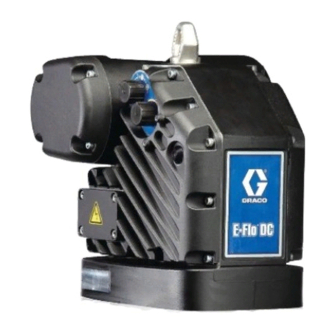
Graco E-Flo EM0011 Guide

Graco

Graco E-Flo EM0011 Guide

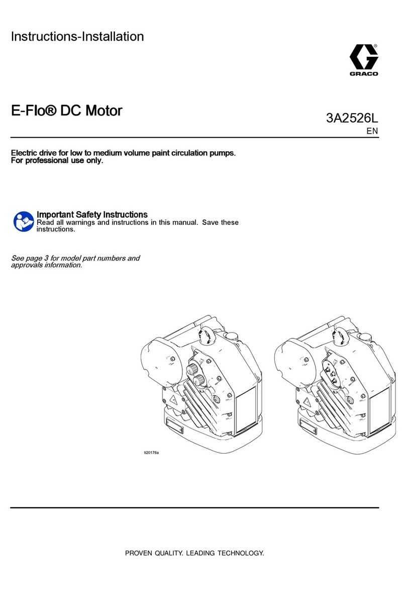
Graco E-Flo DC Series Parts list manual

Graco

Graco E-Flo DC Series Parts list manual

Graco XL 10000 Parts list manual

Graco

Graco XL 10000 Parts list manual

Graco SaniForce A Series Parts list manual

Graco

Graco SaniForce A Series Parts list manual

Graco XL 10000 User manual

Graco

Graco XL 10000 User manual

Graco Premier 222800 Operation manual

Graco

Graco Premier 222800 Operation manual

Graco 262453 User manual

Graco

Graco 262453 User manual

Graco E-Flo Service manual

Graco

Graco E-Flo Service manual

Graco Viscount I Plus Operation manual

Graco

Graco Viscount I Plus Operation manual

Graco N22DT0 Operation manual

Graco

Graco N22DT0 Operation manual

Graco Falcon C Series Operation manual

Graco

Graco Falcon C Series Operation manual

Graco Monark K Series User manual

Graco

Graco Monark K Series User manual

Graco 273199 Use and care manual

Graco

Graco 273199 Use and care manual

Graco NXT 25A641 Operating instructions

Graco

Graco NXT 25A641 Operating instructions

Graco Viscount I Plus Operation manual

Graco

Graco Viscount I Plus Operation manual

Graco 25A623 User manual

Graco

Graco 25A623 User manual

Graco President 210007 Operation manual

Graco

Graco President 210007 Operation manual

Graco GMAX 3400 User manual

Graco

Graco GMAX 3400 User manual

Graco Fast-Flo A Series User manual

Graco

Graco Fast-Flo A Series User manual

Graco EH 200 HDI User manual

Graco

Graco EH 200 HDI User manual

Graco 215-354 User manual

Graco

Graco 215-354 User manual

Graco Monark M Series Operation manual

Graco

Graco Monark M Series Operation manual

Graco 204464 B Series Operation manual
Graco

Graco 204464 B Series Operation manual

Graco E-Flo Service manual

Graco

Graco E-Flo Service manual
Popular Engine manuals by other brands

Nakanishi EM-3030T Operation manual

Nakanishi

Nakanishi EM-3030T Operation manual

Siemens COMBIMASTER CM12 operating instructions

Siemens

Siemens COMBIMASTER CM12 operating instructions

Bosch Rexroth Hagglunds CA Series Installation and maintenance manual

Bosch

Bosch Rexroth Hagglunds CA Series Installation and maintenance manual

Hyundai H170VC manual

Hyundai

Hyundai H170VC manual

MOTO GUZZI BREVA V1100 Workshop manual

MOTO GUZZI

MOTO GUZZI BREVA V1100 Workshop manual

Dualsky Track & Field Z5 instruction manual

Dualsky

Dualsky Track & Field Z5 instruction manual

Rotax 125 senior MAX evo installation manual

Rotax

Rotax 125 senior MAX evo installation manual

Kohler K361 Service manual

Kohler

Kohler K361 Service manual

MTD OHV Series user guide

MTD

MTD OHV Series user guide

Mercury D4.2L D-Tronic manual

Mercury

Mercury D4.2L D-Tronic manual

Perkins 1206E-E66TA Operation and maintenance manual

Perkins

Perkins 1206E-E66TA Operation and maintenance manual

Skov DA 174 Technical user guide

Skov

Skov DA 174 Technical user guide

Rotax 915 i A SERIES Maintenance manual

Rotax

Rotax 915 i A SERIES Maintenance manual

AL-KO PRO 350 Instructions for use

AL-KO

AL-KO PRO 350 Instructions for use

MTU 12 V 4000 Lx4 operating instructions

MTU

MTU 12 V 4000 Lx4 operating instructions

Nanni N3.30 Workshop manual

Nanni

Nanni N3.30 Workshop manual

Nanni N5.160 CR2 Operator's manual

Nanni

Nanni N5.160 CR2 Operator's manual

Robin EC13V Instructions for use

Robin

Robin EC13V Instructions for use

manuals.online logo
manuals.online logoBrands
  • About & Mission
  • Contact us
  • Privacy Policy
  • Terms and Conditions

Copyright 2025 Manuals.Online. All Rights Reserved.

- This manual contains kit installation instructions only -
Motor Kit: 257570,16F290, 16F393
Pressure Relief Procedure
Important Safety Instructions
For detailed sprayer information and warnings, see
Operation manual 313381 included with sprayer.
To help prevent injection injuries, follow this procedure
when you stop spraying and before you service or clean
the sprayer, remove parts, or repair leaks.
1. Turn power switch OFF. Unplug sprayer.
2. Turn Spray/Prime valve to PRIME to relieve pressure.
Turn pressure control knob left (counterclockwise) to
minimize pressure.
3. Trigger gun.
4. Put trigger safety in safety ON position.
NOTE: Leave Spray/Prime valve in PRIME
position until you are ready to spray again.
If you suspect that the spray tip or hose is completely
clogged or that pressure has not been fully relieved after
following the steps above, VERY SLOWLY loosen the tip
guard retaining nut or hose end coupling to relieve pressure
gradually. Then loosen it completely. Clear the tip or hose
obstruction.
313586B
Instructions
Motor Kit for Tradeworks 150™
and Tradeworks 170™Sprayers
ti10220a
ti11868a
ENG
2313586B
Motor Kit 257570, 16F290
Disassembly
1. Unplug power cord (N) and Relieve Pressure (see
page 1 or Operation manual 313381).
2. Remove 4 side shroud screws (E) (T-20 Torx).
3. Remove 4 front cover screws (B) (T-30 Torx).
4. Tradeworks 170 Only: Remove underside shroud
mounting screw (D).
5. Remove right shroud (G).
6. Remove left shroud (K).
7. Disconnect motor leads from control board (T).
8. Remove fan cover (X) by gently using a straight
blade screwdriver.
9. Remove 2 motor screws (mm) (T-20 Torx).
10. Remove motor (Q).
G
D
mm
K
T
B
Q
E
cp
ti15775a
N
X
nt
(Tradeworks 150 and 170 Series A shown)
313586B 3
Assembly
1. With motor thermal switch facing up, assemble new
motor (Q) onto pump housing (ph). Rotate fan
slightly to engage teeth. Install 2 motor screws
(mm). Torque to 20 to 25 in-lb (2.3 to 2.8 N•m).
2. Reconnect motor leads to control board (T).
3. Replace fan cover (X). Make sure clips (cp) align
with notches on motor (nt) and snap securely into
place.
NOTE: Carefully feed one lead wire through
lower-left corner opening on fan cover (X). The other
lead wire will exit between fan cover and the motor
lamination.
4. Install power cord (N) into recess on left shroud (K).
5. Reassemble both shrouds (G and K).
6. Install 4 front side screws (E) (T-20 Torx). Torque to
20 to 25 in-lb (2.3 to 2.8 N•m).
7. Install 4 front cover screws (B) (T-30 Torx). Torque to
26 to 32 in-lb (2.9 to 3.6 N•m).
8. Tradeworks 170 Only: Install underside shroud
mounting screw (D). Torque to 25 to 35 in-lb (2.8 to
3.9 N•m).
Wiring Diagram for Tradeworks 150 and 170, Series A:
WIRING DIAGRAM
WHITE
BOARD WIRE
AUTO PRIME
POWERCORD
BLACK WIRE
POWERCORD
WHITE WIRE
10A FUSE
POWERCORD
GREEN WIRE
CHASSIS
GROUND
ON/OFF
SWITCH
PRESSURE
SWITCH
ti15763a
All written and visual data contained in this document reflects the latest product information available at the time of publication.
Graco reserves the right to make changes at any time without notice.
Original instructions. This manual contains English. MM 313586
Graco Headquarters: Minneapolis
International Offices: Belgium, China, Japan, Korea
GRACO INC. P.O. BOX 1441 MINNEAPOLIS, MN 55440-1441
Copyright 2010, Graco Inc. is registered to ISO 9001
www.graco.com
Revised 09/2010
Wiring Diagram for Tradeworks 150 and 170, Series B:
GREEN
ON/OFF
SWITCH
WHITE
BLACK
PRESSURE SWITCH
BLACK
BLACK
MOTOR
ti14050a