Installation
Installation
Installation of this equipment involves potentially
hazardous procedures. Only trained and qualified
personnel who have read and who understand
the information in this manual should install this
equipment.
NOTE: To install an advanced motor, also see
Intrinsically Safe Installation Requirements for
Advanced Motors, page 12.
Fill With Oil Before Using Equipment
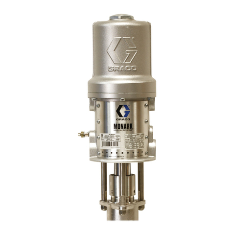
See Fig. 5. Before using the equipment, open the fill
cap (P) and add Graco Part No. 16W645 ISO 220
silicone-free synthetic gear oil. Check the oil level in
the sight glass (K). Fill until the oil level is near the
halfway point of the sight glass. The oil capacity is
approximately 1.5 quarts (1.4 liters). Do not overfill.
NOTE: Two 1 quart (0.95 liter) bottles of oil are
supplied with the equipment.
Figure 5 Sightglass and Oil Fill Cap
Power Supply Requirements
Improper wiring may cause electric shock or other
serious injury if work is not performed properly.
Have a qualified electrician perform any electrical
work. Be sure your installation complies with all
National, State and Local safety and fire codes.
See Table 1 for power supply requirements. The
system requires a dedicated circuit protected with a
circuit breaker.
Table 1 . Power Supply Specifications
Model* Voltage Phase Hz Current
EM001x 100–250
Vac
1 50/60 20 A
EM002x 200–250
Vac
1 50/60 20 A
* The last digit of the Model No. varies. See the
Models tables on pages 3–6.
Hazardous Area Cabling and Conduit
Requirements
Explosion Proof
All electrical wiring in the hazardous area must be
encased in Class I, Division I, Group D approved
explosion-proof conduit. Follow all National, State,
and Local electric codes.
A conduit seal (D) is required within 18 in. (457 mm)
of the motor for the US and Canada. See Fig. 7.
All cables must be rated at 70°C.
Flame Proof (ATEX)
Use appropriate conduit, connectors, and cable
glands rated for ATEX II 2 G. Follow all National,
State, and Local electric codes.
All cable glands and cables must be rated at 70°C.
10 3A2526D

