Gram Baker SF 1500 G Service manual

765042364 Rev.000 1
Operating- and Service manual
Baker SF 1500 G
When installing this appliance, it is of great importance to
make sure that the size of the room, where the cabinet is to
be installed, is being taken into consideration, in order to
comply with safety regulations. For further explanation
look under “Location”.

765042364 Rev.000 2
The introduction. 3
MPC 46 and the menus. 3
Temperature control, programmes and regulation: 5
User menu 8
Visual and acoustic settings 10
Settings for running cycle 11
Test program for relays and electrical components 12
Display of current sensor inputs 13
Reset the controller to factory setting 13
Parameter settings in commercial program variants – March 8th 2013 14
Plug connections onboard the controller 15
SAFETY INFORMATION 18
LOCATION 19
DEFROST WATER 21
GENERAL DESCRIPTION 22
REFRIGERANT / GWP VALUE 23
CLIMATE / TEMPERATURE CLASS 23
ELECTRICAL CONNECTION 24
DIRECTIONS FOR DAILY USE 25
STARTING UP 27
TIME CONTROLLED CHILLING (HARD CHILL) 27
TEMPERATURE CONTROLLED CHILLING (HARD CHILL) 28
TEMPERATURE CONTROLLED CHILLING (SOFT CHILL) 28
STORAGE PROGRAM 29
DEFROSTING 30
THAWING 30
DRY REFRIGERATION 31
ERROR CODES ON THE DISPLAY 31
TROUBLESHOOTING 32
DOOR MONITORING 33
LIGHT SOURCE REPLACEMENT 33
POWER FAILURE 33
CLEANING 33
LONG-TERM STORAGE 34
SERVICE 34
DISPOSAL 35
EC DECLARATION OF CONFORMITY 36
WIRING DIAGRAM 37
PIPING DIAGRAM 38

765042364 Rev.000 3
The introduction.
Since the introduction of our own standard controller I year 2001, the controller has gone through several software
updates. More program variants is developed, new functions is added to existing variants and others is been
improved.
There was a directly access to the menus on the front of our cabinet, which was a great help for the service men
and also for the workers in the factory here in Vojens.
All different settings are categorize and placed in submenus.
The access comes through main menus.
MPC 46 and the menus.
The menus are divided up in two main menus.
A menu for presentations of values in the display and settings for
alarms parameters, and another menu for technical, practical or
physical settings to a normal refrigerator or freezer.
In each main menu there exist smaller submenus.
These submenus are divided up in specific menu for kind of
cycles as defrosting or the settings for running the
evaporator fan.

765042364 Rev.000 4
Make sure the appliance is switched off at the socket before service is performed on electrical
parts. It is not sufficient to switch off the cabinet by the START/STOP key as there will still be
volta
g
e to some electrical parts of the cabinet..
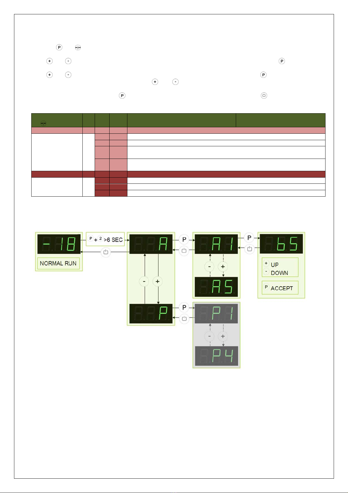
Software version and program variant in start-up sequence
When the cabinet switches ON, the controller shows the software version and program variant.
The version number glows in 2 sec. followed by name on the program variant until the controller is finished with the
start-up sequence. The program variant is like the example here below.
In the example above software ver. 2.1 and program variant M2+ is presented.
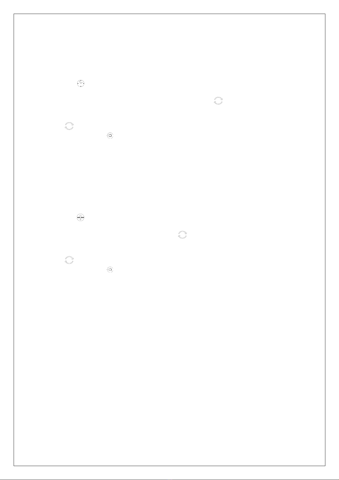
Cabinets with compressor (HAV) is given by the symbol ” ”. The
symbol should look like a “+” which means including compressor.
Cabinets without compressor (FAV) is given by the symbol ” ”.
The “-“ symbol means “Compressor not included”.
Because program variants like K and M
is difficult to present in a 7-segment
display, the symbols below is used
instead:
H (Refrigerator).
n (Extended temperature range).
P (Process cabinets).
Other program variants name:
F (freeze).
B (Counter).
V (Varm/hot/swallow cabinets)*.
E (Extreme low temperature).
* Complete new variant
Error codes in the display during normal operation
- 0 - The door is open. The alarm system is activated, if the door is not closed within a certain time.
The user is reminded that the door is not properly closed.
F1 Cabinet sensor error. In the meantime the cabinet itself will maintain the set temperature by
the memory of the controller. Service assistance is required.
F2 Evaporator sensor error.
The cabinet will keep running until the error has been mended.
Service assistance is required.
F3/F4 Condenser sensor error. The cabinet will keep running, until the error has been mended.
Service assistance is required.
Applies only to cabinets with built-in compressor.
F5 Error on the sensor for temperature controlled chilling. It has no influence on other
programmes, but it should be replaced. Service assistance is required.
F7 Indicates that the condenser temperature is too high. The cause might be a clogged
condenser, or too high ambient temperature.
If the condenser or air filter needs cleaning, the cabinet must be disconnected at the mains
power. Cleaning of the condenser is done with a brush or a vacuum cleaner.
The air filter can be removed and cleaned in a dishwasher at max. 50C.
If the ambient temperature is too high, the placement of the cabinet might be wrong, and an
alternative place should be found. Ventilation might help.
If this does not help, request service assistance.
A
pplies onl
y
to cabinets with built-in compressor.

765042364 Rev.000 5
Temperature control, programmes and regulation:
Press to see the cabinet temperature setting; the display will show the set temperature.
Temperature up:
Keep pressed. At the same time, press . Each time is pressed the temperature will change one degree.
When the display shows the desired temperature let go of the two keys and the setting has been made. By keeping
pressed, the digits change fast.
Temperature down:
Keep pressed. At the same time, press . Each time is pressed the temperature will change one degree.
When the display shows the desired temperature let go of the two keys and the setting has been made. By keeping
pressed, the digits change fast.
Automatic defrosting:
The defrosting cycle runs 4 times each day. The lamp glows to indicate that a defrosting cycle is running.
The next defrosting runs automatically 6 hours later.
Defrosting can be set from 1 to 8 times per 24 hours. See chapter "User menu".
Manual defrosting:
If the cabinet is operating under severe load (frequent door opening and frequent replenishment) manual defrosting
can become necessary.
Beside the already mentioned automatic defrosting, it is possible to perform a manual defrost cycle. Manual
defrosting is possible during each of the chilling processes, and the storage process.
If a manual defrost cycle is performed during chilling process, the chilling process continues after conclusion of the
defrosting.
The defrost cycle is started in this way:
Push the DEF button.
Thedisplayshows[dEF].ThedefrostLED indicatorflashes.
PushtheP‐buttontostartthedefrostcycle.
ThedefrostLEDindicator isturnedon.
After conclusion of the defrost cycle, the current chilling or storage process continues.

765042364 Rev.000 6
Thawing programme
Thethawingcycleisperformedbyutilizingthedefrostheater,andiscontrolledinrelationtothecabinetsensortemperature.
Thecycleendswhentheairtemperaturenolongerchanges.
Thethawingprogrammecanonlybestarted,ifthesetpointisbetween+2Cand+8C.
The thawing cycle is started in this way:
Pushthe button.
Thedisplayshows[UF].ThethawLEDindicator flashes.
PushtheP‐buttontostartthecycle.
ThethawingLEDindicator isturnedon.
After conclusion of the thawing cycle, the current storage process continues.
Dry refrigeration programme
Dry refrigeration is activated in this way:
Push the P-button and the button simultaneously for more than 3 seconds.
The display shows [dC]. The dry refrigerate LED indicator flashes.
Push the P-button to select dry refrigeration. To set dry refrigeration mode, use the +/- keys: [H0] = dry
refrigeration, [H1] = normal refrigeration.
Push the P-button to start dry refrigeration mode.
The dry refrigeration LED is turned on.

765042364 Rev.000 7
Time controlled chilling (hard chill)
This program runs by time only. Therefore, product or air temperature is disregarded. The refrigeration system runs
constantly, and the process stops when the set time has elapsed.
The process is started in this way:
Push the button.
The display shows [HCL] for 1 second. Then the set time is shown, expressed in hours and minutes.
E.g. [0.30] = 30 minutes or [1.25] = 1 hour and 25 minutes. The indicator flashes.
To set the time, use the +/- keys.
Press the P-button to save the setting, and the process starts immediately.
The indicator is turned on.
To cancel – push the button, and the cabinet is turned off. This is always possible, regardless of the
stage of the setting procedure .
If the keypad is not activated for 15 seconds, the controller returns to normal operation.
Temperature controlled chilling (hard chill)
This program runs by the temperature of a sensor placed at a warmer spot than the cabinet sensor. Therefore,
cabinet temperature or elapsed time is disregarded. The refrigeration system runs constantly, and the process
stops when the temperature setpoint is reached.
The process is started in this way:
Push the button.
The display shows [PCL] for 1 second. Then the temperature setpoint is shown.
E.g. [3] = +3C or [-15] = -15C. The indicator flashes.
To set the temperature, use the +/- keys.
Press the P-button to save the setting, and the process starts immediately.
The indicator is turned on.
To cancel – push the button, and the cabinet is turned off. This is always possible, regardless of the
stage of the setting procedure .
If the keypad is not activated for 15 seconds, the controller returns to normal operation.

765042364 Rev.000 8
Temperature controlled chilling (soft chill)
This program runs by the cabinet sensor temperature only. The surrounding air temperature of the products is
regarded. The time has no influence on the chilling process.
-10
-5
0
5
10
15
20
25
30
35
40
1 3 5 7 9 1113151719212325272931333537
Time [h]
Temperature - [°C]
Soft chill diagram
The refrigeration system runs by start/stop cycles towards the temperature setpoint for storage. The process stops
when the setpoint temperature reaches 0C, and the cabinet continues into a storage cycle.
The process is started in this way:
Push the button.
The display shows [SCL]. The indicator flashes.
Pushing the P-button starts the process. The indicator is turned on
If pushing the plus/minus buttons before pushing the P-button, the lower setpoint temperature is displayed,
as shown in the diagram above: [-8] = -8C.
To set the temperature, use the plus/minus keys.
Press the P-button to save the setting, and the process starts immediately.
The indicator is turned on.
To cancel – push the button, and the cabinet is turned off. This is always possible, regardless of the
stage of the setting procedure .
If the keypad is not activated for 15 seconds, the controller returns to normal operation.
Be aware that the lower setpoint temperature may vary according to the substance and amount of the products to
be chilled.
Display during the three chill programmes above
When one of the three programmes above are running, the display alternately shows the shortended name of the
programme, the current temperature and the set temperature or time.
Example: display during the programme “Time controlled chilling – PCL”:
[ PCL ] [ 3 ] [ PCL ] [ -15 ] [ PCL ] [ 2 ] [ PCL ] [-15 ] [ PCL ] etc.
User menu
Push on and buttons at the same time in more than 3 sec. and the first Setup menu appears in the display.
Core temp.
Surface temp.
Air temp.
Setpoint temp.

765042364 Rev.000 9
With and buttons its possible to look through each menu items in the “User menu”. Push on button to
activate the desired item and adjust the setting with and buttons.
To confirm the new setting, push button. Leave the menu item and user menu with the button.
Menu access P+
Dry refrigeration dC* Activation of dry refrigeration. [HO=off / H1=on]
Rapid thaw UF* Activation of rapid thaw. [on/off]
Local alarm setting LAL* LhL [° C] Setting the upper alarm limit. At alarm, the display shows: [ A2].
LLL [° C] Setting the lower alarm limit. At alarm, the display shows: [ A3].
Lhd [min.] Time delay for the upper alarm limit.
LLd [min.] Time delay for the lower alarm limit.
dA On/off Activation of local door alarm. At alarm, the display shows: [ A1]. [1=on / 0=off]
dAd [min.] Time delay for the door alarm.
BU On/off Activation of buzzer. The buzzer sounds at alarms [ A1], [ A2], [ A3]. [1=on /
0=off]
External alarm setting EAL* EhL [° C] Setting the upper alarm limit At alarm, the display shows: [ A4].
ELL [° C] Setting the lower alarm limit . At alarm, the display shows: [ A5].
Ehd [min.] Time delay for upper alarm.
ELd [min.] Time delay for lower alarm.
dA On/off Activation of local door alarm. At alarm, the display shows: [ A1]. [1=on / 0=off]
dAd [min.] Time delay for the door alarm.
BU On/off Activation of buzzer. The buzzer sounds at alarms [ A1], [ A4], [ A5]. [1=on /
0=off]
Sensor calibration cAL* cA [° K] Offset adjustment of A-senso
r
. Room senso
r
.
cE [° K] Offset adjustment of E-sensor. Extra sensor (placed in air or liquid container).
cF [° K] Offset adjustment of F-sensor. Sensor for low temperature protection.
ALL Activation of escorting alarm limits. [FAS]= fixed limits / [ESC] = limits following the
setpoint.
dEF Number of defrosts in 24 hours.
dPS* Selection of sensor display. Selection between: A, E or F.
*Might not be available, be available at limited or full extent, depending on programme variant and product.

765042364 Rev.000 10
Visual and acoustic settings
Push on and buttons at the same time in more than 6 sec. and the menu item [ A ] appears in the display.
With and buttons it’s possible to look through the main menu item [ A ] and [ P ]. Push on button to enter
the submenu from the main menu items.
With and buttons it’s possible to look through the submenus menu items. Push on button to enter the
desired menu item and adjust the setting with and buttons.
To confirm the new setting, push button. Leave the menu item and submenu with the button.
Menu access
P+
Alarm setup A A1 [° C] In case of condenser overheat, compressor protection cycle is started.
A2 [° C] Condenser temperature, which disconnects the compressor protection cycle.
A3 [min]. Re-enter time for acoustic alarm (min.)
A4* On/off Activation of alarm history. History only works with alarm system: LAL. [1=on /
0=off]
A5* Selection between A, E or F sensor for alarm systems LAL and EAL. Apllies to
both!
Display presentation P P1 [min.] Temperature freeze after defrosting end.
P2 [° K] Temperature freeze around setpoint. Temperature fluctuation filte
r
.
P3 [sec.] Display updating frequency.
P4 Selection of Celsius or Fahrenheit temperature scale.
*Might not be available, be available at limited or full extent, depending on programme variant and product.

765042364 Rev.000 11
Settings for running cycle
Push on and buttons at the same time in more than 6 sec. and the menu item [ C ] appears in the display.
With and buttons it’s possible to look through the main menu item [ C ], [ F ] and [ d ]. Push on button to
enter the submenu from the main menu items.
With and buttons it’s possible to look through the submenus menu items. Push on button to enter the
desired menu item and adjust the setting with and buttons.
To confirm the new setting, push button. Leave the submenu and main menu item with the button.
Menu access
P+
Compressor setup C C1 [° K] Differential for compressor cut-in and cut-out.
C2 [° C] Highest allowed temperature limit for the cabinet.
C3 [° C] Lowest allowed temperature limit for the cabinet.
C4 [min] Forced pause time for compressor between cut-out and cut-in.
C5* Number of condenser sensors connected.
C6* [min] Compressor stop by open doo
r
.
C7* [° K] Soft differential for cool/heat cut-out (kelvin)
C8* [° C] Setpoint for condenser fan
C9* [° K] Cut-out differential for condenser fan (kelvin)
Evaporator fan F F1* [° C] Temperatu
r
e allowing the evaporator fan to start afte
r
defrosting.
F2 [min.] Pause time of evaporator fan, while the compressor is stopped.
F3 [sek.] Running time of evaporator fan, while the compressor is stopped.
F4* [° K] Stop temp. of LT compressor i cascade evaporator (celcius)
Display presentation d d1 Number of defrosts / 24h
d2 [° C] Defrost stop temperature measured at the evaporator.
d3 On/off Activation of defrost by start-up sequence [1=on / 0=off].
d4* [min.] Maximum defrosting time.
d5* Selection between automatic- [1], ai
r
- [2] o
r
electric defrosting [3].
d6* [min.] Dripping time after defrosting
d7* [° C] Temperature limit deciding the defrosting method, when d5 = [1]
d8* [° C] Evaporator temperature starting an extra defrosting cycle.
d9* Defrosting after chilling (process)
*Might not be available, be available at limited or full extent, depending on programme variant and product.

765042364 Rev.000 12
Test program for relays and electrical components
Push on and buttons at the same time for more than 6 sec. and the menu item [ tC ] appears in the display.
Note: When this test program is started, all outputs are de-activated, which means the cabinet is turned off.
It might be experienced that the compressor does not start again after leaving the program, because the
compressor protection “forced pause” takes effect.
With and buttons its possible to look through each menu items in the “Service program”. Push on button to
activate the desired relay and the display glows with [ on ]. The desired relay conducts now power to the electrical
component.
Push the button to switch off the power from the electrical component. Leave the service program with the
button.
Menu access P+
P-key [on]
Compressor tC Comressor is runnin
g
, and if a condenser fan is present, it runs too.
Evaporator fan tF Evaporator fan is runnin
g
Defrost heater td Defrost heater is turned on. Warning: the heater might be very hot. Danger of
burn!
Li
g
h
t
tL Li
g
ht is switched on.
A
larm outpu
t
tA
A
ctivation of volta
g
e free contact.
A
larm output.
Display test tdP All LED’s light up for 1 sec. and the buzzer sounds. Then the software revision
number is displa
y
ed.
*Might not be available, be available at limited or full extent, depending on programme variant and product.

765042364 Rev.000 13
Display of current sensor inputs
Push on and DEF buttons at the same time in more than 6 sec. and the menu item [ P-A ] appears in the display.
With and buttons its possible to look through each menu items to check each sensor in the cabinet. Push on
button to activate the actual sensor and the display shows the actual temperature.
Leave the program with the button.
Menu access P+DEF
P-key [° C] Display message and
cause
Room sensor P-
A
Room sensor measurement is displayed F1 Room sensor error
Evaporator senso
r
P-b Evaporator sensor measurement is displayed F2 Evap.sensor erro
r
Condenser sensor 1 P-C Condenser sensor 1 measurement is displayed F3 Condenser sensor 1
error
Condenser sensor 2 P-d* Condenser sensor 1 measurement is displayed F4 Condenser sensor 2
erro
r
Extra sensor P-E* Extra sensor measurement is displayed F5 Extra sensor error
*
An overheated condenser could be caused by a clogged air filter. Can be triggered by
both C and d sensor.
F7 Overheated condenser 1
and 2
By open door this symbol is displayed. In event of a too long door opening, an alarm
is triggered [ A1].
-0- Open door symbol
Earlier Software versions
From 372 to 103: version 1.2
From 103 to 014: version 1.3
From 014 to 214: version 1.4
From 214 to 324: version 1.5
From 324 to 334: version 1.6
From 334 to 016: version 1.7
From 016 to 127: version 1.8
From 127 to 138: version 2.0
From 138 to 122: version 2.1
From 122: version 3.0
Reset the controller to factory setting
To reset the controller to factory settings:
Push + + for more than 6 seconds. The display shows "rES".
Push , and a beep sounds for confirmation.

765042364 Rev.000 14
Parameter settings in commercial program variants – March 8th 2013
Refrigerator Extended refrigerator Freezer
K1+ B1+ K7+ M1+ M2+ M3+ B2+ F1+ F2+ P1+ F4+ B3+
Systemvars Version number 85.75 85.75 85.75 85.75 85.75 85.75 85.75 85.75 85.75 85.75 85.75 85.75
Setpoint (celsius)
5555455-18-18-18-18-18
Temperature range (celcius)
+12/+2 +12/+2 +12/+2 +12/-5 +12/-5 +12/-5 +12/-5 -5/-25 -5/-25 +10/-30 +10/-25 -5/-25
Menu access: P+1
Dry ref rigeration on=H0/off=HI
dC -----HI---HIHI-
Thaw ing on/off
UF -----oFF---oFFoFF-
Local Alarm Limits LAL
Upper local alarm limit (celcius)
LHL 25 25 25 25 8 25 25 25 25 25 25 25
Low er local alar m limit (celcius)
LLL------------
Time delay f or upper alarm limit (min.)
LHd 606060606060606060606060
Tiem delay f or low er alarm limit (min.)
LLd------------
Door alarm on=1/off =0
dA 111111111111
Time delay f or open door (min.)
dAd 555515555555
Buzzer for local alarm on=1/off =0
BU 111111111111
External Alarm Limits EAL
Upper external alarm limit (celcius)
EHL 25 25 25 25 8 25 25 25 25 25 25 25
Low er external alarm limit (celcius)
ELL -35 -35 -35 -35 0 -35 -35 -35 -35 -35 -35 -35
Time delay f or upper alarm limit (min.)
EHd 60 60 60 60 10 60 60 60 60 60 60 60
Time delay f or low er alarm limit (min.)
ELd 60 60 60 60 60 60 60 60 60 60 60 60
Door alarm on=1/off =0
dA------------
Time delay f or open door (min.)
dAd------------
Buzzer for local alarm on=1/off =0
BU------------
Calibration of sensor cAL
Offset adjustment sensor A (kelvin)
cA 000000000000
Offset adjustment sensor E (kelvin)
cE --------- 0--
Offset adjustment sensor F (kelvin)
cF ------------
Frost Protection FP
Activation of frost protection On=1/Of f=0
Act------------
Test of f rost protection
tES ------------
Setpoint of f rost protection (celcius)
SEt ------------
Display of current sensor temperaturer (celcius)
PrE ------------
Fixed or escorting alarm limits (FAS - ESC)
ALL FAS FAS FAS FAS FAS FAS FAS FAS FAS FAS FAS FAS
Sof t chilling (sof t-chill)
SCL --------- -8--
Hard chilling (hard-chill)
HCL ---------3.00--
Time controlled chilling (timed-chill)
PCL --------- -18--
Number of defrosts / 24h
444444444444
Selected sensor display
dPS ------------
Alarm & presentation
Alarm settings
A
Condenser monitoring alarm on (celcius)
A1 65 65 65 65 65 65 65 65 65 65 65 65
Condenser monitoring alarm off (celcius)
A2 40 40 40 40 40 40 40 40 40 40 40 40
Genindtrædelses tiden for akustisk alarm (min.)
A3 555555555555
Alarm history on=1/off =0
A4------------
Selection of sensor for alarm system
A5------------
Mulige valg af følere til alarm system
------------
Præsentation af temperatu
r
P
Temperature display hold after defrost
P1 30 30 30 30 30 30 30 30 30 30 30 30
Temperature display hold during normal operation
P2 333333333333
Display updating frequency (sec)
P3 10 10 10 10 10 10 10 10 10 10 10 10
Temperature display, Celsius or Fahrenheit
P4 CCCCCCCCCCCC
System setup
Compressor settings C
Diff erential f or compressor start and stop (kelvin)
C1 555545555555
Max. allow ed setpoint (celcius)
C2 12 12 12 12 12 12 12 -5 -5 10 10 -5
Min. allow ed setpoint (celcius)
C3 2 2 2-5-5-5-5-25-25-30-25-25
Compulsory compressor pause time (min.)
C4 555555555555
No. of sensors f or condenser monitoring
C5 111121112111
Door open time before compressor stops (min.)
C6 111111111111
Soft differential for cool/heat cut-out (kelvin)
C7------------
Setpoint for condenser f an
C8- 35---- 35---- 35
Cut-out differential for condenser fan (kelvin)
C9- 5---- 5---- 5
Evapora tor fan settings F
Evap.fan start after defrost, and during dry refrig. (celcius)
F1 - -1 - -1 -1 -3 -1 -1 -1 -1 -1 -1
Evap.fan pause time at compressor stop (min.)
F2 505555055550
Ford. vent. køretid ved kompressor stop (sek.)
F3 60 60 60 60 60 60 60 60 60 60 60 60
Stop temp. of LT kompressor ic cascade evaporator (celcius)
F4 ------------
Defrost settings d
Number of defrosts / 24h
d1 444444444444
Stop temperature in evaporator during defrost (celcius)
d2 7474744441244
Defrosting on/off = (0/1) at pow er up first time
d3 000000000000
Max allow ed defrosting time (min.)
d4 30 30 30 30 30 30 30 30 30 30 30 30
Def rosting mode (1=automatic, 2=air, 3=electrical)
d5 232131333333
Drip time after defrost stop (min.)
d6 040404444244
Limit for automatic defrosting mode (celcius)
d7 222424244444
Evaporator monitoring (celcius)
d8 -35 -35 -35 -35 -35 -35 -35 -35 -35 -40 -35 -35
Defros t af ter chilling stop
d9 --------- 1--

765042364 Rev.000 15
Plug connections onboard the controller
The description here below explains the plugs or terminals to each special function and relay.
Plu
g
Electrical component Description
1 230 Volt relay – K1 The relay supplies the compressor and the condenser fan with
power.
2
3
4
5 230 Volt relay – K3 The relay supplies the evaporator fan with power.
6
7 230 Volt relay – K2 The relay supplies the defrosting heating element and the drip
water heating element with power
8
14
15
9 230 Volt relay – K4 The relay supplies the halogen light transformer with power
(
230V/12V
)
.
10 230 Volt relay – K7 and K8 The relay supplies the front frame heater, re-evaporating
heating element, and the condensing pump with power. When
the cabinet is switched on, the power is constantly viable.
11
12
13
17
18 Plug connection for the safety
thermosta
t
The plug is connected in series with the defrosting heating
element.
19 230 Volt relay – K5 The potential free alarm relay.
The relay changes position when the cabinet switches the
power on. By alarms and by power failure the relay switches
back to normal position.
16 230 Volt input These terminals are the power input connection with 230 V to
the controller.
20 Digital input from the door contact When these terminals are not in use, the controller lets the
evaporator fans keep running. By shortcutting the terminals, the
fan stops.
21

765042364 Rev.000 16
A
Room sensor input NTC sensor
B Evaporator sensor input NTC sensor
C Condenser sensor input 1 NTC sensor
D Condenser sensor input 2 NTC sensor
E Sensor input for a extra sensor NTC sensor

765042364 Rev.000 17
Thank you for choosing a quality product from Gram Commercial.
This manual will advise you how to install, use and maintain your new product.
Before our products leave the factory, they undergo a full function and quality test.
Should you nevertheless experience problems with the product, then contact your local dealer. Gram Commercial
representatives and dealers placed all over the world are ready to help you.
Please refer to your dealer for information about the warranty coverage of your new Gram product.
Any warranty is subject to correct use according to specifications in this user manual, where e.g. common
maintenance and eventual repairs are carried out by authorized technicians with proper knowledge of the product
and only using original spare parts.
Changes in installation and other use of the product than prescribed in this manual, might affect the operation and
durability of the product.
The manual is written according to our current technical knowledge. We constantly work on updating this
information, and we reserve the right to make technical changes.
Application
This product is designed for chilling or freezing of bakery products.
The product is only to be used for the purpose for which it has been expressly designed. Any other use could cause
that the products stored in the appliance are not kept at the right temperature.
The product is not suited for storing blood plasma, laboratory samples, pharmaceuticals or similar substances. The
manufacturer will not be held liable or responsible for any damage caused by improper, incorrect or unreasonable
use of the product.

765042364 Rev.000 18
Safety information
Important
Description of symbols used in this manual.
Warning
Lacking observation to these instrucions might result in accidents with personal injury.
Important If these instructions are not observed, the product might be damaged or destroyed.
Be aware that Gram Commercial has taken precautions to ensure that the safety of the product is in order.
Please read carefully the following information regarding safety.
It is important that everyone who is in connection with, must install, or use the product to have the
necessary information and access to this manual.
This product is not intended for use by persons with reduced physical, sensory or mental capabilities,
or lack of experience and knowledge, unless they have been given supervison or instruction
concerning use of the product by a person responsible for their safety. Children should be
supervised to ensure that the
y
do not pla
y
with the product.
The product might contain parts with sharp edges in the compressor compartment, and in the inside
compartment.
The product is not to be transported on a sack truck, there is a danger of loosing the balance,
causing danger to persons.
Prior to locking the cabinet door, it is crucial to inspect the inside of the cabinet in order to prevent
confinement of persons.
Do not store explosive substances such as aerosol cans with a flammable propellant in the product.
Do not use electrical appliances inside the food storage compartment of the product.
Do not pull the power cord to dicconnect the product, or when moving the product.
Correct set up gives the most effective operation.
The product should be located in a dry and adequately ventilated room.
To ensure efficient operation, it may not be placed in direct sunlight or against heat-emitting
surfaces. The product is designed to operate in an ambient temperature between +16C and +40°C.
Avoid placement of the product in a chlorine/acid-containing environment (swimming bath etc.) due
to risk of corrosion.
The product and parts of the interior is equipped with a protecting film, which should be removed
before use.
Clean the product with a mild soap solution before use.

765042364 Rev.000 19
Location
When receiving the cabinet, check the packaging material for damage.
If any damage occurs at the packaging material, it should be considered if the cabinet might have been damaged
too. If the damage is substantial, please contact your dealer.
If the damage on the packaging material is only minor, remove the packaging material and examine the cabinet for
any damage.
The set up place must be level and horizontal.
To remove the transport pallet, the cabinet must be layed down on its back.
The heaviest part of the cabinet is at the top. Be very careful when tilting and laying down the
cabinet, the weight is far over 100 kg at the top. This task requires at least 2 persons.
When the cabinet is placed on its back, the transport pallet can be removed by loosening the 5 screws that fastens
the pallet to the bottom of the cabinet.
Now the cabinet can be raised again, and moved to its place.

765042364 Rev.000 20
This appliance shall be installed in a room with a floor area not less than the
marked minimum room floor area shown with a numeric value where the A is
on the pictogram to the left of this text.
An example:
If the text below the square is: ≥ 11 m2 – It does mean that the room in which
the appliance is to placed must have a floor surface area of at least 11 m2.
The label indicating this minimum floor area size is positioned next to the
name plate.
When installing / building in this product, it is imperative to ensure proper ventilation around the
cabinet. In order to do so, the following demands must be met.
Minimum free height above the cabinet 500 mm
Minimum free space behind the cabinet 50 mm (distance created by the two distance
pieces mounted on the back of the cabinet)
Do not obstruct any ventilation openings in the appliance enclosure or in the structure
for building in.
Because of the heavy weight of the product, the floor might be damaged or scratched when moving
the product.
If the product has been transported in horizontal position it must stand upright at least 2 hours
before it is started to allow the oil from the compressor to run back.
Correct set up gives the most effective operation.
The product should be located in a dry and adequately ventilated room.
Table of contents
Other Gram Refrigerator manuals

Gram
Gram KS 32215-63 User manual

Gram
Gram KF 6376-90 FN User manual

Gram
Gram KF Type I User manual

Gram
Gram KF 32255-63/1 User manual

Gram
Gram KF 471851 N User manual

Gram
Gram KF 130-11 M56 Series User manual

Gram
Gram KS 150 User manual

Gram
Gram KSU 3136-50 /1 User manual

Gram
Gram KS290 User manual

Gram
Gram KS 42476-60/1 User manual

Gram
Gram KS 32315-63/1 User manual

Gram
Gram KS 3315-93 X/1 User manual

Gram
Gram KS 3315-90 F User manual

Gram
Gram KS 3265-90 User manual

Gram
Gram LC 494186 F X User manual

Gram
Gram KFI 301251 User manual

Gram
Gram KS 3215-90 User manual

Gram
Gram KF 411864 N X User manual

Gram
Gram KF 3255-94 User manual

Gram
Gram Standard Plus Service manual