Gram ECO PLUS User manual

765042196 Rev. 000 1
GRAM ECO CO2 REMOTE
User manual
ECO PLUS, ECO TWIN, ECO EURO, ECO MIDI

765042196 Rev. 000 2
Gram Commercial A/S
Aage Grams Vej 1
6500 Vojens
+45 73 20 12 00
www.gram-commercial.com

765042196 Rev. 000 3
Contents
Application .................................................................................................................. 4
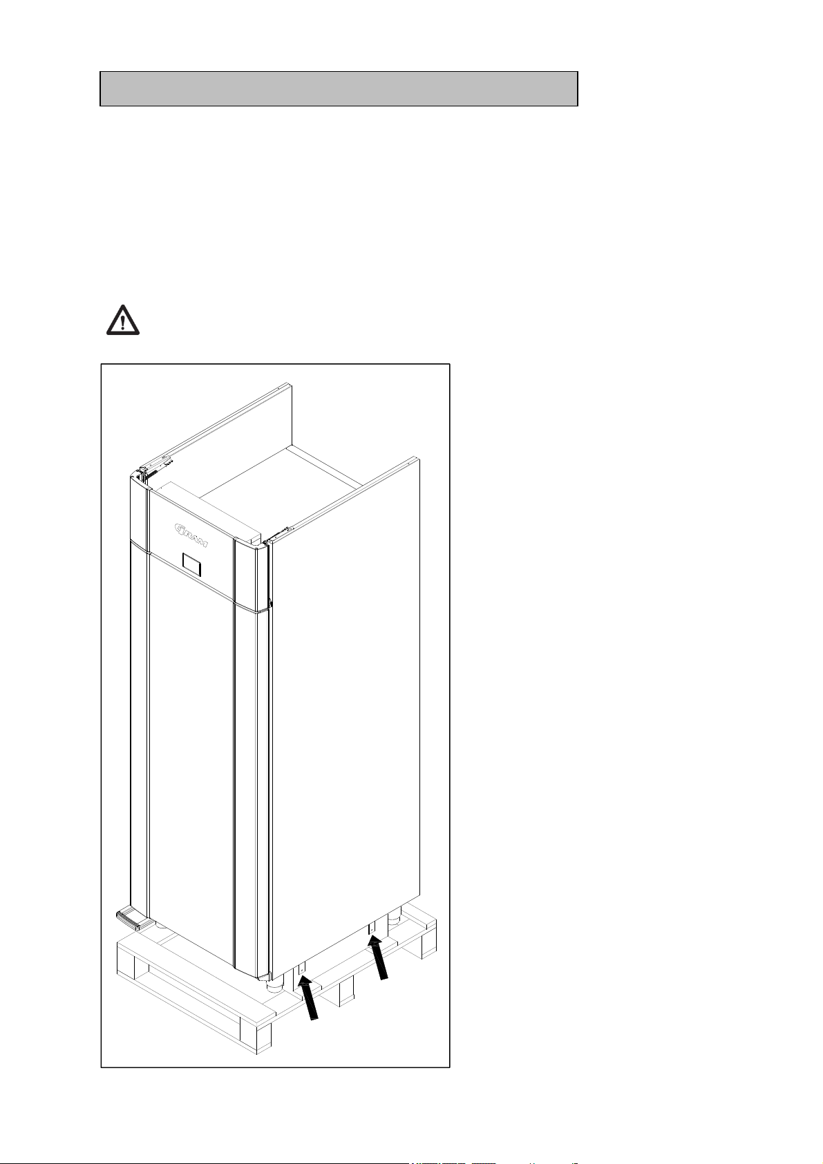
Safety information ...................................................................................................... 5
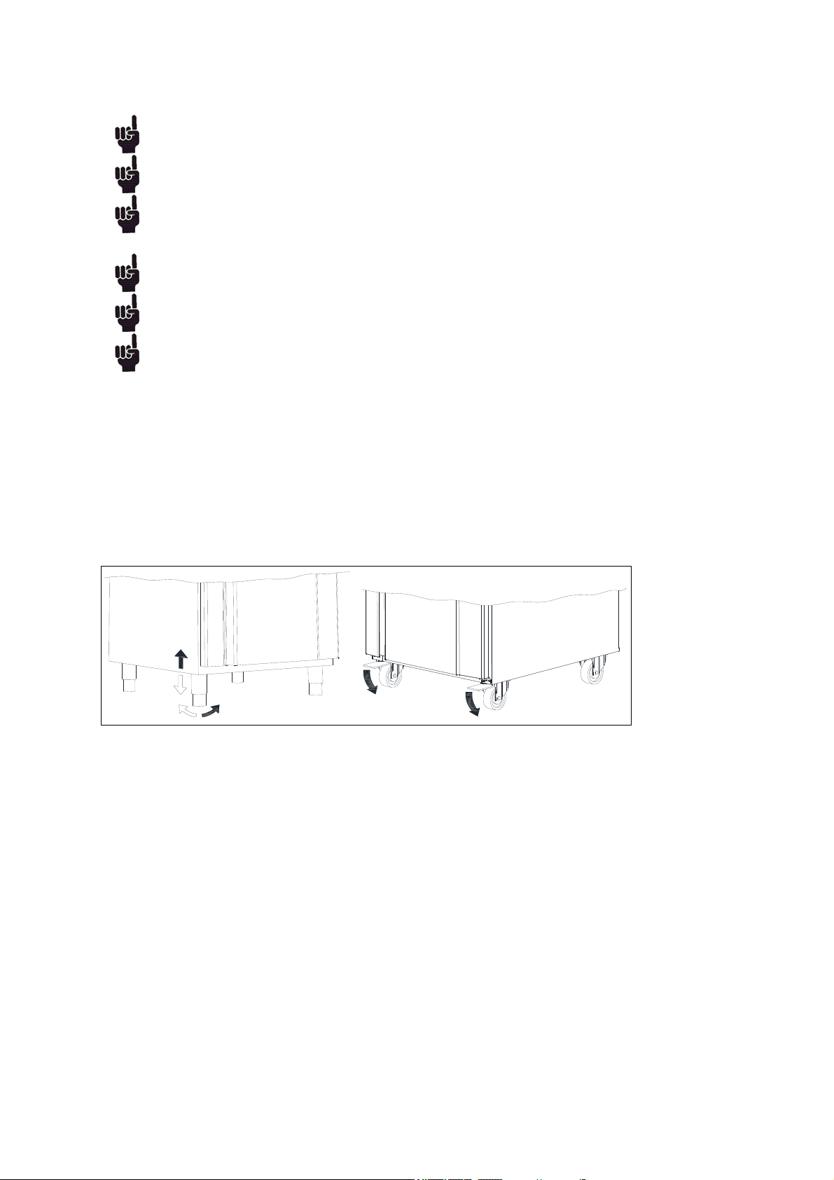
Location ...................................................................................................................... 6
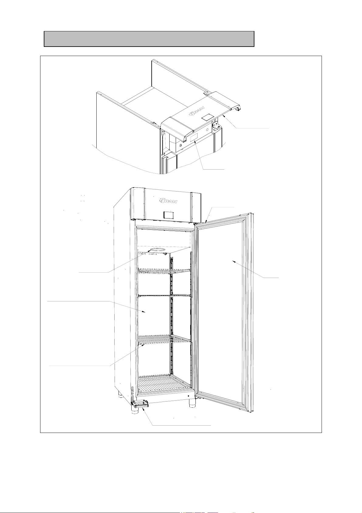
General description .................................................................................................... 9
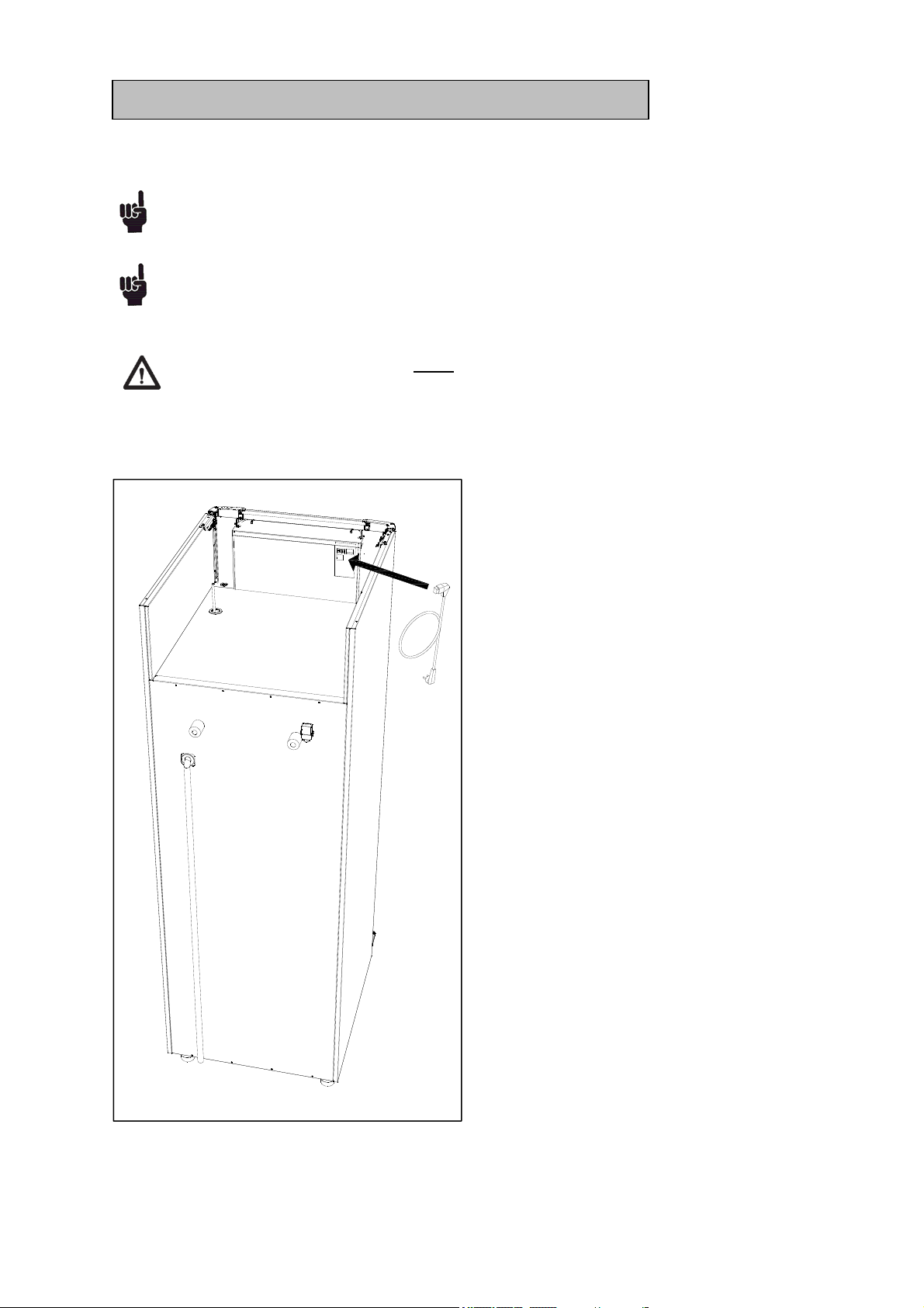
Electrical connection ................................................................................................ 10
General use .............................................................................................................. 11
Operating the product (Danfoss Controller AKCC 550A) ......................................... 13
Errors and alarms...........................................................................................................................16
User menu.......................................................................................................................................16
Operating the product (Carel MPXpro controller) ..................................................... 17
Errors and alarms...........................................................................................................................23
User menu.......................................................................................................................................24
Operating the product (no controller) ........................................................................ 24
Troubleshooting ....................................................................................................... 24
Defrost water ............................................................................................................ 25
Door closing mechanism .......................................................................................... 25
Power failure ............................................................................................................ 26
Cleaning ................................................................................................................... 26
Door gaskets ............................................................................................................ 26
Long term storage .................................................................................................... 26
Service ..................................................................................................................... 27
Disposal ................................................................................................................... 28
Declaration of incorporation of partly completed machinery ..................................... 29
Wiring diagram Danfoss AKCC 550A ....................................................................... 30
Wiring diagram Carel MPXpro .................................................................................. 37
Wiring diagram - no controller .................................................................................. 44
Piping diagram ......................................................................................................... 51

765042196 Rev. 000 4
ENGLISH
Thank you for choosing a quality product from Gram Commercial.
This manual will advise you how to install, use and maintain your new product.
Before our products leave the factory, they undergo a full function and quality test.
Should you nevertheless experience problems with the product, then contact your
local dealer.
Gram Commercial subsidiaries and dealers placed all over the world are ready to
help you.
Products produced by Gram Commercial are covered by different warranty terms
related to the country in which the product is sold.
This warranty is subject to correct use according to specifications, where e.g.
common maintenance and eventual repairs are carried out by technicians appointed
by the dealer and with a general knowledge of the product.
Changes in installation and other use of the product than specified in this manual,
might affect the operation and durability of the product.
The manual is written according to our current technical knowledge. We constantly
work on updating this information, and we reserve the right to make technical
changes.
Application
This product is designed for storage of foodstuff at a constant temperature. The
product may not be used for chilling or freezing of foodstuff.
The product is only to be used for the purpose for which it has been expressly
designed. Any other use could cause that the products stored in the product are not
kept at the right temperature.
The manufacturer will not be held liable or responsible for any damage caused by
improper, incorrect or unreasonable use.

765042196 Rev. 000 5
Safety information
Important
Description of symbols used in this manual.
Warning
Lacking observation to these instructions might result in accidents with
personal in
j
ur
y
.
Important If these instructions are not observed, the product might be damaged or
destroyed.
Be aware that Gram Commercial has taken precautions to ensure that the safety of
the product is in order.
Please read carefully the following information regarding safety.
It is important, that everyone who are to use or install the product, to have access to
this manual.
This appliance is not intended for use by persons with reduced physical, sensory or
mental capabilities, or lack of experience and knowledge, unless they have been
given supervision or instruction concerning use of the appliance by a person
responsible for their safet
y
.
Children should be supervised to ensure that they do not play with the appliance.
The appliance might contain parts with sharp edges in the compressor
compartment, and in the inside compartment.
The appliance is not to be transported on a sack truck, there is a danger of losing
the balance, causin
g
dan
g
er to persons.
Do not pull the power cord to disconnect the appliance, or when moving the
appliance.

765042196 Rev. 000 6
Location
When receiving the product, check the packaging material for damage.
If any damage occurs at the packaging material, it should be considered if the
product might have been damaged too. If the damage is substantial, please contact
your dealer.
The transport pallet can be removed by loosening the screws that fasten the pallet to
the product.
This task requires at least 2 persons. The heaviest part of the product is at the top.
Be aware of this, when removin
g
the transport pallet.
Fig.1

765042196 Rev. 000 7
Because of the heavy weight of the product, the floor might be damaged or
scratched when moving the product.
Correct set up gives the most effective operation.
The product should be located in a dry and adequately ventilated room.
To ensure efficient operation, it may not be placed in direct sunlight or against
heat-emitting surfaces. The product is designed to operate in an ambient
temperature between +16C and +40°C.
Avoid placement of the product in a chlorine/acid-containing environment
(swimming bath etc.) due to risk of corrosion.
The product and parts of the interior is equipped with a protecting film, which
should be removed before use.
Clean the product with a mild soap solution before use.
The set up place must be level and horizontal.
For versions with legs, use the adjustable legs to make sure that the product stands
level and upright.
For versions with castors, the locking devices of the two front castors must be
activated, when the product is in place. The base must be level, and the product may
not be placed on frames or the like.
Fig. 2

765042196 Rev. 000 8
There must always be 20 cm of free space above the product, to allow for service.
The product should be placed as close as possible up against the wall.
Fig. 3

765042196 Rev. 000 9
General description
Fig. 4
Front panel
Display
Door
Gasket
Air intake
Air distribution plate
Shelves for storage
Pedal door opener

765042196 Rev. 000 10
Electrical connection
Read the text below thoroughly before electrical connection.
The product is intended for connection to alternating current. The connection
voltage (V) and frequency (Hz) are shown on the name plate in the cabinet (see
Fi
g
. 8
)
. Onl
y
the supplied cord is to be used.
Never use an extension cord for this appliance!
If a wall socket is placed in a longer distance than the length of the supplied power
cord, contact an electrician to establish a wall socket within the range of the
supplied power cord.
If the product is defective, it must be examined by a skilled service technician
knowing the installed controller and experienced in servicing a CO2 cabinet.
In general, it must be examined by the company who has connected the product.
Fig. 5

765042196 Rev. 000 11
Always disconnect the power if interruptions in power supply occur, and when
electrical parts are removed/put on, and before cleaning and maintenance of the
product.
Do not use the product before all coverings are installed, so that live or rotating
machine parts cannot be touched.
The product is not to be used outdoor.
All earthing requirements stipulated by the local electricity authorities must be
observed. The plug and wall socket should then give correct earthing. If necessary,
contact an electrician.
Make sure the product is switched off at the socket or that the kettle plug
is disconnected, before service is performed on electrical parts. It is not
sufficient to switch off the product at the controller.
General use
Do not damage the refrigeration system parts.
If the product is fitted with a re-evaporation tray underneath the cabinet it is
important not to service/clean the tray or the heater, before the cabinet has been
turned off long enough to make sure that the re-evaporaton heater has cooled
off, in order to prevent the risk of burns.
Do not use electrical devices inside the product.
To ensure correct and efficient air flow in the cabinet, the shaded areas must be
kept free of items. (see Fig. 6)
All items to be stored, that are not wrapped or packed, must be covered in order
to avoid unnecessary corrosion of the inner parts of the cabinet.
If any controller parameters are changed from default, this could cause that the
product is not functioning normally, and harmful temperatures could damage
items that are kept inside the product.
Maximum loading of wire shelf: 40 kg
Do not store explosive substances such as aerosol cans with flammable
propellant in this appliance.

765042196 Rev. 000 12
Fig. 6
Do not place any products below the bottom shelf support or above the upper
load line marking

765042196 Rev. 000 13
Operating the product (Danfoss Controller
AKCC 550A)
Starting up:
Plug in the appliance.
Make sure that the 2 - pole main switch is turned on.
The display part is placed behind the top panel and can be accessed by opening the
top panel.
Display explanation:
The above shown display part has a three digit read-out.
On the left side of the read out, three LEDs are placed. These three LEDs have the
following purpose.
= Cooling on (when this LED is lid, the cooling is on)
= Defrost on (when this LED is lid, a defrost cycle is ongoing)
= Inside fan running (when this LED is lid, the internal fan is on)
If all three LEDs are flashing, this is an indication for an ongoing alarm or error.
The 3 buttons placed on the right side of the display read-out, are used to access and
adjust different parameters.
Buttons:
The upper button:
if pushed shortly during normal operation the controller will cancel and display
any error(s) occurring. If more than one alarm does occur, use the uppermost
or lowermost button to scan the different alarms.
if pushed and kept pushed during normal operation until the display shows r01
the main parameters of the controller are accessed. This is only used by the
end-user when switching the controller on and off.
If pushed being in a set menu (either change of a setting or moving from one
parameter to another the value will be increased)

765042196 Rev. 000 14
The center button: (Adjusting the cabinet temperature set point)
if pushed and kept pushed during normal operation until the display starts
flashing, the cabinet temperature set-point can be adjusted using the upper and
lower button.
If pushed after changing a value the controller does save the new value and
return to the previous level.
The lower button:
if pushed shortly during normal operation the controller will display the actual
temperature of the evaporator probe.
if pushed and kept pushed for more than 4 seconds, during normal operation,
an ongoing defrost cycle will be canceled or a manual defrost cycle will be
started.
If pushed being in a set menu (either change of a setting or moving from one
parameter to another the value will be decreased)
As end-user it is only possible to make the following adjustments:
Adjusting the cabinet temperature set point (as explained above)
Turning the cabinet controller on/off
Switching the internal light (Only on MIDI KG/FG products)
Turning the cabinet on/off
As default setting the cabinet controller is delivered turned off.
This means that the display will show oFF, when power supply is connected.
Please also check that the main switch, placed on the control box is turned on.
The following is done in order turn the controller on. The same approach is used
when turning the controller off (Setting r12 to 0).
Push the upper button and keep it pushed during normal operation until the
display does show r01.
Push the upper or the lower button until r12 is displayed.
Push the center button.
Push the lower or the upper button in order to switch between the settings 0
and 1 (-1 is only for service).
o Setting 0 means the cabinet is OFF.
o Setting 1 means the cabinet is ON.
Confirm the new setting by pushing the center button.
In order to skip the r01 parameter, the controller does only need to be left
untouched for approx. 30 seconds. This will make the controller fall back to the
normal operation mode, meaning that the cabinet will either be in oFF – mode
or be running.

765042196 Rev. 000 15
Cabinet light
On all cabinets, besides the MIDI glass door cabinets with internal light, the cabinet
light is placed on the cabinet outside, above the door. This light is operated by the
main controller which means that the way it works cannot be changed.
When the cabinet door is opened the light above the door is turned on. When closing
the door again, the cabinet light above the door will remain on for two minutes.
These two minutes are a main function in the Danfoss controller which cannot be
adjusted. Two minutes after closing the door the light will switch off.
Switching the internal light (Only on MIDI KG/FG products)
On Midi glass door cabinets the cabinet LED strips are placed inside the cabinet
storage room. The light can be operated in two different ways:
1. When the cabinet door is opened the light above the door is turned on. When
closing the door again, the cabinet light above the door will remain on for two
minutes. These two minutes are a main function in the Danfoss controller
which cannot be adjusted. Two minutes after closing the door the light will
switch off.
2. By switching the light main switch in the left front of the top control box,
placed behind the top panel, to the position showing a light bulb, the internal
light will be turned on constantly.

765042196 Rev. 000 16
Errors and alarms
User menu
User menu overview:
For information on user menu please see manual over the selected CO2 controller

765042196 Rev. 000 17
Operating the product (Carel MPXpro controller)
Starting up
Plug in the appliance
Default setting of the cabinet controller is that it is delivered turned on.
This means that the controller will start regulating, when power supply is connected,
and the main switch is in the on position.
Turning the cabinet on/off
To turn the cabinet on/off the 2-pole main switch, on the left side of the main control
box, placed in “the compressor compartment” is used.
The display
The display, used for adjusting settings and displaying temperature or alarm codes, is
placed behind the top panel and can be accessed by opening the top panel.
Display layout/explanation:
The above shown display has a three-digit read-out.
Within the read-out area, several LEDs are placed. These LEDs give the following
indications.
In general = When a LED is flashing the activation is delayed or limited.
= Cooling on (when this LED is lit, cooling is on)
= Inside fan running (when this LED is lit, the internal/evaporator fan is on)
= Defrost on (when this LED is lit, a defrost cycle is ongoing)
= If the LED is flashing, this is an indication for the door being open or an
ongoing alarm or error.
HACCP = When this LED is lit, a HACCP alarm is ongoing. When this LED is flashing
there is a saved HACCP alarm.

765042196 Rev. 000 18
Buttons:
The 4 buttons placed on the right side of the display, are used to access and adjust
different parameters. These buttons can be pressed alone or in combination in order
to operate the controller.
The below explained settings are the only once which should be changed by the end
user. The end user should not modify any parameters which are not explained here.
All other settings should be done by a skilled technician.
USER SETTINGS
Adjusting the cabinet temperature set-point
Press and hold Set during normal operation until the display starts flashing,
the cabinet temperature set-point can be adjusted using up and down .
When the set point has been adjusted to the desired temperature, Set is
pressed briefly, in order to save the new value and to return to normal operation.
How to perform a manual defrost
Press and hold def for more than 5 sec. during normal operation, in order
to perform a manual defrost, if the evaporator probe temperature is cold
enough.
When the defrost symbol is lit, it does indicate that a defrost is ongoing.
if def is pressed and held for more than 5 seconds when a defrost cycle is
ongoing, the defrost will be deactivated.
How to mute acoustic alarms
When the controller is in alarm mode, you will hear an acoustic signal. The
alarm can be muted by pushing Prg/mute .

765042196 Rev. 000 19
Setting the temperature alarm limits
Press and hold Prg/mute for more than 5 sec. during normal operation, in
order to open the parameter list. The display will show /c1
Press Prg/mute . The first category of parameters, “Pro”, is shown
Press UP until reaching category “ALn”, indicated by
the icon being lit on the display.
Press Set parameter AA will be displayed.
Press UP until reaching A1
Press Set in order to adjust if AL (Alarm Low temperature threshold) and
AH (Alarm High temperature threshold) settings shall be (0 = relative to the
cabinet temperature setpoints) or (1 = absolute) default setting = 1
Press Set in order to store the chosen setting and return to A1
Press UP until reaching AL (Alarm Low temperature threshold)
Press Set to make it possible to adjust AL using up and down
(adjustable between -50 and +50) Default setting = -50°C
press Set in order to store the chosen setting and return to AL
press UP until reaching AH (Alarm High temperature threshold)
press Set to make it possible to adjust AH using up and down
(adjustable between -50 and +50) Default setting = +50°C
press Set in order to store the chosen setting and return to AH
press UP until reaching Ad (Alarm Delay time for AL and AH)
press Set to make it possible to adjust Ad using up and down
(adjustable between 0 and 240 minutes) Default setting = 120 minutes.
press Set in order to store the chosen setting and return to Ad
Push and hold Prg/mute for more than 5 sec. in order to save changes,
and the revert to the main menu.

765042196 Rev. 000 20
In order to create temperature alarm thresholds and alarm delay time suitable for a
refrigerator or a freezer the below alarm setting examples can be suggested:
Setpoint A1 AL AH Ad
Refrigerator +5° C 1 +1° C 8° C 120 minutes
Freezer -18° C 1 -50° C -15° C 120 minutes
How to display the alarm log
• Press Prg/mute and Set and hold for 5 seconds;
• enter the password: 44
• Press Set to access a submenu where UP and DOWN are
used to scroll the various alarms, HS0 to HS9;
• Select an alarm and press Set to display the code, hour, minutes and
duration;
• From any of the sub parameters, pressing Prg/mute wil make the controller
return to the
parent parameter “HSx”;
• Press Prg/mute for 5 seconds to return to the standard display.
Example :
‘HI’ -> ‘h17’ -> ‘m23’ -> ‘65’
indicates that alarm ‘HI’ (high temperature alarm) was activated at 17:23
and lasted 65 minutes.
HACCP ALARMS
Two types of HACCP events are managed:
• type HA alarms, high temperature during the operation;
• type HF alarms, high temperature after power failure (blackout).
When an alarm is recorded, the HACCP LED flashes, the display shows
the alarm code, the alarm is saved, and the alarm relay and buzzer are
activated.
This manual suits for next models
3
Table of contents
Other Gram Refrigerator manuals

Gram
Gram KF 471854 N/1 User manual

Gram
Gram KF 411862 N/1 User manual

Gram
Gram KF 471551 User manual

Gram
Gram KPS 60 User manual

Gram
Gram KF 3336-90 User manual

Gram
Gram KF 3295-93 N/1 User manual

Gram
Gram KS 441862/1 User manual

Gram
Gram BAKER 610 User manual

Gram
Gram KF 3336-90 User manual

Gram
Gram KF 3255-90 User manual

Gram
Gram KS290 User manual

Gram
Gram KF 3245-93 User manual

Gram
Gram KS 4456-90 F/2 User manual

Gram
Gram KF 32295-63 N/1 User manual

Gram
Gram KS 3135-90/1 User manual

Gram
Gram KF 3205-90 User manual

Gram
Gram KFI 301251 User manual

Gram
Gram KFI 3295-93 N User manual

Gram
Gram KF 3255-94 User manual

Gram
Gram FB 2185-90 User manual