Gree G17-12PACSH-CA User manual

Please read the entire manual carefully to
ensure proper operation of the product.
To find an electronic version of this manual,
please visit www.greeproducts.com
Phone: 1-866-658-0466
Email: customerservice@greeproducts.com
G17-12PACSH-CA
Portable Room
Air Conditioner
Owner’s
Manual
Write the model and serial numbers below for your records:
Model #
Serial #
Date Purchased

2
PAGE
IMPORTANT SAFETY INSTRUCTIONS............................................................................................... 3-4
INSTALLATION .................................................................................................................................. 5-16
OPERATING INSTRUCTIONS.......................................................................................................... 17-20
CLEANING & MAINTENANCE ......................................................................................................... 21-24
BEFORE YOU CALL........................................................................................................................ 25-27
WARRANTY ......................................................................................................................................... 28
TABLE OF CONTENTS
NOTICE:
This picture is for reference only. Please refer to the actual product for the appearance.

3
• Use caution when unpacking and installing. Fins
may be sharp and could harm you.
• Do not stop the unit by pulling out the power plug.
This may cause electric shock or fire.
• Replace immediately any part that has become
frayed or damaged. Do not use a cord that
shows damage or cracks along the length or at
the connector. A damaged power cord should
be replaced with a new cord obtained from the
manufacturer. Please contact Customer Service for
replacement options.
• Do not modify power cord length or share an outlet
with another appliance. This may cause electric
shock or fire.
• Always use a dedicated power circuit. The voltage
on the outlet should match the voltage rating on the
rating plate.
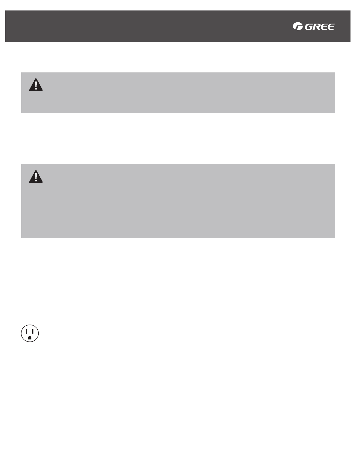
• The power cord is equipped with a 3-prong
grounding plug which can only be used with a
standard 3-prong wall outlet to minimize the
possibility of electric shock hazard. Where
a 2-prong outlet is encountered, it is your
responsibility to have it replaced with a properly
grounded 3-prong wall outlet.
• Do not use the outlet if it is loose or damaged.
It may cause electric shock.
• Do not open the unit during operation. It may cause
electric shock.
• Keep away from heating appliances, flammable
gas, or combustibles such as gasoline, benzene,
thinner, etc.
• Ventilate room before operating air conditioner if
there is a gas leak from another appliance.
• Never use an extension cord, surge protector, or
multi-outlet adapter with this unit.
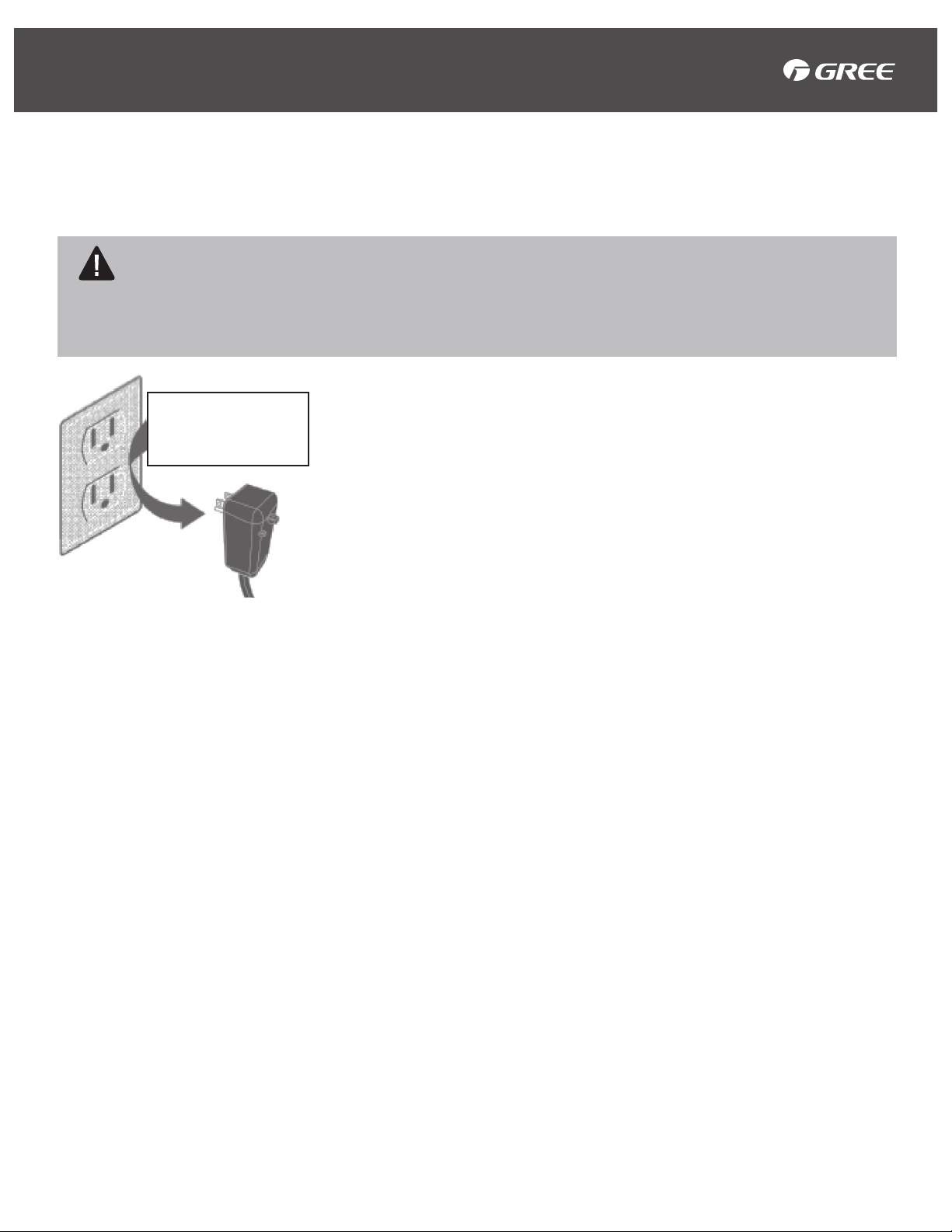
• Plug in power cord properly. Always unplug your air
conditioner by pulling on the power plug. Grip plug
firmly and unplug to remove.
• Do not disassemble or modify the unit.
• Do not operate with wet hands.
• Do not clean with water that may run inside the
units electrical parts. This may cause failure of the
machine or electric shock.
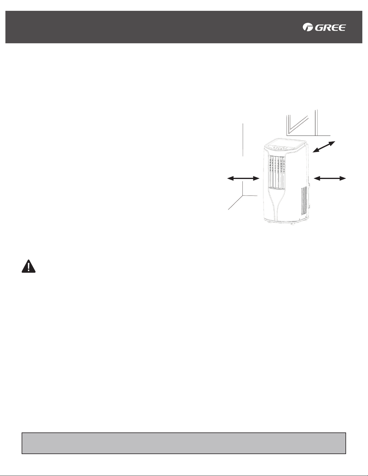
• Do not place obstacles around air-inlets or inside of
air-outlet.
• Switch off the unit and unplug the unit before
cleaning.
• To prevent injury, when the air filter needs to be
removed, do not touch the metal parts of the unit.
• Only clean outside of the unit, use only a mild
detergent.
• Always insert the filters securely. Clean the filter
once every two weeks.
• Do not place heavy objects on the power cord.
Ensure that the power cord is not compressed.
• Turn off the main power switch when not using the
unit for a long period of time.
• All air conditioners contain refrigerants which,
under federal law, must be removed prior to
disposal. If you are getting rid of an old product
with refrigerants, check with the company handling
disposal about what to do.
• These R410A air conditioning systems require
contractors and technicians to use tools, equipment
and safety standards approved for use with this
refrigerant.
WARNING
Please read and understand this entire manual before attempting to assemble, operate or install your
air conditioner. Use this unit only as instructed in this manual. While this manual covers a wide variety
of troubleshooting, the instructions are not meant to cover every situation that may occur. Caution and
common sense are to be practiced when installing, operating or maintaining your unit.
SYMBOL INDICATES A HAZARDOUS SITUATION WHICH IF NOT AVOIDED
COULD RESULT IN SERIOUS INJURY OR DEATH.
SAFETY INFORMATION

4
The power cord with this air conditioner contains a current detection device designed to
reduce the risk of fire. Please refer to the section “operation of current device” for details. In the
event that the power cord is damaged, it cannot be repaired. It must be replaced with a power
cord from the product manufacturer.
Operation of Current Device
The power cord contains a current device that senses damage to the power cord. To test your power
cord, do the following:
1. Plug in the Air Conditioner.
2. The power cord has TWO buttons on the 3-Prong Grounding Plug. Press the TEST button. You will
notice a click as the RESET button pops out.
3. Press the RESET button, and you will hear a click as the button engages.
4. The power cord is now supplying electricity to the unit. (On some products this is also indicated by a
light on the 3-Prong Grounding Plug).
NOTE:
• Do not use the power cord to turn the unit on or off.
• Always make sure the RESET button is pushed in for correct operation.
• The power cord must be replaced if it fails to reset when either the TEST button is pushed,
or it cannot be reset. Please contact Customer Service.
• If the power cord is damaged, then it cannot be repaired. It MUST be replaced with a new power
cord. Please contact Customer Service.
Power Cord with 3-Prong
Grounding Plug and Current
Detection Device.
• The power cord is equipped with a 3-Prong Grounding Plug
which can only be used with a standard 3-prong wall outlet
to minimize the possibility of electric shock hazard. Where a
2-prong outlet is encountered, it is your responsibility to have it
replaced with a properly grounded 3-prong wall outlet.
• Do not use a power cord that shows damage or cracks along
the length or at the connector. A damaged power cord should
be replaced with a new cord obtained from the manufacturer.
Please contact Customer Service for replacement options.
• Do not modify power cord length or share an outlet with another
appliance. This may cause electric shock or fire.
• Always use a dedicated power circuit. The voltage on the outlet
should match the voltage rating on the rating plate.
• Do not use the outlet if it is loose or damaged. It may cause
electric shock.
• Never use an extension cord, surge protector, or multi-outlet
adapter with this unit.
SAFETY INFORMATION
Electrical Information
Do not under any
circumstances cut,
remove, or bypass the
grounding prong

5
CAUTION
When handling the unit be careful to avoid cuts from any sharp metal edges
and the aluminum fins on the front / rear coils.
IMPORTANT: Save these instructions for future reference.
Product failure due to any improper installation is not covered under the One Year Limited Warranty.
IMPORTANT: You MUST use the parts provided for installation as well as proper installation
procedures as described in this manual when installing this Portable Air Conditioner.
WARNING
• Observe all electrical governing codes and ordinances.
• Do not use damaged or non-standard power cords.
• Use caution during installation and maintenance.
• Use proper operation to prevent electric shock, casualty and other accidents.
• Proper installation is the responsibility of the installer. If not installed properly the warranty is void.
• All parts described must be used with no substitutions.
Selection of Installation Location
Installing the unit in the following places can be dangerous and may cause malfunction:
1. Areas with strong heat sources, vapors, flammable or explosive gas, sulfated gas or volatile objects
spread in the air.
2. Near high-frequency devices such as welding machines, medical equipment, etc.
INSTALLATION INSTRUCTIONS
Requirements for Electric Connection
• Follow the Electric Safety Information when installing the unit.
• According to your local safety regulations, use a qualified power circuit.
• Do not plug into an outlet if it is loose or damaged. It may cause electric shock.
• Please make sure the power supply complies with the requirement of air conditioner. Unstable power
supply or wrong wiring may lead to electric shock, hazard or malfunction. Note: Electricity requirements
are 115V (60 Hz).
• Do not connect to the power outlet before finishing installation.
• Please make sure the outlet is always grounded effectively, otherwise it may cause electric shock.
The grounding resistance should comply with national electric safety regulations.
Before You Begin

6
NOTE:
• The description for below installation is for the standard vertical double hung / horizontal sliding
window.
• If you need to install the air conditioner in an over sized window, you may need to use the Extension
Panel and Adjustment Panel. Please refer to requirement of window size for details and Installation
Instructions.
• All parts must be secured to firm wood, masonry, or metal.
• The electrical outlet must be within reach of the power cord.
Where to Install the Unit
• Ensure there is no obstruction near the air-inlet or air-outlet.
• This unit is for indoor use only.
• This unit must be positioned so that the plug is accessible.
• Reserved space around the air conditioner should be at
least 12" (30 cm), see image.
• Place air conditioner on a level and flat surface for operation
and avoid inclining or tipping the unit.
• This unit is equipped with casters.
• Do not place unit on an elevated surface.
12" (30 cm)
12" (30 cm)
12" (30 cm)
INSTALLATION INSTRUCTIONS
NOTICE:
This picture is for reference only. Please refer to the actual product for the appearance.

7
1Control Display
2Horizontal Louver
Adjustment
3Vertical Louver
Adjustment
4Caster
5Power Cord
Storage Hook
6Filter Cover
7Air-inlet
8Exhaust Hose
Connection
9Exhaust Hose
10 Exhaust Nozzle
11 Remote Control
Storage Pocket
12 Drainage Port
12
6
5
7
11
10 9 8
1
2
3
4
INSTALLATION INSTRUCTIONS
Unit Overview
NOTICE:
This picture is for reference only. Please refer to the actual product for the appearance.

8
FAN
AUTO
OPER
HEALTH
AIR
FILTER
TURBO
ON/OFF
X-FAN
HOUR
HUMIDITY
ON/OFF
MODE
FAN
X-FAN
TURBO
TEMP TIMER
SLEEP LIGHT
Window panel
Exhaust cover
Adjustment panel
Extension panel
Tools
Parts
Exhaust Hose
Connection
Pipe Clip
Debris Guard
Foam with Adhesive (2) Remote Control Owner's Manual
AAA Battery (2)
(May Be Pre-Assembled)
Exhaust Hose
Screw (8)
Rain Guard (2)
Drainage Pipe
Drain Connector (1)
Rubber Plug
Bracket
Cord Hook (2)
Pipe Hook (2)
Foam Seal
Exhaust Nozzle Top Exhaust Nozzle
Bottom
INSTALLATION INSTRUCTIONS
Parts and Tools Needed
Tools
Phillips Head Screwdriver Flathead Screwdriver Saw
Tape Measure Scissors Pencil

9
Install the Cord Hooks at the back of the
unit with 2 screws. The top Cord Hook
should face upward, and the bottom
Cord Hook should face downward.
Cord Hook
Screw
1
2
Wind the power cord around
the Cord Hooks.
Note: Do not plug this unit in until
exhaust hose is properly installed
INSTALLATION INSTRUCTIONS
Cord Hook Installation
NOTICE:
This picture is for reference only. Please refer to the actual product for the appearance.

10
Remove the Rubber Plug at the Drainage Port, and fix the Pipe Clip on the right rear side of the unit near
the Drainage Port. Fix the Pipe Clip with a Screw.
Put the Drainage Pipe into the Drainage Port, and tighten the Screw. Then bind with a Pipe Hook.
Put the Rubber Plug into the other side of th Drainage Pipe, connect it with the Pipe Hook, and then
connect it with the Pipe Clip.
Drainage Pipe Installation
1
2
NOTE: Use the continuous drainage option from the bottom hole. Install the drainage
pipe before using, otherwise poor drainage will affect the unit.
Drainage Port
Drainage Pipe
Drainage Pipe
Pipe Hook
Drainage Port Screw
Pipe Clip
Pipe Clip
Pipe Hook
Rubber Plug
INSTALLATION INSTRUCTIONS

11
Debris
Guard
Projection
Prongs
Top
Hole
Rain Guard
4
Connect both Rain Guards to the Debris
Guard. Insert all 3 tabs on the Rain Guard
into the holes in the Debris Guard. Ensure
curved side is on TOP.
Cut the Foam with Adhesive to fit length of
the window and attach to window sill.
Foam with
Adhesive
INSTALLATION INSTRUCTIONS
Vertical Double Hung Window
Attach the Guard Combination to the back side of
the Window Panel. Push the Guard Combination
securely into the Window Panel to ensure that is
fits securely.
Note: Ensure TOP of Guard Combination faces up.
Guard Combination faces the outside.
Tabs
Top Window Panel
Guard Combination
1
3
Open the window and measure the width inside the
window frame.
A) For windows with inner width of 20.5" (52.07 cm)
B) For windows with inner widths over 20.5” (52.07
cm) up to 37.5” (95.2 cm) insert Adjustment Panel
C) For windows with inner widths over 37.5”
(95.2 cm) up to 56.7” (144 cm) insert Adjustment
Panel and Extension Panel.
A
B
C
Extension panel
Adjustment panel
Adjustment panel
Window panel
Exhaust cover
Note: If Extension Panel or Adjustment Panel are
too long, use a Pencil and Saw to cut panels to fit
window frame.
2

12
INSTALLATION INSTRUCTIONS
Vertical Double Hung Window
Cut the Foam Seal to a proper length and seal
the gap between upper part of inner window
sash and outer window sash.
Inner Window Sash
Outer Window
Foam Seal
38.5" - 56.7"
8
Fix the inner window with Bracket and 1
Screw, so that it cannot slide vertically.
It is recommended that you attach the Bracket
to the top of the window sash.
The Window Panel cannot be
installed in windows less than
20.5" (52.07 cm) wide.
Secure the Window Panel to
the window sill with 2 Screws.
Inner width of the window:
20.5" (52.07 cm)- 37.5"
(95.2 cm)
Adjustment Panel was added,
secure the Window Panel to
the window sill with 3 Screws.
Inner width of the window:
37.5" (95.2 cm) - 56.7"
(144 cm)
Adjustment Panel and
Extension Panel were added,
secure the Window Panel to
the window sill with 4 Screws.
5
6
7
Window Sash
Vinyl Window
Wooden Window
Bracket
A) Cut Foam with Adhesive to
length of window and attach
to top of Window Panel.
B) Close window sash
securely against the Window
Panel.
Foam with Adhesive
20.5" 20.5" - 38.5"
AB

13
INSTALLATION INSTRUCTIONS
Horizontal Sliding Window
Tabs
Top
Window Panel
Debris
Guard
Projection
Prongs
Top
Hole
Rain Guard
1
3
4
2
Foam with
Adhesive
Attach the Guard Combination to the back side of
the Window Panel. Push the Guard Combination
securely into the Window Panel to ensure that is fits
securely.
Note: Ensure TOP of Guard Combination faces up.
Guard Combination faces the outside.
Connect both Rain Guards to the Debris
Guard. Insert all 3 tabs on the Rain Guard into
the holes in the Debris Guard.
Ensure curved side is on TOP.
Cut the Foam with Adhesive to fit length of the
window and attach to window sill.
Open the window and measure the height inside the
window frame.
A) For windows with inner height of 20.5" (52.07 cm)
B) For windows with inner height over 20.5” (52.07
cm) up to 37.5” (95.2 cm) insert Adjustment Panel
C) For windows with inner height over 37.5” (95.2 cm)
up to 56.7” (144 cm) insert Adjustment Panel and
Extension Panel.
A
B
C
Extension panel
Adjustment panel
Adjustment panel
Window panel
Exhaust cover
Note: If Extension Panel or Adjustment Panel are
too long, use a Pencil and Saw to cut panels to fit
window frame.

14
INSTALLATION INSTRUCTIONS
Horizontal Sliding Window
20.5" - 38.5"
Vinyl Window
Wooden Window
Cut the Foam Seal to a proper length and seal
the gap between upper part of inner window
sash and outer window sash.
Fix the inner window with Bracket and 1 Screw,
so that it cannot slide horizontally.
7 8
20.5"
38.5" - 56.7"
The Window Panel cannot be
installed in windows less than
20.5" (52.07 cm) high.
Secure the Window Panel to
the window sill with 2 Screws.
Inner height of the window:
20.5" (52.07 cm)- 37.5"
(95.2 cm)
Adjustment Panel was added,
secure the Window Panel to
the window sill with 3 Screws.
Inner height of the window:
37.5" (95.2 cm) - 56.7"
(144 cm)
Adjustment Panel and
Extension Panel were added,
secure the Window Panel to
the window sill with 4 Screws.
5
6A) Cut Foam with Adhesive to
length of window and attach
to top of Window Panel.
B) Close window sash
securely against the Window
Panel.
Foam with Adhesive
AB

15
Exhaust Hose Connection
INSTALLATION AND DISASSEMBLY
1
2
Rotate Exhaust Hose Connection and Exhaust Nozzle clockwise into
opposite ends of the Exhaust Hose.
Slide Exhaust Hose Connection into the grooves located on the back of the unit.
Clockwise
Clockwise
Exhaust Hose
Exhaust Hose
Connection
Exhaust
Nozzle
Bottom
Exhaust
Nozzle
Top
Exhaust Hose
Connection
Clasp
Groove
NOTICE:
This picture is for reference only. Please refer to the actual product for the appearance.

16
Exhaust Hose Removal
3
1 2
Slide open the Exhaust Cover
on the Window Panel and
attach the Exhaust Nozzle.
Remove the Exhaust Nozzle by pushing down on
the sides marked “Push.” Slide close the Exhaust
Cover on the Window Panel.
Note on Installation of Exhaust Hose
In order to improve cooling efficiency, the
Exhaust Hose should be as short as possible,
and without bends.
4
Remove Exhaust Hose Connection by grasping
and lifting the Exhaust Hose Connection upwards.
Clasp
Upwards Disassemble
Exhaust
Hose
Connection
INSTALLATION AND DISASSEMBLY
Exhaust Hose Connection
NOTICE:
This picture is for reference only. Please refer to the actual product for the appearance.

17
LCD Remote Control
LCD remote control displays all settings.
X-Fan Button On Remote Control
By pressing this button in COOL or DRY mode the Icon “ ” will be displayed and the interior fan will
continue to operate for a few minutes in order to disperse excess condensation. This mode is not
available in AUTO or FAN mode. Press this button again to turn off X-FAN mode.
Programmable Digital Thermostat
For precise comfort control. Select the exact desired temperature for maximum comfort.
24 Hour Programmable Clock Timer
While in OFF mode enables user to set a specific time for the unit to turn on. When in ON mode enables
user to set a specific time for unit to turn off.
3 Speed Fan & Auto Fan
Allows for more comfort settings. Auto fan automatically sets the fan speed based on the current room
temperature and thermostat setting for maximum comfort.
Sleep Mode
Automatically increases the set temperature 2°F after the first hour and another 2°F after the second hour.
This feature limits compressor usage and conserves energy.
Loss of Power Protection with Auto Restart
Remembers all settings when power is interrupted. As soon as power is restored, the A/C will operate in
the mode, temperature and settings prior to power loss.
Evaporative Exhaust Technology and Evaporative Dehumidifier (DRY Mode)
Evaporative technology removes moisture from the air and drips onto the condenser. The condenser
evaporates the water and blows it out of the exhaust hose with the hot air. If the water is not fully
evaporated it is dripped into a small pan and then pumped back up to be evaporated by the condenser.
Child Lock Function
Pressing “+” and “-” buttons simultaneously can turn on or turn off child lock function. When child lock
function is started up, “ “ icon will be displayed on remote control and will not send signal.
NOTE: The default temperature reading on the display is degree Fahrenheit (°F). To change the display to degree Celsius
(°C) with the remote, press the Mode and Temp Decrease buttons simultaneously and hold for 3 seconds when the
remote is turned off. Repeat the process to change back to degree Fahrenheit (°F). This cool-only air conditioner was not
designed for freezing outdoor conditions. Do not use in freezing outdoor conditions.
OPERATING INSTRUCTIONS
Features of Your Portable A/C

18
OPERATING INSTRUCTIONS
Function & Control Display
SYMBOL DESCRIPTION FUNCTION
Power Button Turns air conditioner On and Off.
Display
When turned on, the display will show the set temperature, or time remaining
on the Delay Timer. Shows the Set Temperature while setting the temperature in
COOL mode.
Temp Increase
/Decrease Buttons
In COOL mode, press (+) or (-) button to increase or decrease the set temperature
by 1°F. Set temperature range is 61°F (16.1 °C) to 86°F. (30 °C) Under DRY, or
FAN mode, this button is inactive.
Mode Button
Cycles through COOL, DRY, FAN.
COOL: Under this mode, cooling mode indicator is on. Temperature settings
range from 61°F (16.1 °C) to 86°F. (30 °C).
Fan Speed Button Changes the fan speed. Choose between Low, Med, High, Auto.
Note: Cannot be used in DRY Mode
Timer Button When the unit is OFF, the timer can be set automatically to turn ON the unit. Timer
setting range is .5 (30 min) - 24 hours.
Sleep Button
Press this button to enter into sleep mode. If unit operates in COOL Mode, after
SLEEP Mode is turned on, preset temperature will increase by 2°F within 1 hour;
preset temperature will increase by 4°F after 2 hours. Unit will operate at this
temperature until shut off. Sleep function is not available for FAN Mode, DRY
Mode.
NOTICE:
This picture is for reference only. Please refer to the actual product for the appearance.
Mode
Button
On/Off
Button
Sleep
Button
Fan
Speed
Fan
Mode
Dry Mode
Cool Mode
Display+ / - Button
Fan
Button
Timer
Button

19
SYMBOL DESCRIPTION FUNCTION
Power Button Turns air conditioner On and Off.
Mode Button Press button to select a mode from the following options:
COOL, DRY, FAN.
Temp Increase
/Decrease
Buttons
Pressing (+) or (-) button once will increase or decrease set temperature by 1°. Hold
(+) or (-) button for 2 seconds, to quickly adjust the temperature on the remote control.
Fan Button
This button is used for setting Fan Speed in the following sequence:
AUTO- Speed 1- Speed 2- Speed 3
X-Fan Button
By pressing this button in COOL or DRY mode the Icon “ ” will be displayed and
the interior fan will continue to operate for a few minutes in order to disperse excess
condensation. This mode is not available in AUTO or FAN mode.
Press this button again to turn off X-FAN mode.
Sleep Button
Press this button to enter into sleep mode. If unit operates in COOL Mode, after
SLEEP Mode is turned on, preset temperature will increase by 2°F within 1 hour;
preset temperature will increase by 4°F after 2 hours. Unit will operate at this
temperature until shut off. Sleep function is not available for FAN Mode, DRY Mode.
Timer Button
Press this button to initiate Auto—ON/AUTO—OFF timer. Press this button twice to
cancel auto-timer.
Note: Time Setting range is .5 (30 min) - 24 hours.
NOTICE:
• The distance between remote
and receiving window should be
no more than 8 m (26 ft.), and
there should be no obstacles
between them.
• When not using the remote
control for extended periods
of time, please take out the
batteries.
OPERATING INSTRUCTIONS
Remote Control Operation

20
Vertical Louver Adjustment
Hold the Vertical Louver as shown
in the diagram and adjust the air
flow direction.
To Change Air Flow Direction
Horizontal Louver Adjustment
Hold the Horizontal Louver as
shown in the diagram and adjust
the air flow direction.
CAUTION:
Do not adjust the Vertical Louver to the lowest or the highest in the COOL or DRY mode with
the fan speed set to Low for an extended period of time. Condensation may form on the louvers.
CAUTION:
Do not adjust the Horizontal Louver to the extreme left or right position in the COOL or DRY
mode with the fan speed set to Low for an extended period of time. Condensation may form on the louvers.
OPERATING INSTRUCTIONS
NOTICE:
This picture is for reference only. Please refer to the actual product for the appearance.
Table of contents
Other Gree Air Conditioner manuals

Gree
Gree GJC05BJ-A3MNE1A User manual

Gree
Gree FGR20Pd/DNa-X User manual

Gree
Gree VERSATI III Series User manual

Gree
Gree GMV-VDR5PH/SA-S User manual

Gree
Gree GRS-CQ4.0Pd/NhG-K User manual

Gree
Gree GWHD(14)NK6LO User manual

Gree
Gree GWH18QD-K3DNA3G User manual

Gree
Gree GUD36W/A-D User manual

Gree
Gree GWH09AEC-K6DNA1A User manual

Gree
Gree GMV-ND18PHS/A-T User manual

Gree
Gree Cozy Series User manual

Gree
Gree GWH12YD-S6DBA1A User manual

Gree
Gree FLR09HP230V1BF User manual

Gree
Gree NCHS2D User manual

Gree
Gree GPC07AJ-A3NNA1A User manual

Gree
Gree GWH09YD-S6DBA2A User manual

Gree
Gree FP-34WA/G-K User manual

Gree
Gree GWH09AECXB-K6DNA1A User manual

Gree
Gree NCHS1B(U) User manual

Gree
Gree GWC09KF-D3DNXXA User manual