Greystone Energy Systems TE200AD Series User manual
Other Greystone Energy Systems Temperature Controllers manuals
Greystone Energy Systems
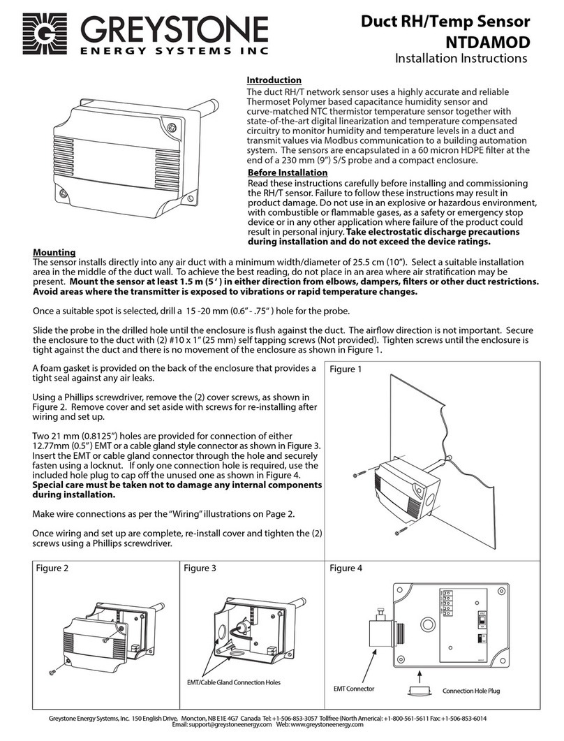
Greystone Energy Systems NTDAMOD User manual
Greystone Energy Systems
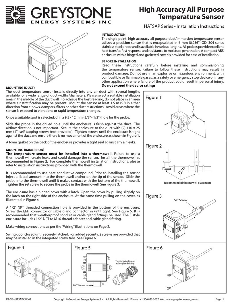
Greystone Energy Systems HATSAP Series User manual
Greystone Energy Systems
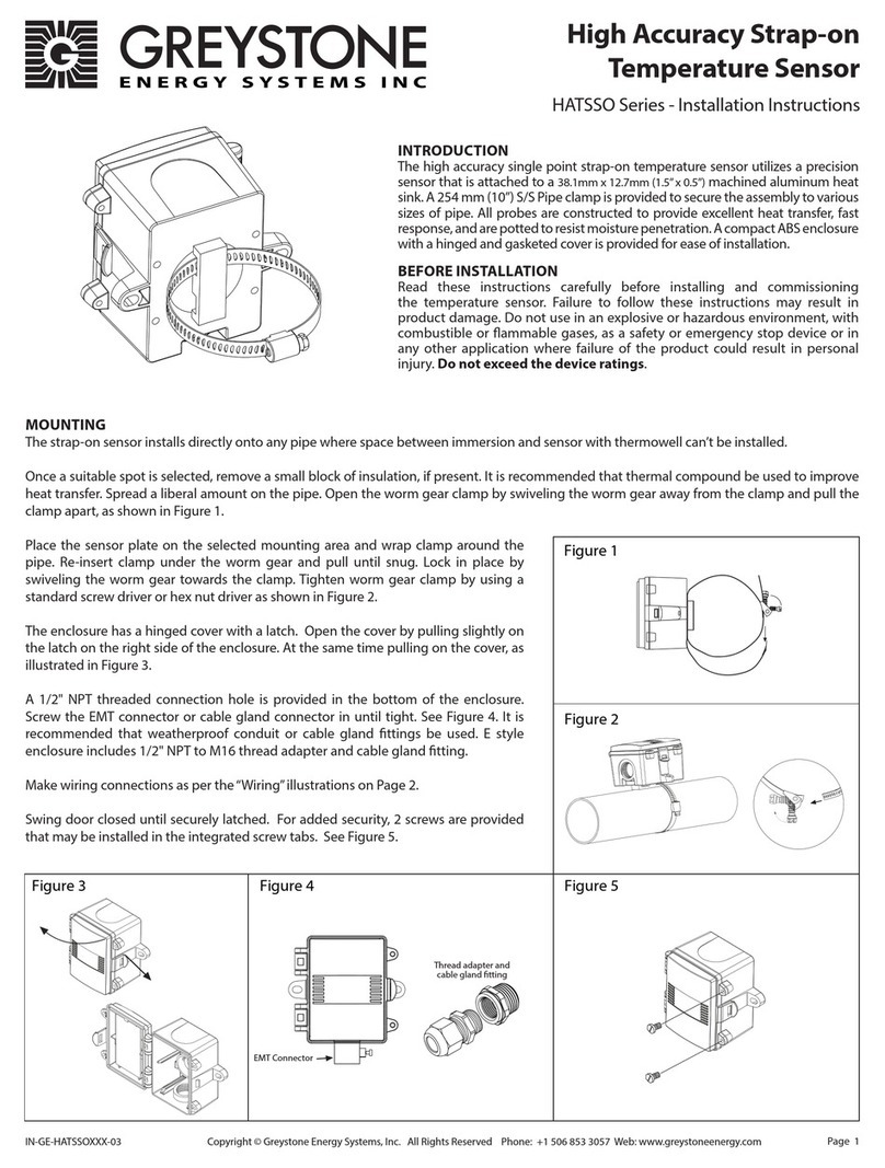
Greystone Energy Systems HATSSO Series User manual
Greystone Energy Systems
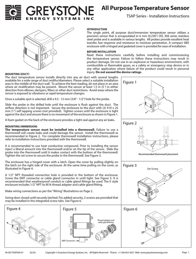
Greystone Energy Systems TSAP Series User manual

Greystone Energy Systems
Greystone Energy Systems HATSOB Series User manual
Greystone Energy Systems
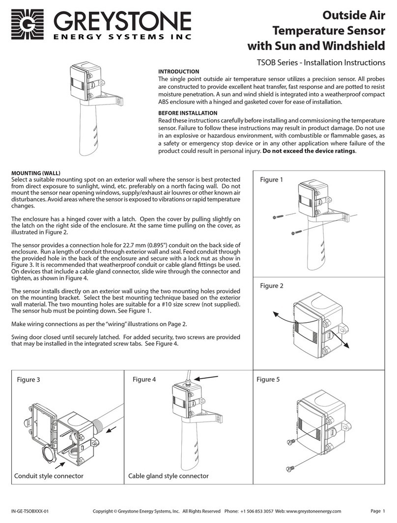
Greystone Energy Systems TSOB Series User manual
Greystone Energy Systems
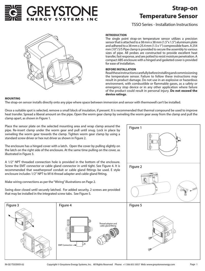
Greystone Energy Systems TSSO Series User manual
Greystone Energy Systems
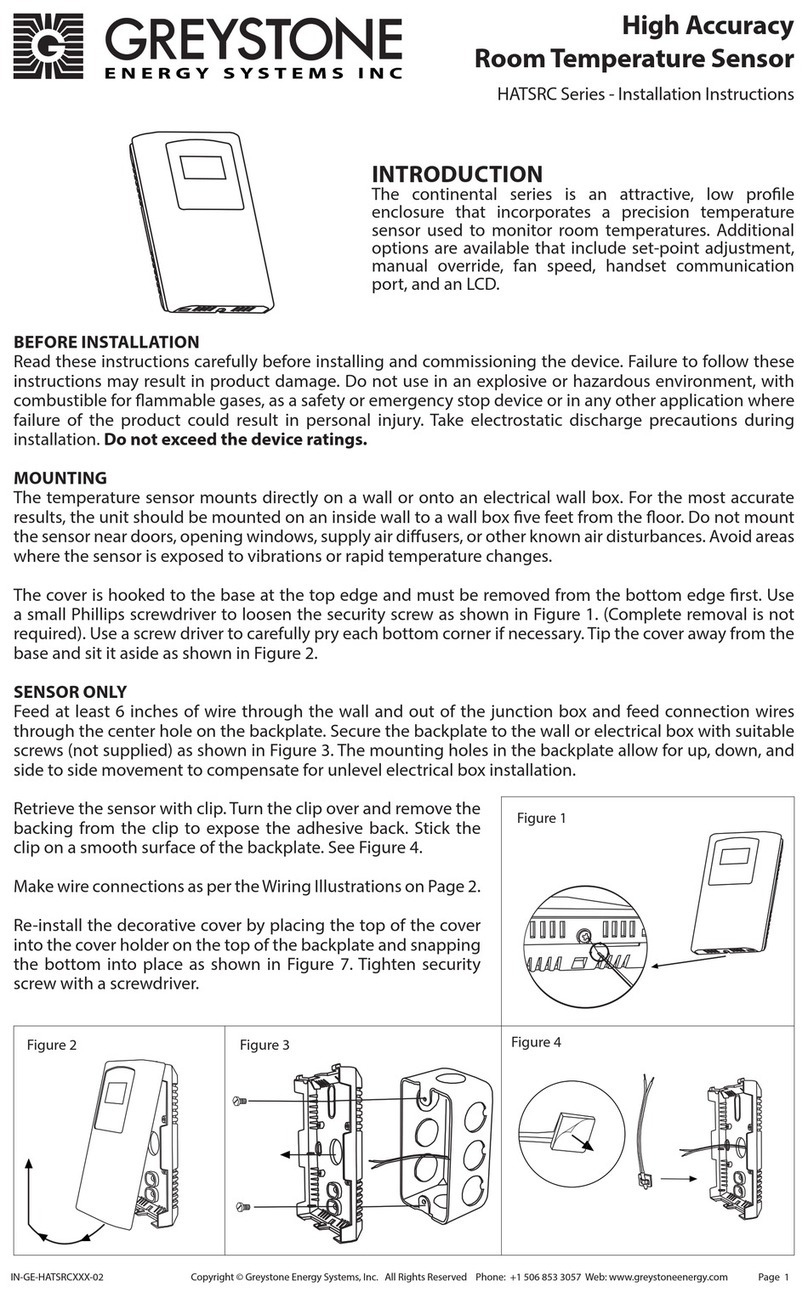
Greystone Energy Systems HATSRC Series User manual
Greystone Energy Systems
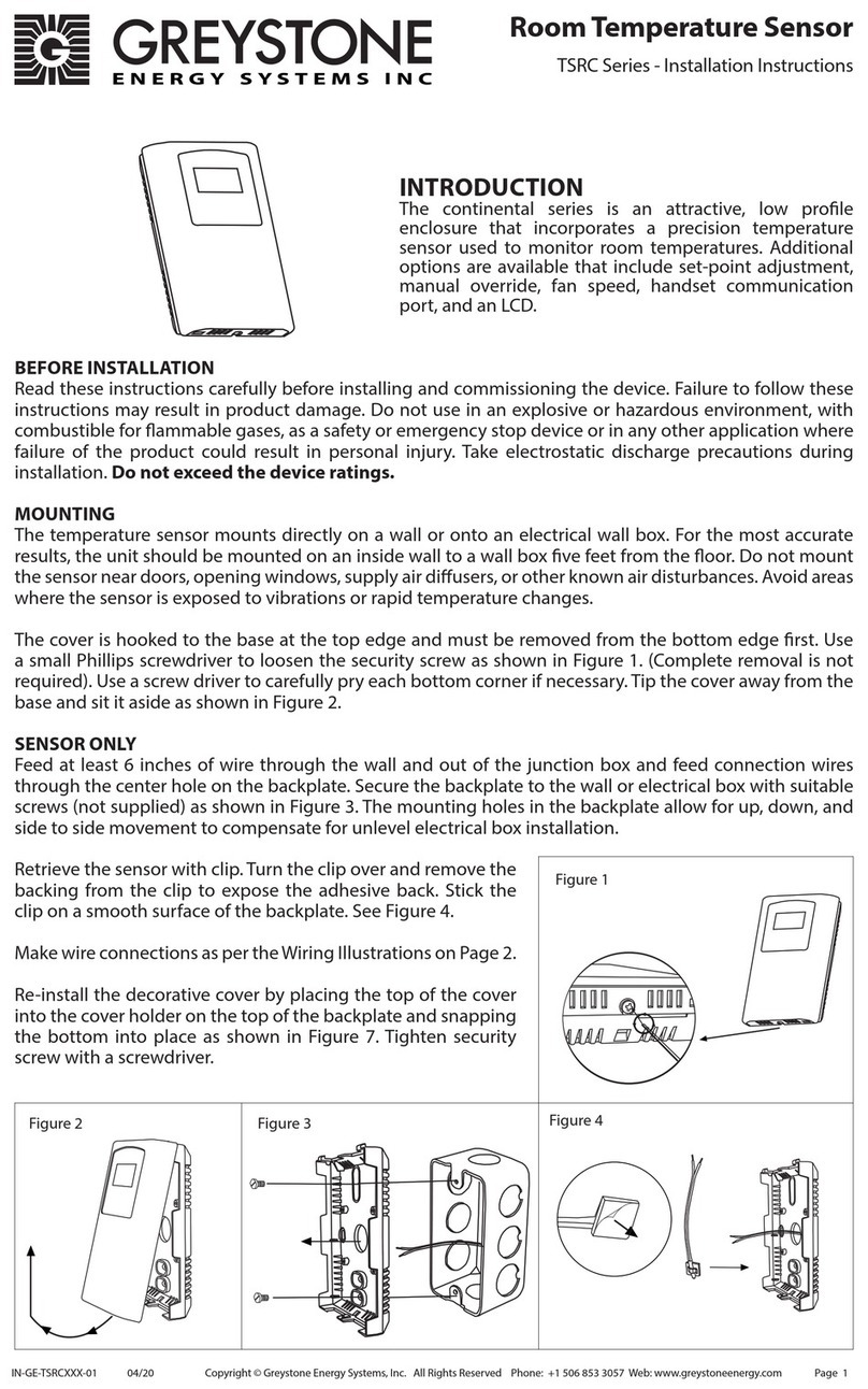
Greystone Energy Systems TSRC Series User manual
Popular Temperature Controllers manuals by other brands

P.W. KEY
P.W. KEY rt-208gt operating manual

BH Thermal
BH Thermal BriskONE owner's manual

West Control Solutions
West Control Solutions KS 45 Operation Notes

MCS
MCS RITC-15B Operator's manual

SMC Networks
SMC Networks Thermo-con INR-244-639 Operation manual

eltherm
eltherm Ex-TC It Series operating instructions

Omron
Omron C200H-TV Series Operation manual

industrie technik
industrie technik CA1 instructions

KRAL
KRAL EET 32 operating instructions

dixell
dixell XR420C Installing and operating instructions

Opt Lasers
Opt Lasers TEC-8A-24V-PID-HC operating manual

Vaillant
Vaillant VR 92/3 Operating and installation instructions


