manuals.online logo
Brands
  1. Home
  2. •
  3. Brands
  4. •
  5. Greystone Energy Systems
  6. •
  7. Temperature Controllers
  8. •
  9. Greystone Energy Systems HATSSO Series User manual

Greystone Energy Systems HATSSO Series User manual

Page 1
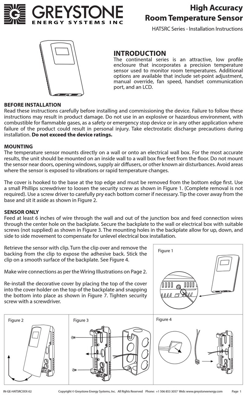
INTRODUCTION
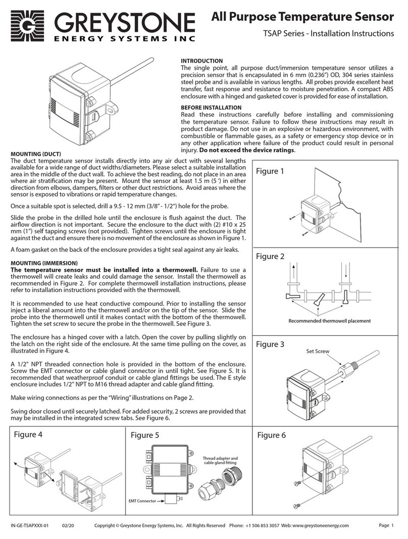
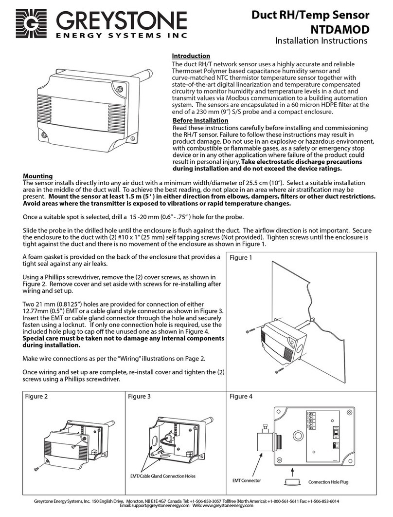
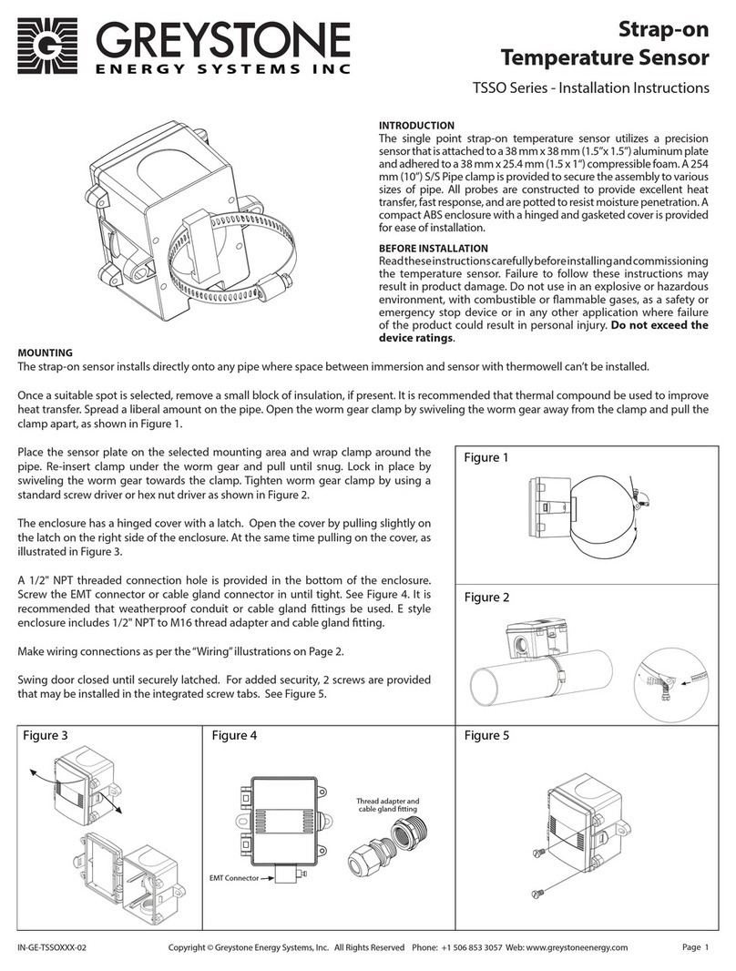
The high accuracy single point strap-on temperature sensor utilizes a precision
sensor that is attached to a 38.1mm x 12.7mm (1.5” x 0.5”) machined aluminum heat
sink. A 254 mm (10”) S/S Pipe clamp is provided to secure the assembly to various
sizes of pipe. All probes are constructed to provide excellent heat transfer, fast
response, and are potted to resist moisture penetration. A compact ABS enclosure
with a hinged and gasketed cover is provided for ease of installation.
BEFORE INSTALLATION
Read these instructions carefully before installing and commissioning
the temperature sensor. Failure to follow these instructions may result in
product damage. Do not use in an explosive or hazardous environment, with
combustible or ammable gases, as a safety or emergency stop device or in
any other application where failure of the product could result in personal
injury. Do not exceed the device ratings.
MOUNTING
The strap-on sensor installs directly onto any pipe where space between immersion and sensor with thermowell can’t be installed.
Once a suitable spot is selected, remove a small block of insulation, if present. It is recommended that thermal compound be used to improve
heat transfer. Spread a liberal amount on the pipe. Open the worm gear clamp by swiveling the worm gear away from the clamp and pull the
clamp apart, as shown in Figure 1.
Place the sensor plate on the selected mounting area and wrap clamp around the
pipe. Re-insert clamp under the worm gear and pull until snug. Lock in place by
swiveling the worm gear towards the clamp. Tighten worm gear clamp by using a
standard screw driver or hex nut driver as shown in Figure 2.
The enclosure has a hinged cover with a latch. Open the cover by pulling slightly on
the latch on the right side of the enclosure. At the same time pulling on the cover, as
illustrated in Figure 3.
A 1/2" NPT threaded connection hole is provided in the bottom of the enclosure.
Screw the EMT connector or cable gland connector in until tight. See Figure 4. It is
recommended that weatherproof conduit or cable gland ttings be used. E style
enclosure includes 1/2" NPT to M16 thread adapter and cable gland tting.
Make wiring connections as per the “Wiring”illustrations on Page 2.
Swing door closed until securely latched. For added security, 2 screws are provided
that may be installed in the integrated screw tabs. See Figure 5.
EMT Connector
Thread adapter and
cable gland tting
Figure 1
Figure 3 Figure 4 Figure 5
Figure 2
IN-GE-HATSSOXXX-03 Copyright © Greystone Energy Systems, Inc. All Rights Reserved Phone: +1 506 853 3057 Web: www.greystoneenergy.com
High Accuracy Strap-on
Temperature Sensor
HATSSO Series - Installation Instructions
Page 2
WIRING
• Use 18 - 24 AWG shielded wiring for all connections. Do not locate the device wires in the same conduit with wiring used to supply inductive
loads such as motors. Make all connections in accordance with national and local codes.
• Pull at least six inches of wire into the enclosure, then complete the wiring connection according to wiring diagrams below.
• Thermistors are a 2 wire hook up and are not polarity sensitive. See Figure 6.
• RTD’s are a 3 wire hook up see Figure 7.
SPECIFICATIONS:
Sensor Type:................................... Various thermistors or RTD
Sensor Accuracy:......................... RTD Class A: ±0.15°C (±0.27°F) @ 0°C (32°F)
RTD 1/3 DIN: ±0.1°C (±0.18°F) @ 0°C (32°F)
RTD 1/10 DIN: ±0.03°C (±0.054°F) @ 0°C (32°F)
NTC Thermistor Type 39: ±0.05°C (±0.09°F), 0 to 70°C (32 to 158°F)
NTC Thermistor Type 55: ±0.03°C (±0.054°F),
0 to 70°C (32 to 158°F)
NTC Thermistor Type 40/46: ±0.1°C (±0.18°F),
0 to 70°C (32 to 158°F)
Probe Material:............................. Machined aluminum heat sink
Probe Dimensions:..............38.1mm x 12.7mm (1.5”x 0.5”)
Probe Sensing Range:............... RTD: -20 to 100°C (-4 to 212°F)
Thermistors: -40 to 100°C (-40 to 212°F)
Ambient Operating Range:.... -40 to 50°C (-40 to 122°F)
Probe Size: ...................................... 38 mm (1.5") square
Wire Material:................................ RTD: FT-4, 22 AWG, 3 Wire
Thermistor: PVC insulated, parallel bonded, 22 AWG, 2 Wire
Enclosure:........................................ A: ABS, UL94-V0, IP65 (NEMA4X)
C: Same as A, with terminal block
E: Same as C, with thread adapter (1/2" NPT to M16),
cable gland tting, and terminal block
Termination: .................................. A: Pigtail, 2 or 3 wire
C & E: terminal block, 2 or 3 wire
Country of Origin:....................... Canada
PRINTED IN CANADA
TYPICAL WIRE RESISTANCE VALUES
When using low resistance sensors, long wire runs can add signicant error
to the readings. Use the following chart to determine errors due to wire
resistance or consider using a 1000 ohm sensor or a transmitter for better
accuracy. Locate the type of wire being used. Multiply the total length of the
wire (distance from the controller to the sensor and back) by the number
found in the chart below for total resistance.
Figure 6 2 Wire Termination for Thermistor
Figure 7 3 Wire Termination for RTD
ToController
Analog Input (AI)
(No Polarity)
ToController
Analog Input (AI)
(No Polarity)
ToController
Analog Input (AI) or
Customer supplied
transmitter
ToController
Analog Input (AI) or
Customer supplied
transmitter
Green
Red
Black
EMT Connector
EMT Connector
ToController
Analog Input (AI)
(No Polarity)
ToController
Analog Input (AI)
(No Polarity)
ToController
Analog Input (AI) or
Customer supplied
transmitter
ToController
Analog Input (AI) or
Customer supplied
transmitter
Green
Black
Red
EMT Connector
EMT Connector
Wiring for Enclosures C & E
*For illustrative purposes only, terminal block mounted on inside of cover
*
*
GAUGE WIRE TYPE 18 AWG 22 AWG 24 AWG
STRANDED (OHMS/FOOT) 5.85 mΩ 14.75 mΩ 23.29 mΩ
SOLID (OHMS/FOOT) 6.4 mΩ 15.85 mΩ 25.72 mΩ
NOTE: The sensor accuracies listed in the specications section apply to the
sensing element only prior to product assembly and may not be reected in
the complete assembly.
Due to the measurement uncertainty, it is possible, that the true resistance
value of the single delivered sensor at 0°C can be out of the dened tolerance
class. Proling each assembly to take into consideration lead wire and the
attachment method should be completed.
DIMENSIONS
69.8 mm
2.75"
76.2 mm
3.00"
82.5 mm
3.25"
52.0 mm
2.05"
28.6 mm
1.125"
0.5" NPT
254 mm (10")
S/S Pipe Clamp
Quick Release
Machined Aluminum
Heat Sink
IN-GE-HATSSOXXX-03 Copyright © Greystone Energy Systems, Inc. All Rights Reserved Phone: +1 506 853 3057 Web: www.greystoneenergy.com

Other Greystone Energy Systems Temperature Controllers manuals

Greystone Energy Systems TE200AD Series User manual

Greystone Energy Systems

Greystone Energy Systems TE200AD Series User manual

Greystone Energy Systems HATSOB Series User manual

Greystone Energy Systems

Greystone Energy Systems HATSOB Series User manual

Greystone Energy Systems TSSO Series User manual

Greystone Energy Systems

Greystone Energy Systems TSSO Series User manual

Greystone Energy Systems TSOB Series User manual

Greystone Energy Systems

Greystone Energy Systems TSOB Series User manual

Greystone Energy Systems TSAP Series User manual

Greystone Energy Systems

Greystone Energy Systems TSAP Series User manual

Greystone Energy Systems HATSRC Series User manual

Greystone Energy Systems

Greystone Energy Systems HATSRC Series User manual

Greystone Energy Systems NTDAMOD User manual

Greystone Energy Systems

Greystone Energy Systems NTDAMOD User manual

Greystone Energy Systems TSRC Series User manual

Greystone Energy Systems

Greystone Energy Systems TSRC Series User manual

Greystone Energy Systems HATSAP Series User manual

Greystone Energy Systems

Greystone Energy Systems HATSAP Series User manual

Popular Temperature Controllers manuals by other brands

DAVIS 6832 user manual

DAVIS

DAVIS 6832 user manual

Sollatek JEA Series user manual

Sollatek

Sollatek JEA Series user manual

Mindfield eSense user manual

Mindfield

Mindfield eSense user manual

ACS TCO manual

ACS

ACS TCO manual

Dimplex BRTU 101 UN Operating instructions and system description

Dimplex

Dimplex BRTU 101 UN Operating instructions and system description

Domotec Therm-Control DHB 370 C Installation notes

Domotec

Domotec Therm-Control DHB 370 C Installation notes

E+E Elektronik EE431 user manual

E+E Elektronik

E+E Elektronik EE431 user manual

Motorola HMTS1050 Specifications

Motorola

Motorola HMTS1050 Specifications

Kiwi LAS-604V2 user manual

Kiwi

Kiwi LAS-604V2 user manual

Viessmann OpenTherm operating instructions

Viessmann

Viessmann OpenTherm operating instructions

Bosch EMS plus MM100 installation instructions

Bosch

Bosch EMS plus MM100 installation instructions

Ascon tecnologic e34B operating instructions

Ascon tecnologic

Ascon tecnologic e34B operating instructions

AFRISO CosiTherm FT operating instructions

AFRISO

AFRISO CosiTherm FT operating instructions

Regin TG-R5W Instruction

Regin

Regin TG-R5W Instruction

Omron E5AN datasheet

Omron

Omron E5AN datasheet

Chromalox 1601 user manual

Chromalox

Chromalox 1601 user manual

Full Gauge Controls MICROSOL II plus manual

Full Gauge Controls

Full Gauge Controls MICROSOL II plus manual

Netatmo Healthy home coach quick start guide

Netatmo

Netatmo Healthy home coach quick start guide

manuals.online logo
manuals.online logoBrands
  • About & Mission
  • Contact us
  • Privacy Policy
  • Terms and Conditions

Copyright 2025 Manuals.Online. All Rights Reserved.