D+H ZA 35-HS User manual

Standard version
Version without tube (option "-OT")
Please order bracket sets separately
B 08 11 22802 026
G 500001
ZA 35/85/105/155-BSY+(-HS) instructions

ZA-BSY+
ZA-BSY+ 7/20
English
Intended use
- Rack and pinion drive for electric opening and
closing of windows and flaps in the facade and
roof area
- Operating voltage 24 V DC
- Useable for smoke ventilation, D+H Euro-SHEV
according to DIN EN 12101-2 as well as daily
natural ventilation
- Only for inside mounting
Performance features
- Micro processor controlled synchro electronics
BSY + for a precise synchronous run of up to
8 drives
- Individually programmable (via software SCS)
- SHEV-high speed function (fast-running
feature in OPEN-direction)
- Protection system for the main closing edge
- Especially silent in ventilation operation
because of reduced motor speed
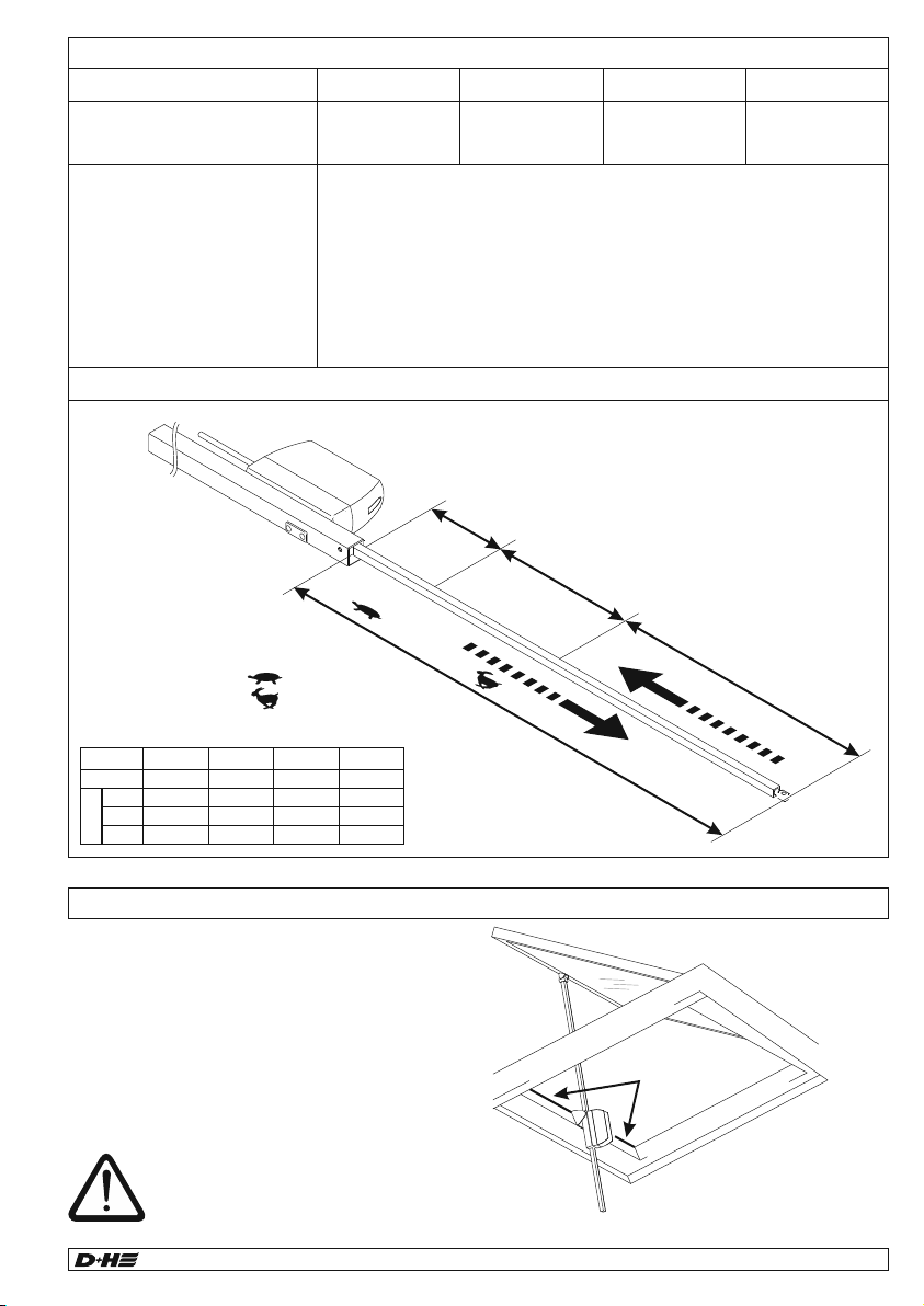
Drive unit with 2,5 m silicone cable. Dependent on
the type of window, different bracket sets are
available separately.
Extent of supply
500
600
800
1000
1100
1200
1300
1400
1500
1600
0
200
400
600
800
1000
1200
1400
max. Load (N)
Stroke (mm)
Permanent
Temporary
Pressure load diagram
Maximum pressure load of the toothed rack is not
automatically identical with maximum pressure force
of the drive!
Loads from over 1000 N to 1500 N are only briefly
permissible (e.g. to throwing off snow or with wind
loads). These may arise up to a stroke of 800 mm.
Safety notes
Safety extra low voltage 24 V DC!
Do not connect directly to the mains supply!
- Connection has to be carried out only by an
authorized electrical specialist
- Danger of violent pressure in handaccessible area
- Keep away People from the operating area of the
drive
- Keep away children from the control
- Observe pressure load diagram of the toothed rack!
- Only for inside mounting.
Use rain detector with danger of rain
(e.g. at domelights or roof windows)
- Use option “-W“ in case of outside mounting!
- Just use unchanged original D+H parts
- Observe mounting instructions of bracket set!
Observe enclosed r ed safety slip!
99.824.31 1.4/04/16
Closing edge protection
Main closing edge
Beside closing edge
Beside closing edge
In "CLOSE" direction the drive has an active
protection for the main closing edge. With an
overload in the closing range 3 and 2 the drive runs
"OPEN" for 10 seconds, then drive "CLOSE" again. If
after three attempts a closing is not possible, the
drive remains in this position.
In addition, the drive has a passive protection. The
closing speed in closure Range 2 and 1 is reduced to
5 mm/s.
Higher forces can occur on besides
closing edges. Danger of violent
pressure in handaccessible area.
WARNING
Read all safety warnings, instructions, illustrations
and specifications provided with this product.
Failure to follow all instructions listed below may
result in electric shock, fire and/or serious injury.
Save all warnings and instructions for future
reference.
Type ZA 35-BSY+(-HS) ZA 85-BSY+(-HS) ZA 105-BSY+(-HS) ZA 155-BSY+(-HS)
Power supply 24 V DC, ±15% 24 V DC, ±15% 24 V DC, ±15% 24 V DC, ±15%
Nominal current 0,5 A (1,2 A) 1,0 A (2,0 A) 1,2 A (2,2 A) 1,4 A (2,5 A)
Nominal force 300 N 800 N 1000 N 1500 N
Nominal locking force 1100 N
Lifetime >20 000 double strokes
Duty cycle 30 % (With cycle time 10 minutes)
Housing Aluminium powder-coated (~RAL 9006), polycarbonate
Ingress protection IP 65 (“-W“ = IP 54)
Temperature range -5 ... +75°C
Fire stability 30 min / 300°C
Emission sound pressure level LpA ≤ 70 dB(A)
Nominal stroke length* see type plate
Additional functions * closing edge protection activated (3 stroke repeatings)
* Programmable with software SCS
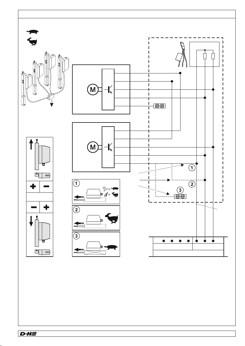
Running speed and forces
Normal operation =
SHEV- fast running =
IIII
77mm
23mm
7,1 mm/s
5 mm/s
5 mm/s
~7,1 mm/s / ~8 mm/s (~17 mm/s)
II
Closure Ranges
Technical data
All forces
+ approx. 20 % switch-off reserve
(temporary)
OPEN
Forces
CR III
CR II
CR I
300 N
300 N
300 N
300 N
800 N
800 N
800 N
800 N
1000 N
1000 N
1000 N
800 N
1500 N
1000 N
1000 N
800 N
ZA 35 ZA 85 ZA 105 ZA 155
CLOSE
ZA-BSY+
6/20 ZA-BSY+
English
Intended use
- Rack and pinion drive for electric opening and
closing of windows and flaps in the facade and
roof area
- Operating voltage 24 V DC
- Useable for smoke ventilation, D+H Euro-SHEV
according to DIN EN 12101-2 as well as daily
natural ventilation
- Only for inside mounting
Performance features
- Micro processor controlled synchro electronics
BSY + for a precise synchronous run of up to
8 drives
- Individually programmable (via software SCS)
- SHEV-high speed function (fast-running
feature in OPEN-direction)
- Protection system for the main closing edge
- Especially silent in ventilation operation
because of reduced motor speed
Drive unit with 2,5 m silicone cable. Dependent on
the type of window, different bracket sets are
available separately.
Extent of supply
500
600
800
1000
1100
1200
1300
1400
1500
1600
0
200
400
600
800
1000
1200
1400
max. Load (N)
Stroke (mm)
Permanent
Temporary
Pressure load diagram
Maximum pressure load of the toothed rack is not
automatically identical with maximum pressure force
of the drive!
Loads from over 1000 N to 1500 N are only briefly
permissible (e.g. to throwing off snow or with wind
loads). These may arise up to a stroke of 800 mm.
Safety notes
Safety extra low voltage 24 V DC!
Do not connect directly to the mains supply!
- Connection has to be carried out only by an
authorized electrical specialist
- Danger of violent pressure in handaccessible area
- Keep away People from the operating area of the
drive
- Keep away children from the control
- Observe pressure load diagram of the toothed rack!
- Only for inside mounting.
Use rain detector with danger of rain
(e.g. at domelights or roof windows)
- Use option “-W“ in case of outside mounting!
- Just use unchanged original D+H parts
- Observe mounting instructions of bracket set!
Observe enclosed red safety slip!
99.824.31 1.4/04/16
Closing edge protection
Main closing edge
Beside closing edge
Beside closing edge
In "CLOSE" direction the drive has an active
protection for the main closing edge. With an
overload in the closing range 3 and 2 the drive runs
"OPEN" for 10 seconds, then drive "CLOSE" again. If
after three attempts a closing is not possible, the
drive remains in this position.
In addition, the drive has a passive protection. The
closing speed in closure Range 2 and 1 is reduced to
5 mm/s.
Higher forces can occur on besides
closing edges. Danger of violent
pressure in handaccessible area.
WARNING
Read all safety warnings, instructions, illustrations
and specifications provided with this product.
Failure to follow all instructions listed below may
result in electric shock, fire and/or serious injury.
Save all warnings and instructions for future
reference.
Type ZA 35-BSY+(-HS) ZA 85-BSY+(-HS) ZA 105-BSY+(-HS) ZA 155-BSY+(-HS)
Power supply 24 V DC, ±15% 24 V DC, ±15% 24 V DC, ±15% 24 V DC, ±15%
Nominal current 0,5 A (1,2 A) 1,0 A (2,0 A) 1,2 A (2,2 A) 1,4 A (2,5 A)
Nominal force 300 N 800 N 1000 N 1500 N
Nominal locking force 1100 N
Lifetime >20 000 double strokes
Duty cycle 30 % (With cycle time 10 minutes)
Housing Aluminium powder-coated (~RAL 9006), polycarbonate
Ingress protection IP 65 (“-W“ = IP 54)
Temperature range -5 ... +75°C
Fire stability 30 min / 300°C
Emission sound pressure level LpA ≤ 70 dB(A)
Nominal stroke length* see type plate
Additional functions * closing edge protection activated (3 stroke repeatings)
* Programmable with software SCS
Running speed and forces
Normal operation =
SHEV- fast running =
IIII
77mm
23mm
7,1 mm/s
5 mm/s
5 mm/s
~7,1 mm/s / ~8 mm/s (~17 mm/s)
II
Closure Ranges
Technical data
All forces
+ approx. 20 % switch-off reserve
(temporary)
OPEN
Forces
CR III
CR II
CR I
300 N
300 N
300 N
300 N
800 N
800 N
800 N
800 N
1000 N
1000 N
1000 N
800 N
1500 N
1000 N
1000 N
800 N
ZA 35 ZA 85 ZA 105 ZA 155
CLOSE
A synchron-group (ZA-BSY+) can be count up to 8
drives, which communicate by a bus. Each drive has
it’s own adress. This adress is configurable with
SCS.
The last drive of a synchron-group is the master,
which controls the other drives, the slaves. Different
forces between the drives of a group will balanced
with intelligent force- and position control. In case of
malfunction respective cutoff of a drive, all drives will
shut down from the master-drive.
Functional description
ZA-BSY+
ZA-BSY+ 9/20
English
Visual inspection:
Only one master-drive allowed.
The master has, according to common drives,
the last adress.
The adress is sticked on the drive. Slaves are
nubered downwards.
Example: In a group, composed of 3 drives,
there is a master 3, a slave 2 and a slave 1drive.
Attention: only applies by factory set. as soon as
the drives were reprogramized with SCS
he factory set adressing does not apply any
longer.
Wiring:
Is the group wired correctly?
Therefore look connection diagrams.
Null balance:
It should be null balanced.
Software SCS or the special magnet
MAG 502 is required.
Call D+H Service:
Drives must be configured.
Software SCS is required.
Trouble shooting
99.824.31 1.4/04/16
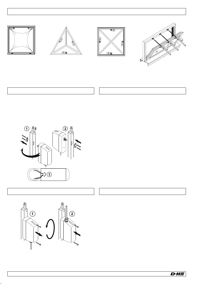
Mounting examples
Triangular pyramid *
Domelight Pyramid * Weighty wing
Uncritical load distribution Critical load distribution
* Guiding device required by customer in case of complete lift-off of pyramid/domelight,
because of possible lateral load due to wind pressure!
Shifting of drive cable
Disconnect drive from electric voltage!
1. Move out toothed rack about 10 ... 20 mm.
Disconnect drive from electric Voltage!
2. Take off drive unit and shift
3. Attention! Moving direction of drive is changed.
Drive cable on the shutdown pcb, switch
red (+) with black (-)
Shifting of Motor Mounting informations
- Swivel radius of the drive must go free over entire
range of stroke. Otherwise, the toothed rack and
the suspension can be damaged
- Drives with a stroke of ≥800 mm must not be moun-
ted „hung up at the bottom“ (e.g. bracket UK)
- The drive set will be full configured by factory.
The drives must be reconfigured in case of
alterations (e.g. removing of drives from existing
set or integrating a new drive) with SCS
- Use only drives with the same force.
- Ensure evenly load distribution on all the drives
- Eyebolt has to be adjusted so, that the drive is
disconnected with closed flap through it’s inside
stop position damping. Brackets can be damaged
by to rigid adjustment!
10 ... 20 mm
Electrical devices, accessories, batteries and packa-
ging should be sorted for environmental-friendly
recycling. Do not dispose electrical devices and
batteries into household waste!
Only for EC countries:
According the European Guideline 2012/19/EU for
waste electrical and electronic equipment and its
implementation into national right, electrcal devices
that are no longer usable must be collected separa-
tely and disposed of in an environmentally correct
manner.
DisposalDeclaration of Conformity
We declare under our sole responsibility that the
product described under “Technical Data” is in
conformity with the following directives:
2014/30/EU, 2014/35/EU
Technical file at:
D+H Mechatronic AG, D-22949 Ammersbek
Dirk Dingfelder Maik Schmees
Member of the Board Authorized signatory, Technical Director
31.03.2016
Maintenance and cleaning
Maintenance work is only allowed when the device is in
a de-energized condition! Inspection and maintenance
has to be carried out according to D+H maintenance
notes. Only original D+H spare parts may be used.
Repairis tobecarried out exclusively by D+H.
Wipe away debris or contamination with a dry, soft
cloth.
Donot use cleaningagentsor solvents.
Guarantee
You will get 2 years guarantee for all D+H products
from date of verified handing over of the system up to
maximal 3 years after date of delivery, when
mounting and starting has been carried out by an
authorized D+H-distributor.
D+H guarantee is expired, with connection of D+H
components with external systems or with mixing of
D+H products with parts of other manufacturers.
A synchron-group (ZA-BSY+) can be count up to 8
drives, which communicate by a bus. Each drive has
it’s own adress. This adress is configurable with
SCS.
The last drive of a synchron-group is the master,
which controls the other drives, the slaves. Different
forces between the drives of a group will balanced
with intelligent force- and position control. In case of
malfunction respective cutoff of a drive, all drives will
shut down from the master-drive.
Functional description
ZA-BSY+
8/20 ZA-BSY+
English
Visual inspection:
Only one master-drive allowed.
The master has, according to common drives,
the last adress.
The adress is sticked on the drive. Slaves are
nubered downwards.
Example: In a group, composed of 3 drives,
there is a master 3, a slave 2 and a slave 1drive.
Attention: only applies by factory set. as soon as
the drives were reprogramized with SCS
he factory set adressing does not apply any
longer.
Wiring:
Is the group wired correctly?
Therefore look connection diagrams.
Null balance:
It should be null balanced.
Software SCS or the special magnet
MAG 502 is required.
Call D+H Service:
Drives must be configured.
Software SCS is required.
Trouble shooting
99.824.31 1.4/04/16
Mounting examples
Triangular pyramid *
Domelight Pyramid * Weighty wing
Uncritical load distribution Critical load distribution
* Guiding device required by customer in case of complete lift-off of pyramid/domelight,
because of possible lateral load due to wind pressure!
Shifting of drive cable
Disconnect drive from electric voltage!
1. Move out toothed rack about 10 ... 20 mm.
Disconnect drive from electric Voltage!
2. Take off drive unit and shift
3. Attention! Moving direction of drive is changed.
Drive cable on the shutdown pcb, switch
red (+) with black (-)
Shifting of Motor Mounting informations
- Swivel radius of the drive must go free over entire
range of stroke. Otherwise, the toothed rack and
the suspension can be damaged
- Drives with a stroke of ≥800 mm must not be moun-
ted „hung up at the bottom“ (e.g. bracket UK)
- The drive set will be full configured by factory.
The drives must be reconfigured in case of
alterations (e.g. removing of drives from existing
set or integrating a new drive) with SCS
- Use only drives with the same force.
- Ensure evenly load distribution on all the drives
- Eyebolt has to be adjusted so, that the drive is
disconnected with closed flap through it’s inside
stop position damping. Brackets can be damaged
by to rigid adjustment!
10 ... 20 mm
Electrical devices, accessories, batteries and packa-
ging should be sorted for environmental-friendly
recycling. Do not dispose electrical devices and
batteries into household waste!
Only for EC countries:
According the European Guideline 2012/19/EU for
waste electrical and electronic equipment and its
implementation into national right, electrcal devices
that are no longer usable must be collected separa-
tely and disposed of in an environmentally correct
manner.
DisposalDeclaration of Conformity
We declare under our sole responsibility that the
product described under “Technical Data” is in
conformity with the following directives:
2014/30/EU, 2014/35/EU
Technical file at:
D+H Mechatronic AG, D-22949 Ammersbek
Dirk Dingfelder Maik Schmees
Member of the Board Authorized signatory, Technical Director
31.03.2016
Maintenance and cleaning
Maintenance work is only allowed when the device is in
a de-energized condition! Inspection and maintenance
has to be carried out according to D+H maintenance
notes. Only original D+H spare parts may be used.
Repair is to be carried out exclusively by D+H.
Wipe away debris or contamination with a dry, soft
cloth.
Do not use cleaning agents or solvents.
Guarantee
You will get 2 years guarantee for all D+H products
from date of verified handing over of the system up to
maximal 3 years after date of delivery, when
mounting and starting has been carried out by an
authorized D+H-distributor.
D+H guarantee is expired, with connection of D+H
components with external systems or with mixing of
D+H products with parts of other manufacturers.

Pin Assignment
Connection
(WH) white
(BN) brown
(OG) orange
(YE) yellow
(GN) green
(PK) pink
(GY) grey
Option-SA-SZ
WH (Mot. a)
BN (Mot. b)
OG (-HS)
YE (Data A)
GN (Data B)
GY (-SZ)
GN (-SZ)
PK (-SA)
YE (-SA)
WH (n.c.)
BN (n.c.)
OG (n.c.)
max. 50 V / 0,5 A
s
r
ZA-BSY+ 19/20
Français / Español
ZA-BSY+ 99.824.31 1.4/04/16
Anschluss / Connection / Connexion / Conexión
?
123 4 5
L
6
N–
7
ZA E/X ab
LT
Gruppe / Group / Groupe / Grupo
Mot. a
Mot. b
MOT
(BK)
(BK)
(OG)
2x47kW
Endmodul
Terminal module
Module terminal
EM 47 K *
(WH)
(WH)
(BN)
(BN)
(OG)
(OG)
(YE)
(YE)
(GN)
(GN)
Mot. a
Mot. a
Mot. b
Mot. b
HS
HS
Data a
Data a
Data b
Data b
ZA-BSY+
ZA-BSY+
Slave(s)
Master
Abzweigdose / Junction box /
Boîte de dérivation / Caja de conexión
****
***
**
**
Mot. b
(BN)
Mot. a
(WH)
zur Zentrale /
to control panel /
vers la centrale /
para central
Überwachung /
Monitoring /
Surveillance /
Supervisión*
Normalbetrieb / Normal mode /
Activité normale / Servicio normal
RWA- Schnelllauf / SHEV- fast running /
EFC fonctionnement rapide / Marcha rápida SVHC
High-Speed
High-Speed
***
High-Speed
* Nicht bei / Not in case of / Pas pour / No en el caso : GVL -E/ -K/ -M
** Gegen Kurzschluss sichern / protect against short circuit /
Protéger contre les courts-circuits / Proteger contra cortacircuitos
*** Bei Anschluss an D+H RWA Zentralen mit E/HS Leitungsüberwachung /
In case of connection to D+H SHEV control panels with E/HS line monitoring /
En cas de raccordement à des centrales D+H RWA, avec une surveillance des lignes E/HS /
En caso de conexión a paneles de control SVHC D+H con control de línea E/HS
**** Kabel gemäß D+H Kabelverlegetabelle (Siehe Gebrauchsanleitung der Zentrale) /
Cable acc. to D+H table for layout of cables (see instructions for use of control panel) /
Câble selon le tableau de pose de câbles D+H (cf. le mode d'emploi de la centrale) /
Cable de acuerdo con tabla D+H sobre cables (ver instrucciones de uso de los paneles de control)
Option-BRV
WH (Mot. a)
BN (Mot. b)
OG (-HS)
YE (Data A)
GN (Data B)
GY (-BRV)
PK (n.c.)
Standard
WH (Mot. a)
BN (Mot. b)
OG (-HS)
YE (Data A)
GN (Data B)
Option-SGI
WH (Mot. a)
BN (Mot. b)
OG (-HS)
YE (Data A)
GN (Data B)
GY (-SGI)
PK (+SGI)
Option-SKS
WH (Mot. a)
BN (Mot. b)
OG (-HS)
YE (Data A)
GN (Data B)
GY (SKS)
PK (SKS)
Option-SZ
WH (Mot. a)
BN (Mot. b)
OG (-HS)
YE (Data A)
GN (Data B)
GY (-SZ)
PK (-SZ)
max. 50 V / 0,5 A
s
Option-SA
WH (Mot. a)
BN (Mot. b)
OG (-HS)
YE (Data A)
GN (Data B)
GY (-SA)
PK (-SA) r
max. 50 V / 0,5 A
second connecting cable
Aderbelegung Stecker / Pin Assignment / Brochage des fiches / Asignación de cables
Anschluss / Connection / Connexion / Conexión
(WH) weiss / white / blanc / blanco
(BN) braun / brown / brun / marrón
(OG) orange / orange / orange / naranja
(YE) gelb / yellow / jaune / amarillo
(GN) grün / green / vert / verde
(PK) rosa / pink / rose / rosa
(GY) grau / grey / gris / gris
Option / Opción
-SA-SZ
WH (Mot. a)
BN (Mot. b)
OG (-HS)
YE (Data A)
GN (Data B)
GY (-SZ)
GN (-SZ)
PK (-SA)
YE (-SA)
WH (n.c.)
BN (n.c.)
OG (n.c.)
max. 50 V / 0,5 A
s
r
ZA-BSY+
ZA-BSY+
18/20 Deutsch / English 99.824.31 1.4/04/16
Connection
?
123 4 5
L
6
N–
7
ZA E/X ab
LT
Group
Mot. a
Mot. b
MOT
(BK)
(BK)
(OG)
2x47kW
Endmodul
Terminal module
Module terminal
EM 47 K *
(WH)
(WH)
(BN)
(BN)
(OG)
(OG)
(YE)
(YE)
(GN)
(GN)
Mot. a
Mot. a
Mot. b
Mot. b
HS
HS
Data a
Data a
Data b
Data b
ZA-BSY+
ZA-BSY+
Slave(s)
Master
Junction box
****
***
**
**
Mot. b
(BN)
Mot. a
(WH)
to control panel
Monitoring
Normal mode
SHEV- fast running
High-Speed
High-Speed
***
High-Speed
* Not in case of GVL -E/ -K/ -M
** Protect against short circuit
*** In case of connection to D+H SHEV control panels with E/HS line monitoring
**** Cable acc. to D+H table for layout of cables (see instructions for use of control panel)
Option / Opción
-BRV
WH (Mot. a)
BN (Mot. b)
OG (-HS)
YE (Data A)
GN (Data B)
GY (-BRV)
PK (n.c.)
Standard /
Estándar
WH (Mot. a)
BN (Mot. b)
OG (-HS)
YE (Data A)
GN (Data B)
Option / Opción
-SGI
WH (Mot. a)
BN (Mot. b)
OG (-HS)
YE (Data A)
GN (Data B)
GY (-SGI)
PK (+SGI)
Option / Opción
-SKS
WH (Mot. a)
BN (Mot. b)
OG (-HS)
YE (Data A)
GN (Data B)
GY (SKS)
PK (SKS)
Option / Opción
-SZ
WH (Mot. a)
BN (Mot. b)
OG (-HS)
YE (Data A)
GN (Data B)
GY(-SZ)
PK (-SZ)
max. 50 V / 0,5 A
s
Option / Opción
-SA
WH (Mot. a)
BN (Mot. b)
OG (-HS)
YE (Data A)
GN (Data B)
GY (-SA)
PK (-SA) r
max. 50 V / 0,5 A
zweites Anschlußkabel /
second connecting cable /
second câble de raccordement /
segundo cable de conexión

Dimensions
Stroke ≥ 165 mm Stroke 82 mm, 100 mm
225
15 - 35
Nominal stroke
+ 162
12
160
46
104
9
13
Ø 6
30
30
9
7
Version without tube (option "-OT")
216
9
13
30 - 55
Nominal stroke
+ 223
Dyer Environmental Controls Ltd
Unit 10 Lawnhurst Trading Estate, Cheadle Heath,
Stockport SK3 0SD
Tel: +44 (0)161 491 4840
E-Mail: [email protected]
www.dyerenvironmental.co.uk
This manual suits for next models
11
Table of contents
Other D+H Door Opening System manuals


 User manual")


 User manual")


