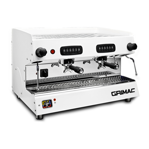
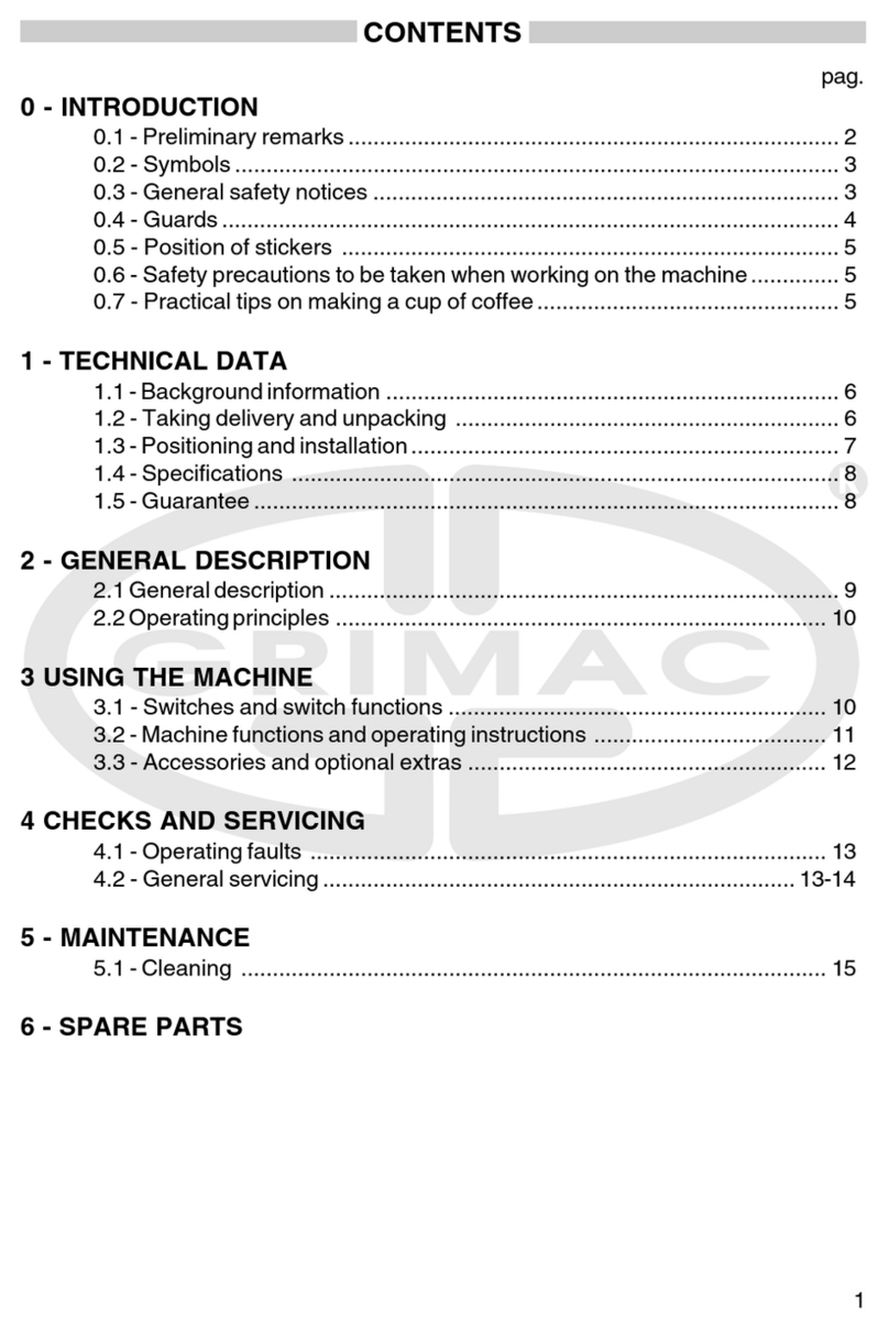
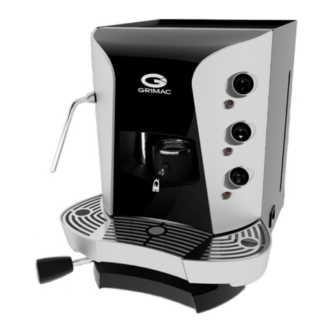
Grimac G 11 User manual

G 11
ISTRUZIONI PER L’USO
Leggere attentamente queste istruzioni d’uso
prima di utilizzare la macchina
Istruzioni originali
GEBRAUCHSANLEITUNGEN
Aufmerksam die folgenden Anleitungen vor
dem Gebrauch der Maschine lesen.
Übersetzung der
Originalanleitungen
OPERATING INSTRUCTIONS
Read these instructions carefully
before using the machine
Translates of the
original instrunctions
INSTRUCTIONS POUR L’EMPLOI
Lire attentivement ces instructions d’emploi
avant d’utiliser la machine.
Traduction des
Instructions Originales
INSTRUCCIONES PARA EL USO
Leer atentamente estas instrucciones de uso
ntes de usar la máquina.
Traducción de las
Instrucciones Originales
ITALIANOENGLISHFrANçAISE
DEuTScH
ESpAñOL

25
ENGLISH
Dear Customer, GRIMAC S.p.A. would like to thank you for your choice
and guarantees the highest quality of your purchase.

26
ENGLISH
INDEX
1 INTRODUCTION...................29
1.1 Constructor...........................29
1.2 Authorized personnel...........29
1.3 Manual structure..................29
1.3.1 Aim and contents.................29
1.3.2 Recipients...............................29
1.3.3 Storage...................................29
1.3.4 Signs used ..............................30
1.4 Warranty..............................30
2 APPLIANCE DESCRIPTION....31
2.1 Appliance use.......................31
2.2 Main components ................31
2.3 Equipment ...........................32
2.4 Technical specications........33
2.5 Control panel........................34
2.5.1 Push button version................34
2.5.2 Electronic version ...................35
3 SAFETY............................... 36
3.1 General Safety Rules ............36
3.2 Stop functions......................36
3.3 Identication........................37
4 HANDLING AND STORAGE.... 37
4.1 Packing ................................37
4.2 Transport and handling........37
4.3 Storage.................................37
5 INSTALLATION....................38
5.1 Assembly-Siting...................38
5.2 Packing disposal...................39
5.3 Water Network Connector....39
5.4 Electrical connection............39
6 FUNCTIONING.....................40
6.1 Switching on the Machine....40
6.2 Coee...................................41
6.2.1 Loading coee........................41
6.2.2 Dispensing coee
(key machine).........................41
6.2.3 Coee Brewing
(electronic machine)...............42
6.3 HotWater.............................42
6.3.1 Dispensation of hot water
(key machine).........................43
6.3.2 Hot water dispensing
(electronic machine)...............43
6.4 Steam...................................43
6.5 Cup warmer (optional).........44
6.6 Emergency conditions..........44
7 PROGRAMMING MENU
ELECTRONIC MACHINE...... 44

27
ENGLISH
8 CLEANING
AND MAINTENANCE ............45
8.1 Daily cleaning.......................45
8.2 Weekly cleaning...................45
8.3 Periodic Maintenance...........46
9 DEMOLITION ......................46
10 PROBLEMS REMEDIES .......46

28
ENGLISH

29
ENGLISH
1 INTRODUCTION
1.1 Constructor
Grimac S.p.A. - Via Morazzo, 2 - 40069
Zola Predosa (Bologna) - Italy
): +39 051 6167069
: +39 051 750996
*: info@grimac.net
: www.grimac.net
1.2 Authorized personnel
Two persons in charge with dierent duties can access the
machine.
OPERATOR
Person with adequate technical knowledge in preparing
products that the appliance uses to dispense coee, hot
water and steam according to current hygiene regulations.
After having gone through the manual, he can carry out the
following:
• usualinstallationproceduresoftheappliance;
• properproductdispensing;
• appliancecleaning.
SKILLED TECHNICIAN
Person who, after having gone through this manual, is
specialized in coee machine installation, use and mainte-
nance:
• hecancarryoutrepairsintheeventofseriousmalfunc-
tionsandknowsthisManualandallSafetyinformation;
• he can understand the Manual contents andinterpret
theDrawingsandDiagramscorrectly;
• heknowsthemainhygiene,personalprotection,tech-
nologicalandsafetystandards;
• heisspecicallyexperiencedincoeemachinemainte-
nance;
• he knows how to act in the event of an Emergency,
where to nd the personal protection means and how to
use them properly.
Unskilled persons are not allowed to use
the appliance.
1.3 Manual structure
The information in this Manual must be carefully read by the
Customer.
1.3.1 Aim and contents
This Manual aims to provide all information necessary for
coee machine installation, maintenance and use to the
Customer.
Before carrying out any intervention on
the appliance, the instructions in this man-
ual must be carefully read by the skilled
operators and the technicians
In case of doubts about the correct interpretation of instruc-
tions, please contact the Manufacturer to receive the neces-
saryexplanations.
It is forbidden to carry out any intervention
without having read and understood the
contents of this manual.
1.3.2 Recipients
This Manual is addressed to operators and skilled techni-
cians.
Operators are not allowed to carry out the operations of
skilled technicians.
The manufacturer cannot be held responsible for damage
caused by the non-observance of this ban.
This instruction manual is an integral part of the product
purchased and must always accompany it, even in case of it
being sold on to new owners.
1.3.3 Storage
The instruction manual must be stored in the immediate
vicinity of the appliance.
The following warnings are recommended in order to be
able to ensure the integrity and the legibility of this manual
over time.
• Avoiddamagetoallorpartofthemanualcontentswhile
consulting it.
• Donotabsolutelyremove,tearorre-writemanualparts.
• Store the manual in areas protected against humidity
and heat so that the manual quality and the legibility of
all its parts are not jeopardized.
30
ENGLISH
In the event the manual is damaged or lost,
immediately request another copy from
the manufacturer or the authorized dis-
tributor of the Country where the appli-
ance is used.
1.3.4 Signs used
GENERIC DANGER
This sign indicates a danger with even fatal haz-
ards for the User. In this case it is necessary to be
very careful and adopt all precautions to work in
a safe manner.
SHOCK HAZARD
This sign indicates to the sta concerned that the
operation described involves a shock hazard if it
is not carried out in compliance with the safety
rules.
WARNING
This sign indicates a warning or a remark con-
cerning key functions or useful information. The
textblocksindicatedbythissignmustbetaken
into the utmost consideration.
BAN
The presence of this sign shows the operations
that are to be absolutely avoided as they cause
danger for the User and the persons who work
nearby.
DO NOT EXTINGUISH FIRE WITH WATER
This sign indicates that re ghting with water or
any other substance containing water is not al-
lowed.
PERSONAL PROTECTION
The presence of this sign beside the description
requires the operator’s use of personal protection
as the injury hazard is implicit.
SKILLED TECHNICIAN
This sign indicates the actions that can be carried
out by skilled technical personnel only.
1.4 Warranty
Theguaranteeisvalidfor12monthsandextendstoallme-
chanical parts of the machine. It is annulled if the equipment
is not utilised in the appropriate way or is tampered with.
Parts damaged caused by the lack of cleaning and mainte-
nance and parts subject to wear are also not included in the
guarantee. The parts considered faulty by us will be replaced
free of charge.
Transport charges are to be met by the purchaser. The details
and the features indicated in this manual do not bind the
manufacturer, which reserves the right to carry out modi-
cations on its models at any time. Besides the manufacturer
shall not be liable for damage to persons or things result-
ing from the non-observance of the rules indicated in this
manual.

31
ENGLISH
2 APPLIANCE DESCRIPTION
2.1 Appliance use
Your purchased machine for professional use is suitable for
producing coee, hot water and steam.
2.2 Main components
The main components of the appliance are listed below:
1) Removable warming plate for saucersandcups
2) Cupwarmer (optional)
3) Control panel (seesection. 2.4)
4) Hot water wand
5) Brewgroup
6) Driptraywith grill
7) Steamwand
8) Feed cable
9) Mainselector switch
10) Steamwandrubberguard
11) Boiler resistanceONwarning light
12) Dispensing gauge(water network +pumppressure)
13) Boilerpressure gauge
14) Loadingwaterintotheboiler warning light
15) Steam dispensingwheel
16) Cupwarmer ON key (whereforeseen)
4
15
10
812
13 14
6
7
1
9
7
10
11
15
16
2 3 5

32
ENGLISH
2.3 Equipment
1) 2- cup lter holder
2) 1 -cup lter holder
3) 2- cup lter
4) 1- cup lter
5) Blind lter
6) Filter-fastening ring
7) Drain hose
8) Filling hose
9) Hose clamp
3
4
21
6
5
7
8
9

33
ENGLISH
2.4 Technical specications
The technical specications and features are listed below:
Model G 11
(2 groups)
G 11
(3 groups)
DimensionsLxPxA-(mm). 710x580x510 950x580x510
Weight (kg) (empty appliance). 55 67
Maxabsorbedpower(W). See technical detail plate on the bottom of the appliance
Working voltage (V). See technical detail plate on the bottom of the appliance
Working conditions. Temperature (Min. 10°C - 40°C) - Humidity (inferior to 90%)
Coee dispenser number 2 3
Boiler capacity (Litres) 10,4 19,7
Pump pressure + water network
pressure 9 bar 9 bar
Water network pressure 0 ÷ 4 bar 0 ÷ 4 bar
Sound pressure << 70 dB A
Safety devices Boiler safety valve
Note: The manufacturer reserves the right to make modications to the appliance without prior no-
tice.
Any modications and/or addition of accessories must be expressly approved and carried out by the
Manufacturer.
PL
A
PL
A

34
ENGLISH
2.5 Control panel
2.5.1 Push button version
G 11 (2 groups)
G 11 (3 groups)
Switch for dispensing
coee – left unit
Switch for dispensing
coee – right unit
Switch for dispensing
coee – right unit
Switch for dispensing
coee – left unit
Switch for dispensing
coee – central unit
Steam dispensing knob
Cup warmer ON/OFF
key (where foreseen)
Cup warmer ON/OFF
key (where foreseen)
Hot water
dispensing key
Hot water
dispensing key

35
ENGLISH
2.5.2 Electronic version
G 11 (2 groups)
G 11 (3 groups)
Steam dispensing knob Steam dispensing knob
Cup warmer ON/OFF
key (where foreseen)
Cup warmer ON/OFF
key (where foreseen)
Espresso coee
dispenser
Espresso coee
dispenser
Continuous and
programming of
dispensing coee
Continuous and
programming of
dispensing coee
Long coee
dispenser
Long coee
dispenser
Hot water
dispenser
Hot water
dispenser
Dispensation of 2 cups
of espresso coee
Dispensation of 2 cups
of espresso coee
Dispensation
of 2 cups of
long coee
Dispensation
of 2 cups of
long coee

36
ENGLISH
3 SAFETY
3.1 General Safety Rules
• The coee machine is for professional use.Technical
modications and any misuse are not allowed owing to
resulting risks! The appliance is not intended for use by
persons (children included) with reduced physical, men-
talorsensorycapabilitiesorlackofexperienceand/or
knowledge, unless they have been given supervision or
instruction concerning use of the appliance by a person
responsible for their safety.
• Connect the appliance to power supply in accordance
with the safety rules in force in the Country of use.
• Thesocket,towhichtheappliancehastobeconnected
to, must be:
- Conformtothepluginstalledontheappliance;
- Dimensioned to respect the data of the data name-
plate on the front of the machine at the side of the
selector switch.
- Connectedtoanecientgroundingplant;
- Connected to a plant with circuit breaker and magne-
tothermic switch.
• Thepowercordmustnot:
- Come in contact with any kind of liquid: shock and/or
rehazard;
- Be pressed and/or come in contact with sharp sur-
faces;
- Beusedtohandletheappliance;
- Be used when it is damaged. In case the power cord
is damaged, it must be replaced by the manufacturer
oritscustomerservice;
- Betouchedwithdamporwethands;
- Be coiled up while the appliance is working.
- Be tampered with.
• Itisforbidden:
- To install the appliance with dierent procedures
thantheonesdescribedinchapter5;
- To install the appliance in areas where a water jet
couldbeused;
- Tousetheapplianceintheproximityofammable
and/orexplosivesubstances;
- To leave plastic bags, polystyrene, nails, etc. within
children’sreachastheyarepotentialdangersources;
- Toleavechildrentoplayorstayintheproximityof
theappliance;
- To use spare parts not recommended by manufac-
turer;
- To carry out any technical modication to the appli-
ance;
- Todiptheapplianceintoanykindofliquid;
- Tocleantheappliancebymeansofwaterjet;
- To use the appliance in dierent ways than the ones
describedinthemanual;
- To use the appliance in modied psycho-physical
conditions; under the inuence of drugs, alcohol,
psychodrugs,etc;
- Toinstalltheapplianceuponotherappliances;
- Tousetheapplianceoutside;
- Theuseoftheapplianceinexplosiveoraggressive
ambience or with high concentration of powders or
oilysubstancesinsuspensionintheair;
- Theuseoftheapplianceinanambienceatrerisk;
- The use of the appliance to dispense substances that
arenotsuitabletoitsfeatures;
- To use the appliance with bare feet and wet hands.
• Before cleaningtheappliancebe surethattheplugis
disconnectedfromtheplugsocket;donotcleantheap-
pliance using fuel and/or solvents of any kind.
• Repairingmustsolelybecarriedoutbyaservicecentre
authorized by the manufacturer and/or by skilled and
trained personnel.
• Donotplacetheapplianceclosetoheatingequipments
(e.G. Stoves or heaters).
• In the event of re use carbon dioxide extinguishers
(co2).Donotusewaterorpowderextinguishers.
3.2 Stop functions
The appliance stop functions are operated by the main
switch.

37
ENGLISH
3.3 Identication
Each machine is identied by the technical data nameplate
and EC marking on the front of the machine.
The plate contains the essential data regarding installation,
moving, use, maintenance and demolition which can be
summarized as follows:
• Model
• Version
• immatriculation
• supplyvoltage(V)
• frequency(Hz)
• absorbedpower(W)
No plate on the appliance, including the
technical data one, must be removed, cov-
ered or damaged, especially the ones that
concerns safety.
4 HANDLING AND STORAGE
Only skilled technicians are responsible for
all actions described in chapter 4 even dur-
ing lifting and handling of packed and un-
packed appliances. According to the fea-
tures and weight of the product to handle,
they are in charge of the planning of all
operative procedures and the use of means
suitable to work in strict compliance with
the related current regulations.
4.1 Packing
The machine is shipped ready for use, packaged in a carton
box.Thecartonboxismadeofabaseandalid.
4.2 Transport and handling
Make sure nobody stands within the work-
ing area of the load lifting and handling
procedures and, in dicult conditions, pre-
dispose personnel in charge of checking the
movements to be made.
The appliance manual handling must be carried out by at
least two persons.
The machine must be shifted by lifting it from the ground.
Lift the packing and move it with care avoiding bumpy
ways and considering the overall dimensions and eventual
prongs.
Additional cuts on the packing are not al-
lowed.
Appliance damage during Transport and Handling are not
covered by WARRANTY.
Repairs or replacement of damaged parts are charged to the
Customer.
4.3 Storage
Before storing the appliance and by re-
starting it after a storage period, clean it
with care.
During storing procedures do not place
more than two appliances one upon the
other.
In case the appliance is not use for a long period, store it
according to the precautions concerning the storage place
and time:
• storetheapplianceinanenclosedspace;
• protectitagainstbumpsandstrains;
• protecttheappliance against humidityand hightem-
peratureranges;
• avoidappliancecontactwithcorrosivesubstances.

38
ENGLISH
5 INSTALLATION
All the operations described in section 5
must be performed exclusively by special-
ised technicians who shall organise all op-
erating sequences and employ suitable
means to ensure strict compliance with the
safety regulations in force.
The machine must be installed inside a lit, ventilated build-
ing with a solid paved, levelled (below 2° inclination) and
rmoor.
The appliance requires supervision and
must be installed in places where it can be
observed by trained personnel.
It is forbidden to install the machine in
places where it can be reached and touched
and/or operated by people who are not
those specied in section 1.2.
The machine must work in environments where tempera-
ture is between 10°C and 40°C.
5.1 Assembly-Siting
The operator must verify the following requirements:
• Thesiteshouldbesuitablypreparedfortheinstallation
ofthemachine;
• Thesurfaceonwhichthemachineisinstalledshouldbe
at,solidandrm;
• The location should be adequately lit, ventilated and
clean, and the power socket should be easily accessible.
Access to the machine should be kept clear
at all times, in order to allow the operator
to easily work on it and to immediately
leave the working area if required.
20 cm
The gure shows the spaces that are required for:
• Thepropercoolingofthemachineparts;
• Accesstoservicegroupsincaseofmachinemalfunction.
After placing the packaging container near the installation
site, proceed as follows:
While unpacking pay the utmost attention,
so as to avoid abrasions and/or cuts.
1) Removethestaplesthatkeepthepackagingclosed;
2) Openthecartonboxusingacuttertocutthetapethat
securestheapsofthebox;
3) Lift the machine and place it in the designated area.
Before operating the machine for the rst
time, it is necessary to carry out a thorough
cleaningof its parts. Forfurtherdetails,see
the related section.
Remove the upper cover to gain ac-
cess to the inside of the machine.
Remove the protective lms from all the machine sheets.
After removing the protective lms, reposition the parts on
the machine.
Warning: Before commissioning and using
the machine for the rst time, carry out
rinsing operations of the drip tray.

39
ENGLISH
5.2 Packing disposal
When opening the packing it is recommended to separate
the various material used and to dispose of them in compli-
ance with the current standards in the Country of destina-
tion.
It is recommended to store the packing for further handling
or transportation.
5.3 Water Network Connector
Warning: Connect the machine to a water
network that dispenses only clear and
fresh drinking water. See the “technical
data” table to check if the pressure of the
network is suitable.
The distance between the sources for elec-
trical connection and water connection
should respect the regulations in force at
the time of installation.
The water of the water network must be
softened by using an appropriate water
softener placed right before the machine
connection pipe. A failed or inadequate
water softening will not be covered by war-
ranty. To full these procedures, turn to a
specialised technician.
• Position the water softener underneath the machine
(not too far away).
• Connectthewatersoftenertothewaternetworkasper
the instructions and depending on the type of water sof-
tener.
• Connectthewatersoftenertothemachine.
• Loadwaterintothewatersoftener(remembertoopen
the water network tap before proceeding with loading
water into the water softener).
• Oncethewaterisloaded,opentheoutlettapofthewa-
ter softener.
5.4 Electrical connection
Such operation must be carried out in com-
pliance with the safety rules of the Country
of installation.
Before making the electrical connection ensure that the se-
lector switch is turned to the “0” position.
The electrical connection must be carried
out and under the responsibility of the
technician that carries out repairs.
The machine must be connected to the electrical installation
considering:
• thetechnicallawsandrulesinforceintheplaceatthe
timeofinstallation;
• thedatashownonthetechnicalspecicationplateon
the side of the machine.
The connection point of the electric socket
must be situated in a place that can be
reached easily by the user so that he could
quickly disconnect the appliance from the
power supply when necessary.
In case the power cord is damaged, contact the manufac-
turer or a skilled technician only for replacing it.
It is forbidden:
•touseextensioncordsofanysort;
•toreplacetheoriginalplug;
•touseadapters.
The machine is supplied with a three-pole feed cable
(phase/neutral/Earth) or a ve-pole cable (phase 1/phase 2/
phase 3/neutral/Earth) depending on the model.
Firstly, connect the cable to the machine utilising the ap-
propriate connector and then connect the machine to the
electrical mains circuit in either single-phase with the
three-pole cable or three-phase with the ve-pole cable.

40
ENGLISH
6 FUNCTIONING
Before proceeding with the start-up, you must check that all
parts are properly installed.
Check that:
• Thewatersupplytapisopen;
• Theoutlettapofthewatersoftenerisopen(andtheoper-
ation of loading the water softener has been carried out).
• Allthemachinepartsarecleanandworkingproperly;
• Checkthatthedriptrayemptiesandisinthecorrectpo-
sition.
• Checkthatthesteamdispensingknobsareclosed.
• Thatallofthebuttonsonthecontrolpanelare“OFF”.
6.1 Switching ON the Machine
Please refer to the whole section to learn more on how to op-
erate the machine.
In this case, let’s take the switching ON of the 2 unit machine
into consideration. Switching ON the 3 unit machine occurs
in the same way.
• Turntheswitchto«1»andwaitfortheboilertollup
(the warning light remains ON at the side of the selector
switch).
At the same time the warning light alongside the gauge
indicates the loading of the water into the boiler.
• On electronic machines the lling function features a
safety time after which all selections are disabled.
lfitisexceeded,llingstopsandtheeventissignalledby
the blinking of the LEDs in the push-button panel.
To reset the machine, switch it o and on again.
• Once the loading has nished, position the selector
switch to the “2” position and wait 30 minutes for the
machine to heat up.
During this period, you should operate the steam knobs
and the dispensing group buttons, for few seconds, to
eliminate any air bubbles.
• Checkthatthepressureontheappropriategaugedoes
notexceed0.8bar-1bar.Ifnecessary,adjustthepres-
sure as described in paragraph 5.3.
Note: before turning the machine ON for
the rst time or when using it after a pro-
longed period of inactivity, it is necessary
to ll and rinse the water network. Carry
out 3 rinsing cycles dispensing hot water
fromtherelativewand;fordispensinghot
water follow the procedure as indicated in
sections 6.3.1 and 6.3.2.

41
ENGLISH
6.2 Coee
On every Grimac appliance, the coee dispensing procedure
iseasyandquick;adeliciouscoeecanbetastedafterfew
steps.
Before dispensing coee, check all components are prop-
erly clean. Refer to paragraph 9 for the correct cleaning and
maintenance of the appliance. Refer to chapter 8 for the cor-
rect cleaning and maintenance of the machine.
6.2.1 Loading coee
The method for loading coee is the same for all machines.
Inthiscase,forexample,a2unitmachineisutilised.
Place a dose or ground coee in the lter.
Shake the coee a little in order to distribute it evenly and
press it slightly with the tamper.
If necessary, clean the edge or the lter to guarantee a bet-
ter sealing and a longer life to the undercup gasket.
Insert the lter holder and screw it
tightly in its seat.
Check that the lter holder and the
undercup gasket seat tightly.
.
Place 1 or 2 cups under the spout/s
dispenser/s, depending on the dos-
es and the lter holder utilised.
Warm cups avour a creamy cof-
fee.
6.2.2 Dispensing coee
(key machine)
After loading the lter holder, dispense the coee. For man-
ual machines, controlling the quantity of coee in a small
cup depends on the operator’s sensitivity.
Thisway,thepreferred amount of coeecanbe brewedeach
time.
Note: Each dispensing group has its own dis-
pensing control unit which must be managed
autonomously.
In this case, let’s take the dispensation of the single unit ma-
chine into consideration.
The dispensation of the other units happens identically.
Place the small cup under the dispensing spout.
Press the button above the group
to start brewing coee.
When the desired quantity of cof-
fee has been obtained, press the
switch again to stop the brewing.
Note:Inthis case, youcanadjustthe length
of the coee according to your customer’s
needandtothesizesofthesmallcup;ifthe
brewing is not stopped manually, the cof-
fee may spill out of the small cup.
When brewing ends, leave the lter holder in its seat until
thenexttimeyouuseit.
Before making coee again, release the lter holder from
the brew head and throw the grounds away into the knock
out drawer.
Empty the drip tray often and ensure that
it has been reinserted into the correct posi-
tion.

42
ENGLISH
6.2.3 Coee Brewing
(electronic machine)
After loading the lter holder, dispense the coee. In elec-
tronic machines, controlling the amount of coee brewed in
a small cup is performed with high precision in order to brew
the best quantity of coee at any given circumstance.
Note: Each dispensing group has its own dis-
pensing control unit which must be man-
aged autonomously. To program an elec-
tronic machine, refer to section 7.
In this case, let’s take the dispensation of the single unit ma-
chine into consideration.
The dispensation of the other units happens identically.
Place the small cup under the dispensing spout.
To dispense coee use the button
panel located above the dispens-
ing group.
In this case, press:
Tobrewanespressocoee;
Tobrewalongcoee;
To dispense 2 cups of espresso coee
To dispense 2 cups of long coee
To brew a manual coee dose.
The buttons and brew a pre-
set quantity of coee (the machine automatically stops
the brewing);thisquantityhas beenprogrammedbythe
manufacturer but can be modied by the user based on the
required parameters.
The button allows manual brewing. This way a vari-
ablequantityofcoeecanbebrewed;thebrewingmustbe
manually stopped by the user.
This button allows you to stop espresso coee and long cof-
fee dispensing at any moment.
When brewing ends, leave the lter holder in its seat until
thenexttimeyouuseit.
Before making coee again, release the lter holder from
the brew head and throw the grounds away into the knock
out drawer.
Empty the drip tray often and ensure that
it has been reinserted into the correct posi-
tion.
6.3 Hot Water
Danger of being burnt! At the start of the
brewing, short spurts of hot water may
come out.
Danger of being burned! The wand can
reach very high temperatures.
Before dispensing hot water, posi-
tion a container underneath the
hot water hose.
To better control the dispensing, you can put the container
close to the wand.
Note: the procedure for dispensing hot wa-
ter varies according to the machine that
you have chosen.
Note: It is recommended to dispense a
maximum quantity of water equal to a cup
of tea each time (about 200 cc) and wait
until the machine restores the right tem-
perature.

43
ENGLISH
6.3.1 Dispensation of hot water
(key machine)
After positioning the container,
push the hot water dispensing
switch.
The switch is positioned above the
hot water dispensation wand.
In this way hot water will start
coming out.
Keep pushing the switch until reaching the desired quantity.
6.3.2 Hot water dispensing
(electronic machine)
For electronic control single ma-
chines, dispensing hot water is set
by a button.
To dispense the set quantity of hot
water (timed command), push the
button.
The machine will automatically stop the dispensing once it
reaches the preset quantity.
The quantity is designated by the manufacturer but you can
reprogramme it any time according to your liking.
Note: The dispensing can be stopped any-
time by pressing the button again.
6.4 Steam
Danger of being burnt! At the start of the
dispensing, short spurts of hot water and/
or steam may come out.
Danger of being burnt! The wand can reach
extremely high temperatures. Use the rub-
ber guard to move.
Note: Before using the steam, we recom-
mend to dispense a little of it in a separate
container to drain the condensed water
from the wand.
Place a container under the steam
wand.
After placing the container, you
have to open the steam knob by
turning the knob counterclock-
wise.
This way, the steam is dispensed
by the machine.
To stop the steam dispensing, close the steam knob by turn-
ing the knob clockwise.
After the steam has been dispensed, remove the container.
Direct the steam wand on the grill and slightly open the steam
knob;theinternalpartofthesteamwandiscleanedbydis-
pensing some steam.
With a damp cloth, immediately wipe the surface of the
steam wand for any traces of milk or other substances.
Other manuals for G 11
1
Table of contents
Other Grimac Coffee Maker manuals

Grimac
Grimac OPALE User manual

Grimac
Grimac Espressione BABY GRACE PG User manual

Grimac
Grimac DADA VAPOR DOPPIA User manual

Grimac
Grimac Ambra User manual

Grimac
Grimac TWENTY Manual

Grimac
Grimac TWENTY Series PUL 2 Manual

Grimac
Grimac TERRY TECH User manual

Grimac
Grimac G 11 User manual

Grimac
Grimac TERRY OPALE Capsule User manual

Grimac
Grimac Minigrimac User manual