Grizzly G4000 User manual

99''''XX1199''''MMEETTAALLLLAATTHHEE
MMOODDEELLGG44000000
IINNSSTTRRUUCCTTIIOONNMMAANNUUAALL
COPYRIGHT © 1999 BY GRIZZLY INDUSTRIAL, INC.
WWAARRNNIINNGG::NNOOPPOORRTTIIOONNOOFFTTHHIISSMMAANNUUAALLMMAAYYBBEERREEPPRROODDUUCCEEDDIINNAANNYYSSHHAAPPEE
OORRFFOORRMMWWIITTHHOOUUTTTTHHEEWWRRIITTTTEENNAAPPPPRROOVVAALLOOFFGGRRIIZZZZLLYYIINNDDUUSSTTRRIIAALL,,IINNCC..
REVISED OCTOBER, 1999 PRINTED IN U.S.A.

G4000 9'' x 19'' Lathe -1-
TTaabblleeOOffCCoonntteennttss
PPAAGGEE
11..SSAAFFEETTYY
SAFETY RULES FOR POWER TOOLS ..........................................................2-3
ADDITIONAL SAFETY INSTRUCTIONS FOR METAL LATHES ........................4
22..CCIIRRCCUUIITTRREEQQUUIIRREEMMEENNTTSS
110V OPERATION ..............................................................................................5
EXTENSION CORDS ..........................................................................................5
GROUNDING ......................................................................................................5
33..IINNTTRROODDUUCCTTIIOONN
COMMENTARY....................................................................................................6
UNPACKING ........................................................................................................7
PIECE INVENTORY ............................................................................................7
CLEAN UP............................................................................................................8
SITE CONSIDERATIONS ....................................................................................8
44..AASSSSEEMMBBLLYY&&SSEETTUUPP
MOUNTING ..........................................................................................................9
LUBRICATION ....................................................................................................9
CHUCKS ........................................................................................................9-10
LIVE CENTER....................................................................................................10
STEADY REST ..................................................................................................11
FOLLOW REST..................................................................................................11
55..CCOONNTTRROOLLSS
SPINDLE SPEEDS ............................................................................................12
FEED RATE ......................................................................................................13
CARRIAGE CONTROLS ..............................................................................14-16
TAILSTOCK CONTROLS ..................................................................................16
TEST RUN..........................................................................................................17
66..AADDJJUUSSTTMMEENNTTSS
SPINDLE RPM ..................................................................................................18
GIBS..............................................................................................................18-19
STEADY REST/FOLLOW REST........................................................................19
CHUCK RUNOUT ........................................................................................20-21
TAILSTOCK ..................................................................................................21-22
THREAD CUTTING............................................................................................23
77..MMAAIINNTTEENNAANNCCEE
LUBRICATION ..............................................................................................24-25
BEARING PRELOAD ........................................................................................25
88..CCLLOOSSUURREE................................................................................................................26
MACHINE DATA ................................................................................................................27
BELT CONFIGURATION CHART ......................................................................................28
STOCK RPM CHART ........................................................................................................29
PARTS BREAKDOWN AND PARTS LISTS ................................................................30-53
WARRANTY AND RETURNS ............................................................................................54

-2- G4000 9'' x 19'' Lathe
SSaaffeettyyIInnssttrruuccttiioonnssFFoorrPPoowweerrTToooollss
SSEECCTTIIOONN11::SSAAFFEETTYY
55..KKEEEEPPCCHHIILLDDRREENNAANNDDVVIISSIITTOORRSS
AAWWAAYY. All children and visitors should be
kept a safe distance from work area.
66..MMAAKKEEWWOORRKKSSHHOOPPCCHHIILLDDPPRROOOOFFwith
padlocks, master switches, or by removing
starter keys.
77..DDOONN’’TTFFOORRCCEETTOOOOLL. It will do the job
better and safer at the rate for which it was
designed.
88..UUSSEERRIIGGHHTTTTOOOOLL..Don’t force tool or
attachment to do a job for which it was not
designed.
11..KKEEEEPPGGUUAARRDDSSIINNPPLLAACCEEand in working
order.
22..RREEMMOOVVEEAADDJJUUSSTTIINNGGKKEEYYSSAANNDD
WWRREENNCCHHEESS. Develop a habit of checking
to see that keys and adjusting wrenches
are removed from tool before turning on..
33..KKEEEEPPWWOORRKKAARREEAACCLLEEAANN. Cluttered
areas and benches invite accidents.
44..DDOONN’’TTUUSSEEIINNDDAANNGGEERROOUUSSEENNVVIIRROONN--
MMEENNTT. Don’t use power tools in damp or
wet locations, or where any flammable or
noxious fumes may exist. Keep work area
well lighted.
FFoorrYYoouurrOOwwnnSSaaffeettyyRReeaaddIInnssttrruuccttiioonn
MMaannuuaallBBeeffoorreeOOppeerraattiinnggTThhiissEEqquuiippmmeenntt
IInnddiiccaatteessaanniimmmmiinneennttllyyhhaazzaarrddoouussssiittuuaattiioonnwwhhiicchh,,iiffnnoott
aavvooiiddeedd,,WWIILLLLrreessuullttiinnddeeaatthhoorrsseerriioouussiinnjjuurryy..
IInnddiiccaatteessaappootteennttiiaallllyyhhaazzaarrddoouussssiittuuaattiioonnwwhhiicchh,,iiffnnoott
aavvooiiddeedd,,CCOOUULLDDrreessuullttiinnddeeaatthhoorrsseerriioouussiinnjjuurryy..
IInnddiiccaatteessaappootteennttiiaallllyyhhaazzaarrddoouussssiittuuaattiioonnwwhhiicchh,,iiffnnoott
aavvooiiddeedd,,MMAAYYrreessuullttiinnmmiinnoorroorrmmooddeerraatteeiinnjjuurryy..IIttmmaayyaallssoo
bbeeuusseeddttooaalleerrttaaggaaiinnssttuunnssaaffeepprraaccttiicceess..
TThhiissssyymmbboolliissuusseeddttooaalleerrtttthheeuusseerrttoouusseeffuulliinnffoorrmmaattiioonn
aabboouuttpprrooppeerrooppeerraattiioonnoofftthheeeeqquuiippmmeenntt..
TThheeppuurrppoosseeooffssaaffeettyyssyymmbboollssiissttooaattttrraaccttyyoouurraatttteennttiioonnttooppoossssiibblleehhaazzaarrddoouussccoonnddiittiioonnss..
TThhiissmmaannuuaalluusseessaasseerriieessooffssyymmbboollssaannddssiiggnnaallwwoorrddsswwhhiicchhaarreeiinntteennddeeddttooccoonnvveeyytthheelleevveell
ooffiimmppoorrttaanncceeoofftthheessaaffeettyymmeessssaaggeess..TThheepprrooggrreessssiioonnooffssyymmbboollssiissddeessccrriibbeeddbbeellooww..
RReemmeemmbbeerrtthhaattssaaffeettyymmeessssaaggeessbbyytthheemmsseellvveessddoonnootteelliimmiinnaatteeddaannggeerraannddaarreennoottaassuubbssttii--
ttuutteeffoorrpprrooppeerraacccciiddeennttpprreevveennttiioonnmmeeaassuurreess..
NNOOTTIICCEE

G4000 9'' x 19'' Lathe -3-
99..UUSSEEPPRROOPPEERREEXXTTEENNSSIIOONNCCOORRDD. Make
sure your extension cord is in good condi-
tion. Conductor size should be in accor-
dance with the chart below. The amperage
rating should be listed on the motor or tool
nameplate. An undersized cord will cause a
drop in line voltage resulting in loss of
power and overheating. Your extension
cord must also contain a ground wire and
plug pin. Always repair or replace exten-
sion cords if they become damaged.
Minimum Gauge for Extension Cords
1100..WWEEAARRPPRROOPPEERRAAPPPPAARREELL..Do not wear
loose clothing, gloves, neckties, rings,
bracelets, or other jewelry which may get
caught in moving parts. Non-slip footwear
is recommended. Wear protective hair cov-
ering to contain long hair.
1111..AALLWWAAYYSSUUSSEESSAAFFEETTYYGGLLAASSSSEESS..Also
use face or dust mask if cutting operation is
dusty. Everyday eyeglasses only have
impact resistant lenses, they are NOT safe-
ty glasses.
1122..SSEECCUURREEWWOORRKK..Use clamps or a vise to
hold work when practical. It’s safer than
using your hand and frees both hands to
operate tool.
LLEENNGGTTHH
AAMMPPRRAATTIINNGG2255fftt5500fftt110000fftt
0-6 18 16 16
7-10 18 16 14
11-12 16 16 14
13-16 14 12 12
17-20 12 12 10
21-30 10 10 No
SSaaffeettyyIInnssttrruuccttiioonnssFFoorrPPoowweerrTToooollss
1133..DDOONN’’TTOOVVEERRRREEAACCHH..Keep proper foot-
ing and balance at all times.
1144..MMAAIINNTTAAIINNTTOOOOLLSSWWIITTHHCCAARREE..Keep
tools sharp and clean for best and safest
performance. Follow instructions for lubri-
cating and changing accessories.
1155..DDIISSCCOONNNNEECCTTTTOOOOLLSSbefore servicing
and changing accessories, such as blades,
bits, cutters, and the like.
1166..RREEDDUUCCEETTHHEERRIISSKKOOFFUUNNIINNTTEENNTTIIOONN--
AALLSSTTAARRTTIINNGG..Make sure switch is in off
position before plugging in.
1177..UUSSEERREECCOOMMMMEENNDDEEDDAACCCCEESSSSOORRIIEESS..
Consult the owner’s manual for recom-
mended accessories. The use of improper
accessories may cause risk of injury.
1188..CCHHEECCKKDDAAMMAAGGEEDDPPAARRTTSS..Before fur-
ther use of the tool, a guard or other part
that is damaged should be carefully
checked to determine that it will operate
properly and perform its intended function.
Check for alignment of moving parts, bind-
ing of moving parts, breakage of parts,
mounting, and any other conditions that
may affect its operation. A guard or other
part that is damaged should be properly
repaired or replaced.
1199..NNEEVVEERRLLEEAAVVEETTOOOOLLRRUUNNNNIINNGGUUNNAATT--
TTEENNDDEEDD..TTUURRNNPPOOWWEERROOFFFF..Don’t
leave tool until it comes to a complete stop.

-4- G4000 9'' x 19'' Lathe
AAddddiittiioonnaallSSaaffeettyyIInnssttrruuccttiioonnssFFoorrTThheeLLaatthhee
LLiikkeeaallllppoowweerrttoooollss,,tthheerreeiissddaannggeerraassssoo--
cciiaatteeddwwiitthhtthheeMMooddeellGG44000000MMeettaallLLaatthhee..
AAcccciiddeennttssaarreeffrreeqquueennttllyyccaauusseeddbbyyllaacckkooff
ffaammiilliiaarriittyyoorrffaaiilluurreettooppaayyaatttteennttiioonn..UUssee
tthhiissttoooollwwiitthhrreessppeeccttaannddccaauuttiioonnttoolleesssseenn
tthheeppoossssiibbiilliittyyooffooppeerraattoorriinnjjuurryy..IIffnnoorrmmaall
ssaaffeettyypprreeccaauuttiioonnssaarreeoovveerrllooookkeeddoorr
iiggnnoorreeddsseerriioouussppeerrssoonnaalliinnjjuurryymmaayyooccccuurr..
11..MMAAKKEESSUURREEAALLLLGGUUAARRDDSSare in place
and that the lathe sits on a flat, stable sur-
face.
22..BBEEFFOORREESSTTAARRTTIINNGGTTHHEEMMAACCHHIINNEEbe
certain the workpiece has been properly
engaged in the chuck and tailstock center (if
in use) and that there is adequate clearance
for full rotation.
33..AADDJJUUSSTTTTOOOOLLHHOOLLDDEERRto provide proper
support for the turning tool you will be using.
Test tool holder clearance by rotating work-
piece by hand before turning lathe on.
44..SSEELLEECCTTTTHHEETTUURRNNIINNGGSSPPEEEEDDwhich is
appropriate for the type of work and the type
of material. Allow the lathe to gain its full
speed before beginning turning.
55..NNEEVVEERRCCHHAANNGGEEFFEEEEDDRRAATTEEor spindle
speeds while the lathe is turning.
66..NNEEVVEERRRREEVVEERRSSEEMMOOTTOORRDDIIRREECCTTIIOONN
while the lathe is running.
77..DDOONNOOTTSSTTOOPPLLAATTHHEEUUSSIINNGGYYOOUURR
HHAANNDDagainst the workpiece.
88..DDOONNOOTTLLEEAAVVEELLAATTHHEERRUUNNNNIINNGGUUNNAATT--
TTEENNDDEEDDfor any reason.
99..NNEEVVEERROOPPEERRAATTEETTHHEELLAATTHHEEWWIITTHH
DDAAMMAAGGEEDDOORRWWOORRNNPPAARRTTSS..Maintain
your lathe in proper working condition.
Perform routine inspections and mainte-
nance promptly when called for. Put away
adjustment tools after use.
1100..MMAAKKEESSUURREEYYOOUURRMMEETTAALLLLAATTHHEEIISS
TTUURRNNEEDDOOFFFF, disconnected from its power
source and all moving parts have come to a
complete stop before starting any inspection,
adjustment, or maintenance procedure.
1111..KKEEEEPPLLOOOOSSEECCLLOOTTHHIINNGGAARRTTIICCLLEESSsuch
as sleeves, belts or jewelry items away from
the lathe spindle.
1122..AALLWWAAYYSSUUSSEETTHHEEPPRROOPPEERRCCUUTTTTIINNGG
TTOOOOLLSSfor the material you are turning,
make certain they are sharp and that they
are held firmly in the tool holder.
1133..AALLWWAAYYSSPPLLAACCEEAABBOOAARRDDOORRPPIIEECCEEOOFF
PPLLYYWWOOOODDAACCRROOSSSSTTHHEEBBEEDDWWAAYYwhen
removing or installing chucks to avoid the
possibility of a finger pinch point occurring
between a loose chuck and the edges of the
bedway.
NNoolliissttooffssaaffeettyygguuiiddeelliinneessccaannbbeeccoommpplleettee..
EEvveerryysshhooppeennvviirroonnmmeennttiissddiiffffeerreenntt..AAllwwaayyss
ccoonnssiiddeerrssaaffeettyyffiirrsstt,,aassiittaapppplliieessttooyyoouurr
iinnddiivviidduuaallwwoorrkkiinnggccoonnddiittiioonnss..UUsseetthhiissaanndd
ootthheerrmmaacchhiinneerryywwiitthhccaauuttiioonnaannddrreessppeecctt..
FFaaiilluurreettooddoossooccoouullddrreessuullttiinnsseerriioouussppeerr--
ssoonnaalliinnjjuurryy,,ddaammaaggeettooeeqquuiippmmeennttoorrppoooorr
wwoorrkkrreessuullttss..

G4000 9'' x 19'' Lathe -5-
111100VVOOppeerraattiioonn
SSEECCTTIIOONN22::CCIIRRCCUUIITTRREEQQUUIIRREEMMEENNTTSS
FFiigguurree11..Typical 110V plug and outlet.
Grounded Outlet Box
Current
Carrying
Prongs
Grounding Blade Is
Longest Of the Three Blades
GGrroouunnddiinngg
In the event of an electrical short, grounding
reduces the risk of electric shock by providing a
path of least resistance to disperse electric cur-
rent. This tool is equipped with a power cord hav-
ing an equipment-grounding conductor. SSeeee
FFiigguurree11..The outlet must be properly installed
and grounded in accordance with all local codes
and ordinances.
The Model G4000 is wired for 110 volt, single
phase operation only. The 3⁄4 HP motor will safely
draw 12 amps at 110V. A 15-amp fuse or circuit
breaker should be used when connecting this
metal lathe. Circuits rated any higher are not ade-
quate to protect the motor.
If you operate this lathe on any circuit that is
already close to its capacity, it might blow a fuse
or trip a circuit breaker. However, if an unusual
load does not exist and a power failure still
occurs, contact a qualified electrician or our ser-
vice department.
Equipment returned to us for service that shows
evidence of being over-fused will be repaired or
replaced totally at the customer’s expense,
regardless of the present warranty status.
If you find it necessary to use an extension cord
with the Model G4000, make sure the cord is
rated Hard Service (grade S) or better. Refer to
the chart in the standard safety instructions to
determine the minimum gauge for the extension
cord. The extension cord must also contain a
ground wire and plug pin. Always repair or
replace extension cords when they become worn
or damaged.
EExxtteennssiioonnCCoorrddss
TThhiisseeqquuiippmmeennttmmuussttbbeeggrroouunnddeedd..VVeerriiffyy
tthhaattaannyyeexxiissttiinnggeelleeccttrriiccaalloouuttlleettaannddcciirrccuuiitt
yyoouuiinntteennddttoopplluuggiinnttooiissaaccttuuaallllyyggrroouunndd--
eedd..IIffiittiissnnoott,,iittwwiillllbbeenneecceessssaarryyttoorruunnaa
sseeppaarraattee1122AA..WW..GG..ccooppppeerrggrroouunnddiinnggwwiirree
ffrroommtthheeoouuttlleettttooaakknnoowwnnggrroouunndd..UUnnddeerr
nnoocciirrccuummssttaanncceesssshhoouullddtthheeggrroouunnddiinnggppiinn
ffrroommaannyytthhrreeee--pprroonnggeeddpplluuggbbeerreemmoovveedd..
SSeerriioouussiinnjjuurryymmaayyooccccuurr..

-6- G4000 9'' x 19'' Lathe
CCoommmmeennttaarryy
We are proud to offer the Grizzly Model G4000
9" x 19" Metal Lathe. The Model G4000 is part of
a growing Grizzly family of fine metalworking
machinery. When used according to the guide-
lines set forth in this manual, you can expect
years of trouble-free, enjoyable operation and
proof of Grizzly’s commitment to customer satis-
faction.
The Model G4000 is a precision metalworking
lathe. It features cast iron construction, 19" V-
bed, a speed range of 130-2,000 RPM, 6-speed
gearbox and a complete electrical package. The
electrical package consists of a, 3⁄4 H.P., 110V
motor, mechanical forward and reverse switch
and cord set. We also offer many accessories for
this lathe. Please refer to the latest Grizzly cata-
log for prices and information.
We are also pleased to provide this instructional
manual with the Model G4000 Lathe. This manu-
al was written to guide you through assembly,
review safety considerations and cover basic
operating procedures. It represents our latest
effort to produce the best documentation possi-
ble. If you have any constructive criticisms or
comments you feel we should include in our next
printing, please write us at the address below.
Grizzly Industrial, Inc.
C/O Technical Documentation
P.O. Box 2069
Bellingham, WA 98227-2069
Most importantly, we stand behind our machines.
If you have any service questions or parts
requests, please call or write us at the location
listed below.
Grizzly Industrial, Inc.
2406 Reach Road
Williamsport, PA 17701
Phone: (570) 326-3806
Fax: (800) 438-5901
E-Mail: [email protected]
Web Site: http://www.grizzly.com
The specifications, drawings, and photographs
illustrated in this manual represent the Model
G4000 as supplied when the manual was pre-
pared. However, owing to Grizzly’s policy of con-
tinuous improvement, changes may be made at
any time with no obligation on the part of Grizzly.
Whenever possible, though, we send manual
updates to all owners of a particular tool or
machine. Should you receive one, we urge you to
insert the new information with the old and keep
it for reference.
TTooooppeerraatteetthhiiss,,oorraannyyppoowweerrttooooll,,ssaaffeellyy
aannddeeffffiicciieennttllyy,,iittiisseesssseennttiiaallttoobbeeccoommeeaass
ffaammiilliiaarrwwiitthhiittsscchhaarraacctteerriissttiiccssaassppoossssiibbllee..
TThheettiimmeeyyoouuiinnvveessttbbeeffoorreeyyoouubbeeggiinnttoouussee
yyoouurrMMooddeellGG44000000wwiillllbbeettiimmeewweellllssppeenntt..
DDOONNOOTTooppeerraatteetthhiissmmaacchhiinneeuunnttiillyyoouuaarree
ccoommpplleetteellyyffaammiilliiaarrwwiitthhtthheeccoonntteennttssoofftthhiiss
mmaannuuaall..MMaakkeessuurreeyyoouurreeaaddaanndduunnddeerr--
ssttaannddaalllloofftthheessaaffeettyypprroocceedduurreess..IIffyyoouuddoo
nnoottuunnddeerrssttaannddssoommeetthhiinngg,,DDOONNOOTTooppeerraattee
tthheemmaacchhiinnee..
SSEECCTTIIOONN33::IINNTTRROODDUUCCTTIIOONN

G4000 9'' x 19'' Lathe -7-
UUnnppaacckkiinngg
This Metal Lathe is shipped from the manufactur-
er in a carefully packed carton. If you discover the
machine is damaged after you’ve signed for deliv-
ery, and the truck and driver are gone, you will
need to file a freight claim with the carrier. Save
the containers and all packing materials for pos-
sible inspection by the carrier or its agent.
Without the packing materials, filing a freight
claim can be difficult. If you need assistance
determining whether you need to file a freight
claim, or with the procedure to file one, please
contact our Customer Service.
When you are completely satisfied with the con-
dition of your shipment, you should inventory its
parts.
The G4000 is a heavy machine (300 lbs. ship-
ping weight). DO NOT over-exert yourself
while unpacking or moving your machine – get
assistance. In the event that your Metal Lathe
must be moved up or down a flight of stairs, be
sure that the stairs are capable of supporting
the combined weight of people and the
machine. SSeerriioouussppeerrssoonnaalliinnjjuurryymmaayy
ooccccuurr..
PPiieecceeIInnvveennttoorryy
The Model G4000 is, for the most part, pre-
assembled at the factory. Inside the crate you’ll
find:
•The Model G4000 Metal Lathe
•4" 3-jaw Chuck
•7" 4-jaw Chuck
•Face Plate
•Steady Rest
•Following Rest
•4-Way Tool Post
•C-Type Tool Post
•Toolbox
•Metric Allen®Wrenches
•8-10mm Combination wrench
•Regular Screwdriver
•Phillips®Screwdriver
•Oil can
•30T Gear (2)
•36T Gear
•42T Gear
•45T Gear
•80T Gear (2)
•Chuck wrenches (2)
•Chuck Removal Bars (2)
•Reverse Jaws for the 3-Jaw Chuck
•Dead Centers - MT #2, MT #3
•Live Center - MT #3
In the event that any non-proprietary parts are
missing (e.g. a nut or a washer), we would be
glad to replace them, or, for the sake of expedi-
ency, replacements can be obtained at your local
hardware store.

-8- G4000 9'' x 19'' Lathe
SSiitteeCCoonnssiiddeerraattiioonnss
11..FFlloooorrLLooaadd::The Model G4000 can be
mounted on your existing workbench or on
an optional cabinet stand which is listed in
our current Grizzly catalog. If you choose to
use the stand, you will find the holes for bolt-
ing the G4000 to the stand are already in
place. If you are using your own bench,
ensure that it is strong enough to handle the
G4000 lathe. Keep in mind, whichever way
you choose to mount the lathe, it’s essential
that the mounting surface be perfectly flat.
Use an accurate carpenter’s level to ensure
that your bench is properly leveled.
22..WWoorrkkiinnggCClleeaarraanncceess::Consider existing and
anticipated needs, size of material to be
processed through each machine, and
space for auxiliary stands, work tables or
other machinery when establishing a loca-
tion for your lathe.
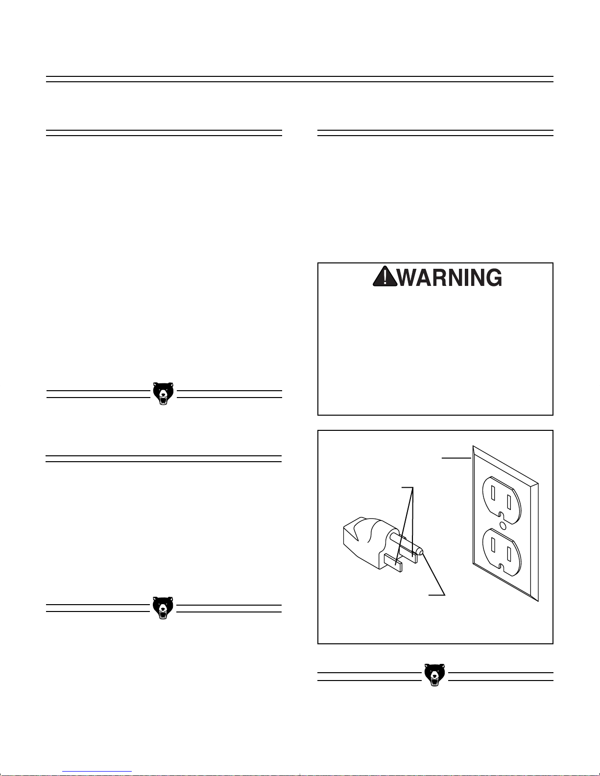
33..LLiigghhttiinnggaannddOOuuttlleettss::Lighting should be
bright enough to eliminate shadow and pre-
vent eye strain. Electrical circuits should be
dedicated or large enough to handle amper-
age requirements. Outlets should be located
near each machine so power or extension
cords are clear of high-traffic areas. Observe
local electrical codes for proper installation
of new lighting, outlets, or circuits.
CClleeaannUUpp
The unpainted surfaces are coated with a waxy
oil to protect them from corrosion during ship-
ment. Remove this protective coating with a sol-
vent cleaner or citrus-based degreaser. Avoid
chlorine-based solvents as they may damage
painted surfaces should they come in contact.
Always follow the usage instructions on the prod-
uct you choose for clean up.
MMaannyyoofftthheessoollvveennttssccoommmmoonnllyyuusseeddttoo
cclleeaannmmaacchhiinneerryyccaannbbeehhiigghhllyyffllaammmmaabbllee,,
aannddttooxxiiccwwhheenniinnhhaalleeddoorriinnggeesstteedd..AAllwwaayyss
wwoorrkkiinnwweellll--vveennttiillaatteeddaarreeaassffaarrffrroomm
ppootteennttiiaalliiggnniittiioonnssoouurrcceesswwhheennddeeaalliinngg
wwiitthhssoollvveennttss..UUsseeccaarreewwhheennddiissppoossiinnggooff
wwaasstteerraaggssaannddttoowweellssttoobbeessuurreetthheeyyddoo
nnoottccrreeaatteeffiirreeoorreennvviirroonnmmeennttaallhhaazzaarrddss..
KKeeeeppcchhiillddrreennaannddaanniimmaallssssaaffeellyyaawwaayy
wwhheenncclleeaanniinnggaannddaasssseemmbblliinnggtthhiiss
mmaacchhiinnee..
DDoonnoottuusseeggaassoolliinneeoorrootthheerrppeettrroolleeuumm--
bbaasseeddssoollvveennttssttoorreemmoovveetthhiisspprrootteeccttiivvee
ccooaattiinngg..TThheesseepprroodduuccttssggeenneerraallllyyhhaavveellooww
ffllaasshhppooiinnttsswwhhiicchhmmaakkeesstthheemmeexxttrreemmeellyy
ffllaammmmaabbllee..AArriisskkooffeexxpplloossiioonnaannddbbuurrnniinngg
eexxiissttssiifftthheesseepprroodduuccttssaarreeuusseedd..SSeerriioouuss
ppeerrssoonnaalliinnjjuurryymmaayyooccccuurr..
AAllllddiiee--ccuuttmmeettaallppaarrttsshhaavveeaasshhaarrppeeddggee
((ccaalllleedd““ffllaasshhiinngg””))oonntthheemmaafftteerrtthheeyyaarree
ffoorrmmeedd..TThhiissiissggeenneerraallllyyrreemmoovveeddaatttthhee
ffaaccttoorryy..SSoommeettiimmeessaabbiittooffffllaasshhiinnggmmiigghhtt
eessccaappeeiinnssppeeccttiioonn,,aannddtthheesshhaarrppeeddggeemmaayy
ccaauusseeccuuttssoorrllaacceerraattiioonnsswwhheennhhaannddlleedd..
PPlleeaasseeeexxaammiinneetthheeeeddggeessooffaallllddiiee--ccuutt
mmeettaallppaarrttssaannddffiilleeoorrssaannddtthheeeeddggeettoo
rreemmoovveetthheeffllaasshhiinnggbbeeffoorreehhaannddlliinngg..
MMaakkeeyyoouurrsshhoopp““cchhiillddssaaffee””..EEnnssuurreetthhaatt
yyoouurrwwoorrkkppllaacceeiissiinnaacccceessssiibblleettooyyoouunngg--
sstteerrssbbyycclloossiinnggaannddlloocckkiinnggaalllleennttrraanncceess
wwhheennyyoouuaarreeaawwaayy..NNeevveerraalllloowwvviissiittoorrssiinn
yyoouurrsshhooppwwhheennaasssseemmbblliinngg,,aaddjjuussttiinnggoorr
ooppeerraattiinnggeeqquuiippmmeenntt..

G4000 9'' x 19'' Lathe -9-
CChhuucckkss
The Model G4000 Metal Lathe comes equipped
with a 4'' 3-jaw chuck (already installed), a 7'' 4-
jaw chuck and a face plate.
The 3-jaw chuck is a scroll-type chuck, meaning
that all three jaws move in unison when adjust-
ments are made. The 4-jaw chuck, on the other
hand, features independent jaws. The 4-jaw
chuck is used for square or unevenly-shaped
stock.
The 3 and 4-jaw chucks have a setscrew in the
hub of the back plate. FFiigguurree22..This setscrew
prevents the chucks from unscrewing when rotat-
ing the lathe in the reverse direction. Prior to
removing the chuck, loosen the setscrew in the
hub of the back plate.
FFiigguurree22..Typical chuck mounting.
MMoouunnttiinngg
This lathe model should be securely mounted to
a stand or benchtop. An accessory stand is avail-
able from Grizzly, please see our current catalog
for pricing. There are two holes at each end of the
lathe base which can be used to secure machine
to the base.
The lathe does not require a great deal of assem-
bly. This section details the installation of the var-
ious accessory holding devices. The following
section will familiarize you with the controls for
your new lathe. After you have completed both of
these sections we will do a test run of the
machine. Do not attempt a test run until you have
become familiar with both of these sections.
SSEECCTTIIOONN44::AASSSSEEMMBBLLYY&&SSEETTUUPP
DDOONNOOTTaatttteemmppttttoossttaarrtttthhiissmmaacchhiinneeuunnttiill
yyoouuhhaavveeccoommpplleetteeddaalllloofftthheeaasssseemmbbllyyaanndd
ccoonnttrroollffaammiilliiaarriizzaattiioonnsstteeppss..WWhheennppeerrffoorrmm--
iinnggtthheeaasssseemmbbllyysstteeppss,,eennssuurreetthhaatttthhee
sswwiittcchhiissooffffaannddtthheeppoowweerriissddiissccoonnnneecctteedd..
FFaaiilluurreettooccoommppllyywwiitthhtthhiissccoouullddccaauussee
iinnaaddvveerrtteennttssttaarrttiinnggoofftthheemmaacchhiinneewwhhiicchh
ccaannrreessuullttiinnsseerriioouussooppeerraattoorriinnjjuurryy..
LLuubbrriiccaattiioonn
The G4000 is shipped from the factory pre-lubri-
cated. However, it is recommended that you go
through the entire lubrication sequence before
operating the machine. Review SSeeccttiioonn77::
MMaaiinntteennaanncceefor lubrication instructions.
LLuubbrriiccaattiioonnmmuussttbbeeccoommpplleetteeddbbeeffoorreeyyoouu
ssttaarrttyyoouurrnneewwllaatthhee..
Setscrew
AALLWWAAYYSSppllaacceeaappiieecceeooffppllyywwooooddoovveerrtthhee
wwaayyssoofftthheellaatthheebbeeffoorreerreemmoovviinnggoorr
iinnssttaalllliinnggaacchhuucckk..TThhiisshheellppssiinnpprroovviiddiinnggaa
ffllaattssuurrffaacceeffoorrtthheecchhuucckkttoollaannddoonn,,tthheerree--
bbyyaavvooiiddiinnggaappootteennttiiaallffiinnggeerrppiinncchhssiittuuaa--
ttiioonn..

-10- G4000 9'' x 19'' Lathe
FFiigguurree33..Chuck removal bars in place.
Use the chuck removal bars supplied to remove
the 3 or 4-jaw chucks. FFiigguurree33..Use one bar to
hold the spindle stationary, the other to unscrew
the chuck. Turn the chuck counter-clockwise to
remove.
To mount one of the standard chucks, line up the
desired chuck (or face plate) with the threaded
spindle. Thread the chuck in place. Take care to
ensure that the threads on both the headstock
and the chuck are clean and free of obstructions
before mounting.
LLiivveeCCeenntteerr
The live center is used to support stock which is
too long to be supported by the chuck alone.
Stock protruding more than three times its diam-
eter should be supported by the live center.
The tailstock barrel and live center have a Morse
taper #2. Before assembling these, insure that
the mating surfaces are “white glove” clean.
These parts will last longer and remain accurate
when properly maintained. Insert the end of the
live center into the tailstock bore until it seats. The
force of a mounted workpiece will fully seat the
taper.
When using a live center, the tailstock barrel
should protrude about 1⁄2'' and not more than 3''.
SSeeeeFFiigguurree44..
To remove the live center, back the tailstock bar-
rel all the way into the tailstock casting. The live
center will pop out. Be sure to catch it when it
comes out to avoid damaging the tip.
FFiigguurree44..Live center installed in tailstock.
NNeevveerrlleeaavveeaacchhuucckkkkeeyyoorrcchhuucckkrreemmoovvaall
bbaarriinntthheecchhuucckkoorrssppiinnddlleewwhheenntthheeyyaarree
nnoottiinnuussee..IIfftthheemmaacchhiinneeiissaacccciiddeennttaallllyy
ssttaarrtteeddwwiitthhtthheesseeiinnppllaaccee,,tthheeyyccaann
bbeeccoommeepprroojjeeccttiilleessaannddccaauusseesseerriioouuss
iinnjjuurryy..

G4000 9'' x 19'' Lathe -11-
The follow rest is normally used with small diam-
eter stock to prevent the workpiece from ''spring-
ing'' under pressure from the turning tool. To
install the follow rest:
11..The follow rest is secured to the saddle with
two cap screws. SSeeeeFFiigguurree66..
22..The sliding fingers on the follow rest are
similar to those on the steady rest, and
should be lubricated to prevent premature
wear.
FFiigguurree66..Follow rest secured to saddle.
FFiigguurree55..Steady rest in place.
SStteeaaddyyRReesstt
The steady rest supports long, small diameter
stock that otherwise could not be turned. The
steady rest can also replace the tailstock to allow
for cutting tool access at the outboard end of your
workpiece.
To mount the steady rest :
11..Secure to bedway from below with the lock-
ing plate.
22..A single M8-1.25 x 55mm cap screw, along
with a nut and washer, holds the steady
rest in place. SSeeeeFFiigguurree55..
33..The sliding fingers on the center steady rest
should receive periodic lubrication while in
use to prevent premature wear.
FFoolllloowwRReesstt
Sliding Fingers
Cap Screw
Cap Screws

-12- G4000 9'' x 19'' Lathe
SSppiinnddlleeSSppeeeeddss
SSEECCTTIIOONN55::CCOONNTTRROOLLSS
FFiigguurree99..Belt tensioning lever.
FFiigguurree88..Spindle speed portion of machine
plate.
FFiigguurree77..Pulley positions in headstock.
The rotating speed of the headstock is controlled
by the positioning of the belts on the pulleys. SSeeee
FFiigguurree77..These are accessed by removing the
cover on the end of the headstock. Refer to the
chart at the end of this manual or the plate on the
headstock (FFiigguurree88))to determine which belt
combinations produce what speeds. The speed
settings available on this machine are 130, 300,
400, 600, 1000 and 2000 RPM.
NNEEVVEERRrreeaacchhaaccrroossssaarroottaattiinnggcchhuucckkoorr
ppllaattee..TThheeuusseeoofftthheeBBeellttTTeennssiioonnRReelleeaassee
LLeevveerraassaacclluuttcchhsshhoouullddbbeerreessttrriicctteeddttoo
tthhoosseettiimmeesswwhheennssttaarrttiinnggaahheeaavviieerrppaarrtt
ttuurrnniinnggaannddtthheennaattvveerryylloowwssppeeeedd..
This belt tensioning lever on the top of the head-
stock loosens the drive belt to enable the opera-
tor to change speeds. SSeeeeFFiigguurree99..The tension
release lever can also be used as a clutch while
the machine is in operation.
A
B
C
Idler Pulley

G4000 9'' x 19'' Lathe -13-
FFiigguurree1122..Threading rates portion of machine
plate.
FFeeeeddRRaattee
The lever at the bottom of the headstock
changes the feed rate, or the number of threads-
per-inch. SSeeeeFFiigguurree99..The lever can be
engaged in any of nine different positions. When
used in conjunction with the interchangeable
gears supplied it is possible to achieve a wide
variety of feed or threading rates.
FFiigguurree1100..Feed rate selector lever.
FFiigguurree1111..Feed rates portion of machine plate.
The machine plate describes some of the more
typical settings which might be used. FFiigguurree1111
shows the feed rate portion of the machine plate.
Looking at the first column, this means that a feed
rate of .0023'' can be achieved by putting the feed
lever in position 9 with a 28 tooth gear installed at
A, and 80 tooth gears at B and C.
Threading feed rates are described in FFiigguurreess1122
aanndd1133..An 8 thread per inch feed is the result of
having a 60 tooth gear at A, a 30 tooth gear at B,
and the lever in position 1.
A metric 2mm pitch requires the lever to be in
position 7 and would use the same A and B gears
installed above. However the gear between them
changes from a 120 tooth to a 127 tooth. Also
note that the alignment of gears A and B are off-
set so that A now engages the 127 tooth gear and
B engages the 120 tooth gear. The shaft for posi-
tion B is provided with a spacer which can be
installed behind the gear to change its position.
FFiigguurree1133..Interchangeable gear positions.
A
B
C

-14-
FFiigguurree1166..Top slide handwheel.
TTooppSSlliiddeeHHaannddwwhheeeell--The Top Slide
Handwheel controls the position of the cutting
tool relative to the workpiece. The top slide is
adjustable for angle as well as longitudinal trav-
el. It can be adjusted a full 360°, if needed. The
graduated scale is adjustable using the same
method as the other handwheels. Angle adjust-
ment is controlled by cap screws in the base of
the top slide. FFiigguurree1166..
FFiigguurree1155..Cross slide handwheel.
CCrroossssSSlliiddeeHHaannddwwhheeeell--The Cross Slide
Handwheel moves the top slide toward and away
from the work. Turning the dial clockwise moves
the slide toward the workpiece. The graduated
scale can be adjusted using the same method as
the longitudinal scale. FFiigguurree1155..
FFiigguurree1144..Longitudinal handwheel.
CCaarrrriiaaggeeCCoonnttrroollss
The carriage allows the cutting tool to move
along the length of the lathe bed. The cross slide
allows the cutting tool to travel perpendicular to
the bed. The carriage features a top slide which
allows linear movement of the cutting tool at any
preset angle. This section will review the individ-
ual controls on the carriage and provide descrip-
tions of their uses.
LLoonnggiittuuddiinnaallHHaannddwwhheeeell--The Longitudinal
Handwheel moves the carriage left or right along
the bed. The control is helpful when setting up
the machine for turning or when manual move-
ment is desired during turning operations. FFiigguurree
1144..
G4000 9'' x 19'' Lathe

G4000 9'' x 19'' Lathe -15-
FFiigguurree1188..Threading dial and half nut lever.
HHaallffNNuuttLLeevveerr--This lever compresses and
releases the half nut that engages the leadscrew.
The lever is only engaged while turning threads
in stock. A lockout device featured in the lever
mechanism engages when the feed selector is
used. FFiigguurree1188..
TThhrreeaaddiinnggDDiiaallIInnddiiccaattoorr--The indicator tells
you when to engage the half nut to begin the
threading process. FFiigguurree1188..
LLeevveerr
TThhrreeaaddDDiiaall
NNOOTTIICCEE
Do not simultaneously engage the feed lever
and the threading lever. Doing so will damage
the lathe.
FFiigguurree1177..Longitudinal feed lever.
FFeeeeddSSeelleeccttoorr--Moving this lever upward
engages the automatic longitudinal feed. FFiigguurree
1177..

-16- G4000 9'' x 19'' Lathe
FFiigguurree2211..Detail of tailstock controls.
TTaaiillssttoocckkCCoonnttrroollss
TTaaiillssttoocckkHHaannddwwhheeeell--Turning the handwheel
advances or retracts the barrel in the tailstock.
The graduated scale on the handwheel is
adjustable.
LLoocckkLLeevveerr--This lever locks the tailstock barrel
in place.
CCllaammppiinnggNNuutt--The clamping nut locks the tail-
stock in place on the lathe bed.
AAddjjuussttmmeennttSSeettssccrreewwss--These setscrews are
used for aligning the tailstock to the spindle. This
is covered in the next section.
FFiigguurree2200..Single tool holder.
SSiinngglleeTToooollHHoollddeerr--A single-tool tool holder is
supplied with the Model G4000. A cutting tool
can be installed by tightening or loosening the
clamping bolt. FFiigguurree2200..
AAddjjuussttmmeennttSSccrreewwss
CCllaammppiinnggNNuutt
HHaannddwwhheeeell
LLoocckkLLeevveerr
FFiigguurree1199..Four-way tool post.
TToooollppoosstt--A four-way tool post is supplied with
the Model G4000. Cutting tools can be attached
and removed by tightening or loosening the
clamping bolt. FFiigguurree1199..

G4000 9'' x 19'' Lathe -17-
TTeessttRRuunnNNootteess
Now that the lathe is securely in place and you’ve
read the safety guidelines, it’s time to give the
machine a test run.
Before starting the machine, make sure the
machine is properly grounded and the Power and
Directional Switch is in the ''OFF'' position.
FFiigguurree2222..
Inspect the machine to ensure that all hand tools
are out of the way, guards are in place and noth-
ing is impeding the movement of the chuck.
Set the switch to position 2. The chuck should be
turning in a counterclockwise direction. If the
direction is reversed, contact our service depart-
ment for further instruction. If the lathe is running
correctly, take some time to become familiar with
the various controls on the Model G4000. The
controls will be reviewed by location on the
machine, in SSeeccttiioonn55..
FFiigguurree2222..Power and directional switch.

-18- G4000 9'' x 19'' Lathe
NNOOTTIICCEE
When adjusting gibs, keep in mind that the
goal of gib adjustment is to remove unneces-
sary sloppiness from the slide’s movement
without causing them to bind. Overtightening
may cause premature wear.
SSppiinnddlleeRRPPMM
SSEECCTTIIOONN66::AADDJJUUSSTTMMEENNTTSS
FFiigguurree2233..Pulley and gear box.
SSppiinnddlleeRR..PP..MM..--Spindle RPM’s are controlled
through a series of pulleys. To adjust the speed
on the Model G4000, shut the machine off and
unplug it, open the side-cover on the headstock.
FFiigguurree2233..Release pressure with the belt ten-
sion lever and attach the drive belt to the pulley
combination desired. There is a belt position dia-
gram and a RPM chart on ppaaggee2288aanndd2299..
FFiigguurree2244..Cross slide gib adjustment.
There are two main gib adjustments for the Model
G4000. They are: the cross-slide gib and the
compound slide gib.
CCrroossss--sslliiddeeGGiibb--The gib on the cross slide is
adjusted by the setscrews at the side of the cross
slide. To adjust, loosen the check nuts holding
the setscrews in place, tighten the setscrews until
excess movement is eliminated and tighten the
check nuts. FFiigguurree2244..
GGiibbss

G4000 9'' x 19'' Lathe -19-
CCoommppoouunnddGGiibb--The gib on the top slide is
adjusted by the setscrews at the side of the slide.
As you did with the cross slide, loosen the check
nuts holding the setscrews in place, tighten the
setscrews until excess movement is eliminated
and retighten the check nuts. FFiigguurree2255..
FFiigguurree2255..Top slide gib adjustment.
FFiigguurree2266..Steady rest lock nuts.
SStteeaaddyy//FFoolllloowwRReesstt
To adjust the SStteeaaddyyRReesstt:
11..Loosen the lock nuts. FFiigguurree2266..
22..Open the sliding fingers by loosening the
knurled screws far enough to fit around the
workpiece. Secure the steady rest in posi-
tion.
33..Tighten the knurled screws so that the fin-
gers are snug but not tight against the
workpiece. Tighten the lock nuts.
44..Lubricate the sliding points with machine
oil.
The FFoolllloowwRReessttis setup in the same manner
except that the place of the third finger is taken up
by the tool bit. The follow rest prevents long,
small diameter pieces from flexing under the cut-
ting pressure from the tool bit.
LLoocckkNNuuttss
Other manuals for G4000
3
Table of contents
Other Grizzly Lathe manuals

Grizzly
Grizzly G0624 Quick start guide

Grizzly
Grizzly G9731 User manual

Grizzly
Grizzly G0579 User manual

Grizzly
Grizzly G4015Z User manual

Grizzly
Grizzly G0842 User manual

Grizzly
Grizzly G0745 User manual

Grizzly
Grizzly G0602 Instruction Manual

Grizzly
Grizzly G0765 User manual

Grizzly
Grizzly G0657 User manual

Grizzly
Grizzly G1067Z User manual

Grizzly
Grizzly G0750G User manual

Grizzly
Grizzly G0733 User manual

Grizzly
Grizzly T10718 User manual

Grizzly
Grizzly T32794 User manual

Grizzly
Grizzly G0657/G0658 User manual

Grizzly
Grizzly G2891 User manual

Grizzly
Grizzly G0746 User manual

Grizzly
Grizzly G0733 User manual

Grizzly
Grizzly G0602 User manual

Grizzly
Grizzly G0509 User manual