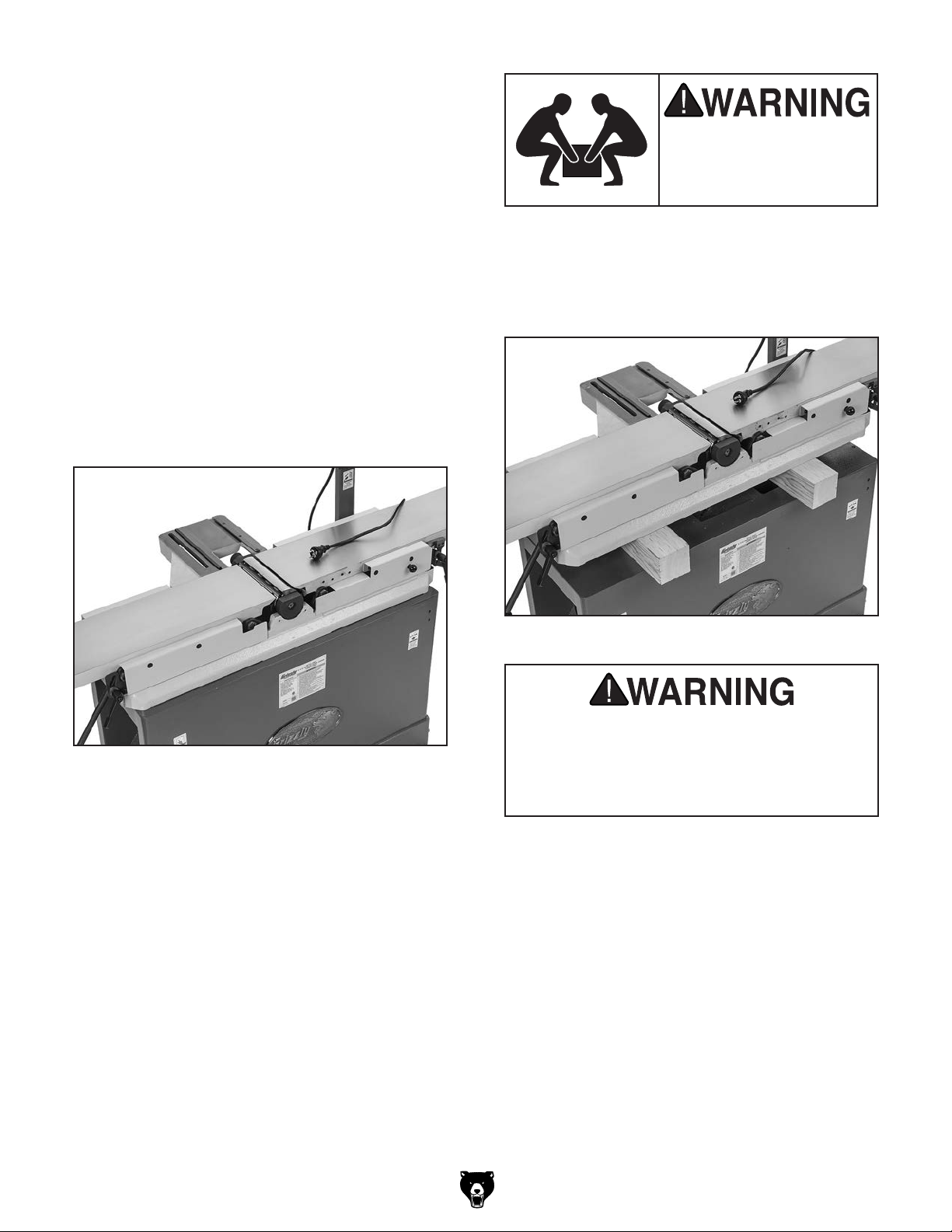
The G0857 and its com-
ponents are very heavy.
Get lifting help to move
heavy items.
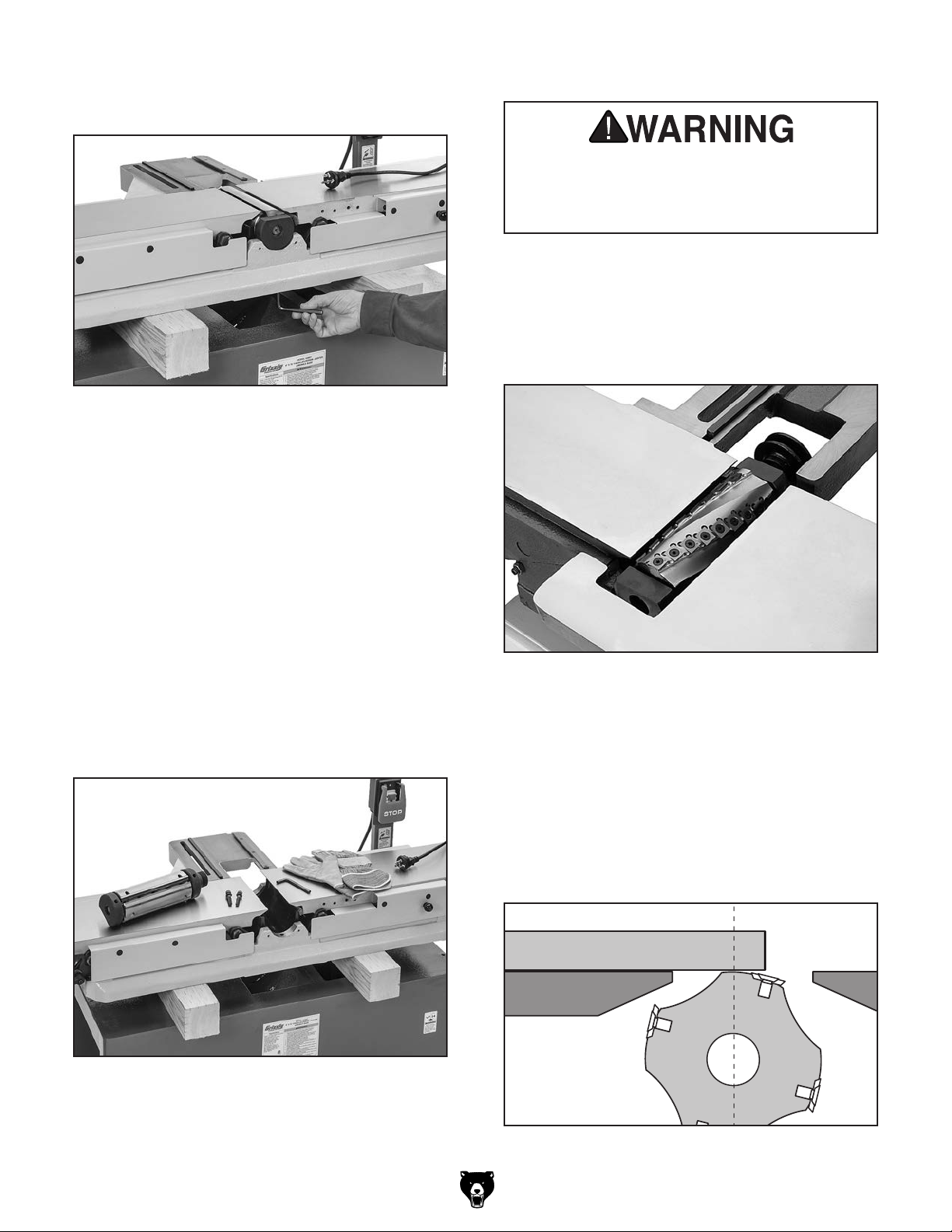
Figure 8. Cutterhead insert at top-dead-center.
Straightedge
Outfeed Infeed
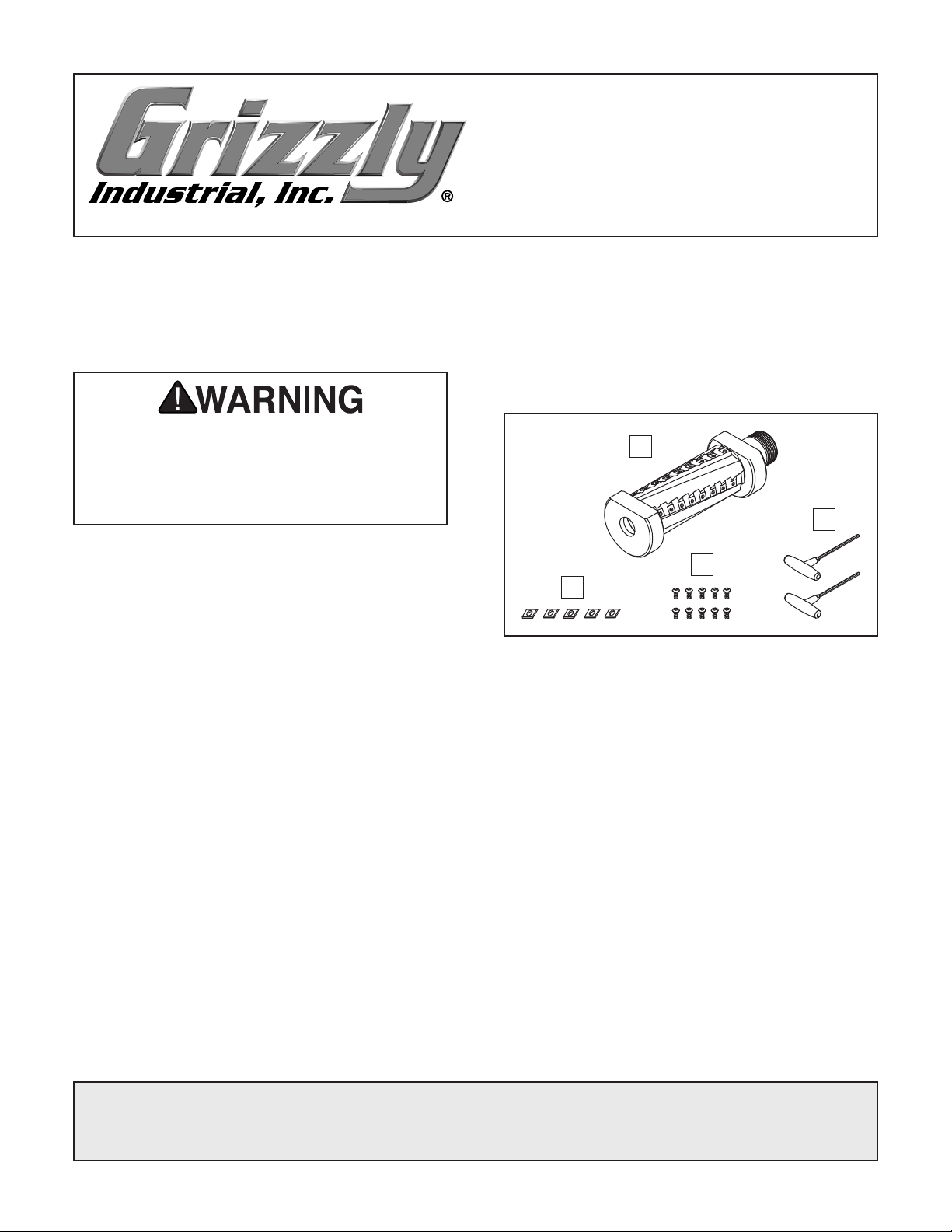
-4- T32058 8" Helical Cutterhead Assembly
When correctly set, carbide insert will just
touch straightedge when insert is at its high-
est point of rotation (see Figure 8).
— If your outfeed table is correctly set, no
adjustments are necessary.
— If insert lifts straightedge off table or if
table is below straightedge, adjust outfeed
table height with outfeed table adjustment
lever until straightedge just touches an
insert at its highest point of rotation.
9. Tighten helical cutterhead in place, and
ensure pulley set screw is tight.
10. With help from an assistant, lift one side of
the table base and carefully remove one
wood block from underneath. Repeat for the
opposite side.
11. Secure jointer table base to cabinet stand
with (3) hex bolts, lock washers, and flat
washers removed earlier.
12. Lock outfeed table, then re-install fence.
13. Re-install V-belt on pulleys. (Refer to instruc-
tions in your G0857 manual for details.)
14. Re-install rabbeting table, cutterhead front
cover, rear access panel, and belt cover.
15. Reset positive stop bolts on infeed and
outfeed tables.
16. Install cutterhead guard back over cutterhead,
making sure that spring tension in guard
is properly set so guard springs back over
cutterhead when it is pulled back and
released.
5. Move straightedge to the other side to deter-
mine if one end of cutterhead body is higher/
lower than the other. (Place feeler gauge
between cutterhead body and straightedge to
determine the height difference.)
— If cutterhead is even or within 0.003" with
outfeed table from one side to other, skip
to Step 8.
— If cutterhead is over 0.003" from one side
to other, go to Step 6.
6. Loosen cap screws securing both bearing
blocks, lift helical cutterhead slightly, then
place a shim beneath bearing block that
needs to be adjusted.
Note: Use shims from your old cutterhead
if available. If not available, newspaper is
approximately 0.003" thick and will work for
shimming (we don't recommend shimming
more than 0.003" on either side, as this may
affect how the bearing block seats in the
casting).
7. Repeat Steps 4–6 and adjust as necessary,
then tighten cap screws on bearing blocks.
8. Place a straightedge on outfeed table
so it extends over cutterhead, and rotate
cutterhead pulley until one of the carbide
inserts is at top-dead-center (TDC), as shown
in Figure 8.