6 OM-EE-20 & 40 (CE) INTERNATIONAL
lever or ring for about 1 second. Repeat
this step, then let the pull ring or valve
lever snap back into the closed position.
WARNING
STAY AWAY FROM THE STEAM THAT IS
BLOWING OUT OF THE SAFETY VALVE.
THE STEAM CAN CAUSE A SEVERE
BURN.
3. Jacket Filling and Water Treatment
The jacket was charged at the factory with
the proper amount of treated water. You
may need to restore this water because it
was lost as steam during venting or by
draining.
a. If you are replacing water lost as steam,
use distilled water. If you are replacing
treated water that ran out of the jacket,
prepare more treated water as directed
in step 4, “Water Treatment Procedure.”
Do not use tap water.
b. Allow the kettle to cool. Remove the
pipe plug from the jacket fill assembly.
c. Open the gate valve and pour in the
distilled or treated water.
d. Hold the safety valve open to allow air
to escape from the jacket while you
pour in the water. Continue to pour until
the water level rises to a point between
the marks on the gauge glass.
e. Close the gate valve and replace the
pipe plug.
f. Any air introduced into the jacket during
filling must be removed to obtain
efficient heating. See “Jacket Vacuum”
above.
4. Water Treatment Procedure
(1) Obtain water treatment compound and a
pH test kit from your Groen distributor.
WARNING
TO AVOID INJURY, READ AND FOLLOW
ALL PRECAUTIONS STATED ON THE
LABEL OF THE WATER TREATMENT
COMPOUND.
(2) Fill a mixing container with the
measured amount of water required.
(See table). Distilled water is
recommended.
Kettle Model Jacket Capacity
EE-20 3¼ Gallons
EE-30 4¼ Gallons
EE-40 5¼ Gallons
EE-60 7¼ Gallons
EE-80 10 Gallons
EE-100 10 Gallons
(3) Hang a strip of pH test paper on the rim
of the container, with about 1 inch of the
strip below the surface of the water.
(4) Measure the water treatment compound
(One way to do this is to add the
compound from a measuring cup.)
(5) Stir the water continuously, while you
slowly add water treatment compound,
until the water reaches a pH between
10.5 and 11.5. Judge the pH by
frequently comparing the test strip color
with the color chart provided in the pH
test kit. If you are color blind have a
person who is not color blind read the
test strip color level.
(6) Record the exact amounts of water and
treatment compound used. These
amounts may be used again, if the
same water sources and compound are
used in the future. However, it is best to
check the pH each time treated water is
prepared.
11
OM-EE
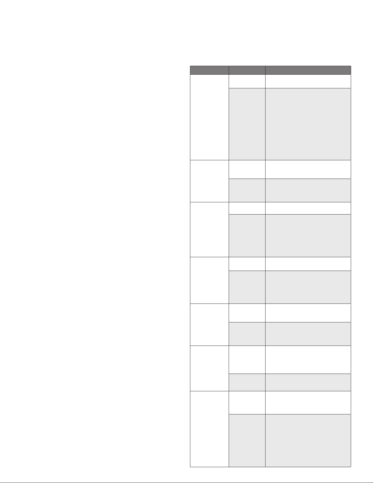
PERIODIC MAINTENANCE
NOTICE: Contact an authorized representative when repairs are required.
A Maintenance & Service Log is provided at the back of this manual. Each time
maintenance is performed on your kettle, enter the date on which the work was
done, what was done, and who did it. Keep this manual on file and available
for operators to use. Periodic inspection will minimize equipment down time and
increase the efficiency of operation. The following points should be checked:
[BY OPERATOR]
1. Check the pressure/vacuum gauge every day. The gauge should show a
vacuum of -20 to -30 inches of mercury (Hg) vacuum or a range of -0.7 to
-1.0 Bar, see “Jacket Vacuum” in this manual.
2. Also check the jacket water level every day. It should be between the marks
on the gauge glass. If the level is low, see “Jacket Filling and Water Treatment”
in this manual.
3. Carefully test the pressure relief valve at least twice each month. With the
kettle operating at 15 psi (105 kPa, 1.1 bar),pull the test lever and let it
snap back to its closed position. If there is little discharge (mostly air), and
the pressure gauge drops back to 0 psi (0 kPa, 0 bar), allow the pressure to
build back to 5 psi (35 kPa, 0.34 bar) and repeat the procedure. (Tip: Using a
screwdriver or other implement to pull the ring will help you avoid contact with
the steam.
[BY SERVICE TECHNICIAN]
4. Electrical wiring should be kept securely connected and in good condition.
5. The inside of the support housing should be kept clean.
6. The gear housing has fittings for lubrication of moving parts. The gears do not
run in oil, so periodic lubrication with grease is necessary.
7. Frequency of lubrication depends on operating conditions, but it should be
done at least once every six months.
8. Use a #2 grade LGI lithium grease to add grease through Zerk fittings on gear
housing until it flows out of the bearings around the trunnion shaft.
9. Place liberal amounts of grease on the gear to cover the arc that is in contact
with the worm gear.
10. Keep electrical wiring and connections in good condition.
11. Keep the inside of the control console clean and dry.
JACKET VACUUM/REMOVING AIR FROM JACKET
When the kettle is cold, a positive pressure reading on the pressure/vacuum gauge
or a reading near 0 psi (0 kPa, 0 bar) indicates that there is air in the jacket. Air in
the jacket acts as an insulator, and slows kettle heating.
To remove air:
1. Start the unit. (Be sure there is water or product in the kettle when heating).
2. When the pressure/vacuum gauge reaches a positive pressure reading of 5 psi
(35 kPa, 0.34 bar), release the trapped air and steam by pulling up the safety
valve ring for about five seconds. Repeat this step three or four times. Then let
the pull ring snap back into the closed position.
3. If there is little discharge (mostly air), and the pressure gauge drops back to 0
psi (0 kPa, 0 bar), allow the pressure to build back to 5 psi (35 kPa, 0.34 bar)
and repeat the procedure.
4. Once steam has been vented from the jacket as described in b, above, remove
the hot water from the kettle and replace it with cold. This will condense steam
in the kettle jacket, and the pressure gauge should show -20 to -30 inches
of mercury (Hg) vacuum or a range of -0.7 to -1.0 Bar. If it does not, or if the
vacuum is leaking down, contact an authorized service agency to correct the
problem.
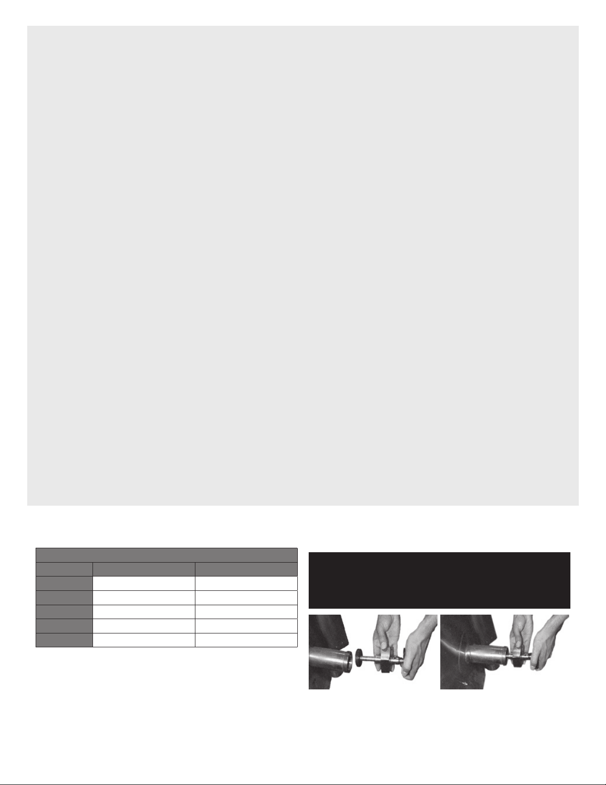
PRESSURE RELIEF VALVE
At least twice a month, test the pressure relief valve. Test the valve with the kettle
operating at 15 PSI (105 kPa, 1.1 bar), by holding the test ring for at least five
seconds. Then release the ring and permit the valve to snap shut. If the ring does
not activate, if there is no discharge, or if the valve leaks, stop using the kettle
immediately and contact a authorized service representative.
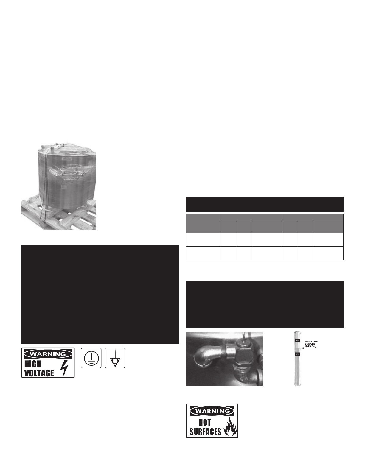
JACKET FILLING
The jacket was charged at the factory with the proper amount of treated water.
You may need to restore this water, either because it was lost as venting steam or
by draining. If you are replacing water lost as steam, use distilled water. If you are
replacing treated water that ran out of the jacket, prepare more treated water as
directed in “Water Treatment Procedure,” below.
1. Allow the kettle to cool completely. The procedure will be easier with the kettle
under vacuum (pressure gauge reading below zero).
2. Allow the kettle to cool completely. Remove the pipe plug from the jacket fill
assembly. Pour in the distilled or treated water. Using a funnel will help you
in this process. Hold the pressure relief valve open while you pour, to let air
escape from the jacket. Continue adding water until the water level rises to the
center of the round sight glass.
3. Position a funnel in the opening and fill it with properly treated water.
4. Air that gets into the jacket during the filling operation must be removed,
because it will make heating less efficient. Follow the procedure in Jacket
Vacuum/Removing Air From Jacket above, to restore a negative pressure
reading.
WATER TREATMENT
1. Obtain water treatment compound and a pH test kit from your authorized parts
distributor.
2. Fill a mixing container with the measured amount of water required. (See
table). Distilled water is recommended.
Kettle Model Jacket Capacity
EE-20 3-1/4 Gallons (12.3 liters)
EE-40 4-1/2 Gallons (17.0 liters)
3. Hang a strip of pH test paper on the rim of the container, with about 1” (2.54
cm) of the strip below the surface of the water.
4. Measure the water treatment compound (ones way to do this is to add the
compound from a measuring cup).
5. Stir the water continuously, while you slowly add water treatment compound,
until the water reaches a pH between 10.5 and 11.5. Judge the pH by
frequently comparing the test strip color with the color chart provided in the pH
test kit. If you are color blind use an electroanalytical instrument to measure
the pH level or have a person who is not color blind read the test strip color
level.
6. Record the exact amounts of water and treatment compound used. These
amounts may be used again, if the same water sources and compound are
used in the future. However, it is best to check the pH each time treated water
is prepared.