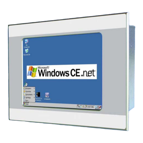
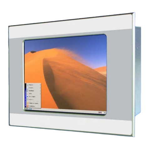
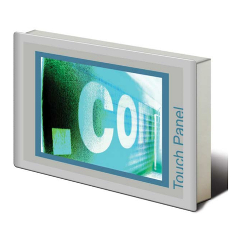
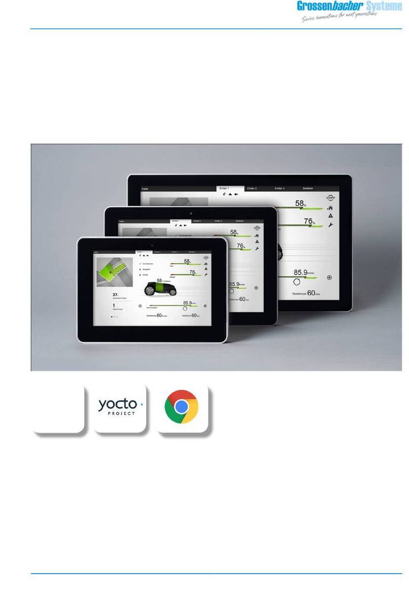
Grossenbacher Systeme EthernetPanel EP-370 Series Operating and installation instructions

DEVICE DESCRIPTION
EthernetPanel
Hardware EthernetPanel
Grossenbacher Systeme AG
Spinnereistrasse 10, CH-9008 St. Gallen
Phone +41 (0)71 243 29 29 / Fax +41 (0)71 243 29 28
info@gesys.ch / www.gesys.ch
Grossenbacher Systeme GmbH
Ruhrstrasse 15, DE-63452 Hanau
Phone +49 (0)6181 6751 999/ Fax +49 (0)6181 6751 998
EP-370
DVS 60646-V1.0

EthernetPanel
Hardware EthernetPanel
DVS 60646 V1.0 © 2010 by Grossenbacher Systeme AG
Copyright
Keep documentation for future use!
This documentation is the intellectual property of Grossenbacher Systeme AG, which also has
the exclusive copyright. Any modification of the content, duplication or reprinting of this
documentation, as well as any distribution to third parties can only be made with the express
permission of Grossenbacher Systeme AG.
Grossenbacher Systeme AG does not accept any liability for damages arising from the use of
any incorrect or incomplete information contained in this documentation or any information missing
therefrom.
Grossenbacher Systeme AG reserves the right to make complete or partial modifications to this
document.
All brand and product names are trademarks or registered trademarks of the owner concerned
DVS 60646-V1.0

EthernetPanel
Hardware EthernetPanel
© 2010 by Grossenbacher Systeme AG DVS 60646 V1.0 3
Proper use
The device must only be used for the applications specified in the
device description and only in conjunction with the components
recommended by Moeller GmbH.
Warning
Trouble-free and safe operation of the product can only be ensured if
the measures relating to proper transport, storage, assembly,
installation and careful operation are strictly observed.
The device must not be switched on when it is covered with
condensation. When changing its location from cold to warm allow the
device to acclimatize to the new conditions before commissioning.
No warranty claims will be recognized for faults arising from the
improper handling of the device.
The device should not be used for the implementation of any safety
functions relating to the protection of personnel and machinery.
No liability is accepted for claims for damages arising from a failure or
functional defect in the device.
All data specified in this document does not represent guaranteed
specifications in the legal sense.
DVS 60646-V1.0

EthernetPanel
Hardware EthernetPanel
4 DVS 60646 V1.0 © 2010 by Grossenbacher Systeme AG
Safety instructions for the user
This device description contains the information required for the
proper use of the products described therein. Sections 1 to 10 address
technically qualified personnel and Section onwards addresses
personnel not requiring any technical knowledge.
Qualified personnel in the sense of the safety instructions given in this
device description or on the product itself are persons who:
as engineering personnel are either familiar with the safety concepts of
automation,
or as operating personnel, are instructed in the use of automation
components and are familiar with the contents of this device
description relating to the operation of the device,
or as commissioning or service personnel are suitably trained for the
repair of automation devices and are authorized to commission circuits
and devices/systems in accordance with standard safety engineering
principles.
DVS 60646-V1.0

EthernetPanel
Hardware EthernetPanel
© 2010 by Grossenbacher Systeme AG DVS 60646 V1.0 5
Contents
1
Explanation of symbols................................................. 7
2
Introduction.................................................................... 9
3
Device Versions ........................................................... 11
3.1 Specification ......................................................................... 11
3.2 Accessories ..........................................................................12
4
Features........................................................................ 13
5
Commissioning............................................................ 15
5.1 Overview of connections ......................................................15
5.2 Connecting the power supply ...............................................15
5.3 Power Fail and UPS .............................................................16
5.4 Fuse .....................................................................................16
5.5 Battery ..................................................................................16
5.6 Preparing the shield connections .........................................17
5.7 Connecting the Ethernet.......................................................18
5.8 Connecting the USB-Interface..............................................18
5.9 Connection for COM1 serial interface (RS232)....................19
5.10 CAN interface...................................................................19
5.11 Inserting / Removing the CompactFlash™.......................22
5.12 Inserting / Removing the SDCARD™ ..............................22
5.13 Expansion PC/104-Slot....................................................22
5.14 Expansion PC/104-Slot....................................................22
6
Operation...................................................................... 23
6.1 Startup / Shutdown behaviour ..............................................23
6.2 System-Settings ...................................................................23
7
Mounting instructions ................................................. 25
7.1 General mounting instructions..............................................25
7.2 Mounting in the front panel - General...................................25
7.3 Front panel cutout 5,7“ to 15“ ..............................................26
7.4 Mechanical dimensions - Frontside 5,7“ to 15“....................29
7.5 Mechanical dimensions - Rear side 5,7“ to 15 .....................32
8
Notes on the touch-screen.......................................... 39
8.1 Basic touch-screen function .................................................39
9
Backlight, contrast....................................................... 41
9.1 Contrast................................................................................41
9.2 Backlight...............................................................................41
9.3 Diagnostics...........................................................................41
10
Maintenance and repair............................................... 43
11
Technical data.............................................................. 45
12
Disposal........................................................................ 47
13
EU Conformity and Standards.................................... 49
14
Revision history........................................................... 51
15
Alphabetical index ....................................................... 53
DVS 60646-V1.0

EthernetPanel
Hardware EthernetPanel
6 DVS 60646 V1.0 © 2010 by Grossenbacher Systeme AG
DVS 60646-V1.0

EthernetPanel
Hardware EthernetPanel
© 2010 by Grossenbacher Systeme AG DVS 60646 V1.0 7
1 Explanation of symbols
Danger warnings
The following information is for your personal safety and the prevention of
damage to the device described or connected devices.
Safety instructions and warnings for the prevention of danger to the life and
health of users or service personnel, and for the prevention of damage are
highlighted in this document by the following pictograms. “Warning” and
“Information” pictograms are shown in this document.
Warnings indicate the following:
Death, serious injury or substantial material damage may occur if the related
safety measures are not implemented.
The individual “Warning” pictograms have the following meaning:
Caution! General!
An instruction to be observed in order to ensure protection
against hazards and the safe operation of the device. The
specified procedure should be observed.
Caution! Electric shock!
Persons may be exposed to dangerous voltages that occur
in electrical systems. There is a danger of electric shock if a
live part is touched.
Caution! Observe ESD measures!
Electrostatic discharge may destroy electronic components.
Information pictograms indicate the following:
Important information about the product or the relevant section of the
document, requiring the particular attention of the reader.
The “Information” pictogram has the following meaning:
Indicates important and instructional information.
DVS 60646-V1.0

EthernetPanel
Hardware EthernetPanel
8 DVS 60646 V1.0 © 2010 by Grossenbacher Systeme AG
DVS 60646-V1.0

EthernetPanel
Hardware EthernetPanel
© 2010 by Grossenbacher Systeme AG DVS 60646 V1.0 9
2 Introduction
The new generation of EthernetPanel EP-370 devices features the 1GHz
class continously from 5,7” up to 15” within the openAutomation concept of
Grossenbacher Systeme AG. They are based on the Intel Atom 1,1GHz-
x86-CPU with WindowsCE/XP/XPe and Ethernet on-board.
In the basic configuration the device can be used as „HMI“ or as a user
programmable „HMI-Open“ with 2xEthernet and USB onboard. The
fieldbus interfaces EtherCAT, CANopen, ProfibusDP-Master/Slave or MPI
are available optionally.
With CoDeSys V3 IEC-61131 Soft-PLC the device can be used as "HMI-
Control" with EtherCAT-Master, Codesys TargetVisu, WebVisu, integrated
Soft-PLC and with CoDeSys Soft-Motion. Alternatively the STEP7®
compatible Soft-PLC AT-S7 is available, which can be programmed with
standard SIMATIC Manager via Ethernet.
An exchangeable Compact-Flash™ is used as mass storage device.
Without moving parts the devices are “at home” in rugged environment!
For fast, intuitive and fatigue free operation two approved touch-screen
technologies are available: the service free infrared touch-screen with
scratch resistant safety glass or the seamless resistive touch-screen.
Features:
• WindowsCE
• Touchscreen
• Intel Atom CPU 1,1 or 1,6GHz
• 2xEthernet onboard
• Exchangeable CompactFlash™ and SDCARD
• EtherCAT, Profibus, MPI, CANopen (Option)
• Soft-Motion (Option)
The devices can be installed in control panels or control desks without any
problem. The devices are not designed for mobile use.
This device description is a reference for the technical data, installation,
terminals, commissioning, operation, and maintenance of all EthernetPanel
versions.
Additional documentation:
System description WindowsCE DVS 49631
System description Windows XP DVS 52696
System description CoDeSys V3 Soft-PLC DVS 60742
DVS 60646-V1.0

EthernetPanel
Hardware EthernetPanel
10 DVS 60646 V1.0 © 2010 by Grossenbacher Systeme AG
DVS 60646-V1.0

EthernetPanel
Hardware EthernetPanel
© 2010 by Grossenbacher Systeme AG DVS 60646 V1.0 11
3 Device Versions
In this chapter all device versions of the EthernetPanels and available
accessories are specified.
3.1 S
PECIFICATION
General features of all device versions:
Processor:
1.1GHz / 1.6GHz Intel ATOM x86 CPU
Memory:
512MB /1GB
Mass storage: CompactFlash-Slot, SDCARD-Slot
Interfaces: 2 x Ethernet GBit
4 x USB Master
1 x RS232
1 x CAN
Power supply: 24VDC
EP-370-BOX-000
Ord.No : 50 81 389
EthernetPanel BOX for DIN rail mounting
EP-370-05I-000
Ord.No : 50 81 383
EthernetPanel 5,7” TFT 640x480 256k colours
Infrared touch-screen
EP-370-07I-000
Ord.No : 50 81 382
EthernetPanel 7,5” TFT 640x480 256k colours
Infrared touch-screen
EP-370-10I-000
Ord.No : 50 81 381
EthernetPanel 10,4” TFT 640x480 256k colours
Infrared touch-screen
EP-370-10R-000
Ord.No : 50 81 387
EthernetPanel 10,4” TFT 640x480 256k colours
Resistive touch-screen
EP-370-12I-000
Ord.No : 50 81 380
EthernetPanel 12” TFT 800x600 256k colours
Infrared touch-screen
EP-370-12R-000
Ord.No : 50 81 388
EthernetPanel 12” TFT 800x600 256k colours
Resistive touch-screen
EP-370-15I-000
Ord.No : 50 81 379
EthernetPanel 12” TFT 1024x786 256k colours
Infrared touch-screen
EP-370-15R-000
Ord.No : 50 81 386
EthernetPanel 12” TFT 1024x768 256k colours
Resistive touch-screen
DVS 60646-V1.0

EthernetPanel
Hardware EthernetPanel
12 DVS 60646 V1.0 © 2010 by Grossenbacher Systeme AG
3.2 A
CCESSORIES
Runtime-System
Ord.No: 50 56 993
RTS HMI CEx86 QAZ510P
WindowsCE6 Professional and EPAM-RTS
preinstalled on CompactFlash
Ord.No: 50 56 994
RTS HMI CEx86 QAZ510P 3S V3
WindowsCE6 Professional, EPAM-RTS and
Codesys-RTS V3 preinstalled on CompactFlash
Ord.No: 50 56 995
RTS HMI CEx86 QAZ510P AT-S7
WindowsCE6 Professional, EPAM-RTS and AT-S7-
RTS preinstalled on CompactFlash
Ord.No: 50 56 996
RTS HMI WindowsXP POSReady QAZ510P HD
WindowsXP embedded preinstalled on Harddisk
Ord.No: 50 56 997
RTS HMI WindowsXP POSReady QAZ510P CF
WindowsXP embedded preinstalled on
CompactFlash
CompactFlash™
Ord.No : 50 56 825
CompactFlash™ 256MB with WindowsCE Bootloader
Ord.No : 50 56 827
CompactFlash™ 1GB with WindowsCE Bootloader
SDCARD
Ord.No: 32 01 352
SDCARD 512MB, INDUSTRIAL
Ord.No: 32 01 353
SDCARD 1GB, INDUSTRIAL
Connector for power
supply
Ord.No : 12 17 017
3pol Phoenix Contact, MSTB2.5/3-ST-5.08
Profibus-DPM
(PC104)
Ord.No : 32 12 860
Profibus DP-Master; configurable Master/Slave/MPI
Profibus-DPS/MPI
(PC104)
Ord.No : 32 12 859
Profibus DP-Slave/MPI
2.CAN (PC104)
Ord.No : 32 12 890
2.CAN
DVS 60646-V1.0

EthernetPanel
Hardware EthernetPanel
© 2010 by Grossenbacher Systeme AG DVS 60646 V1.0 13
4 Features
Feature Comment
Display
Display Size 5,7“ / 7,5“ / 10,4“ / 12.1“ / 15”
Type TFT 256k Colours
Touch-screen Infrared touch-screen Resolution 5,7“: 45 x 33 / 7,5“: 57 x 43
10,4“: 81 x 61 …/… 12“: 93 x 71
15“: 115 x 87
Resistive touch-
screen
Resolution 12 Bit (0-4096)
Realtime clock Yes Battery-backed
Processor Type Intel ATOM
Clock 1.1GHz/1.6GHz
Mass storage CompactFlash™ Type I and II (Microdrives™ supported)
Memory SDRAM MB 512MB / 1GB
Retain memory kB 256kB1
Exchangeable
memory
SDCARD
Memorystick
Type SD-Card-Slot or Memorystick (optional via USB)
Interfaces COM1 Type RS232, max. 115 kBit/s
COM2 Type RS232 internally for touch-screen
Ethernet 1-2 Type 10 / 100 / 1000 MBit/s
USB 1-4 (2.0) Type 1.5 / 12 / 480 MBit/s
Keyboard Type Optional via USB
Mouse Type Optional via USB
PC/104 Type 8bit PC/104 Slot
(installation of modules only factory made)2
Expansion-
Slot
Count 1 Slot
Power supply Type 24VDC, NOT isolated
Device cooling Type passive (fanless)
CompactFlash™ memory media are NOT suitable for
cyclical data logging due to the limited number of write
cycles (normally 1,000,000).
1Retain data will be saved on power fail to CompactFlash
2Only a subset of PC-104
DVS 60646-V1.0

EthernetPanel
Hardware EthernetPanel
14 DVS 60646 V1.0 © 2010 by Grossenbacher Systeme AG
DVS 60646-V1.0

EthernetPanel
Hardware EthernetPanel
© 2010 by Grossenbacher Systeme AG DVS 60646 V1.0 15
5 Commissioning
5.1 O
VERVIEW OF CONNECTIONS
No. Element Description
1 Function earth
2 24VDC power supply ÎChap. 5.2
3 COM1 ÎChap. 5.9
4 CAN ÎChap. 5.10
5 4xUSB ÎChap. 5.8
6 2xEthernet ÎChap. 5.7
7 SDCARD-Slot ÎChap. 5.12
8 Battery ÎChap.5.5
9 CompactFlash™ ÎChap. 5.11
10 PC/104 Steckplatz ÎChap. 5.13
5.2 C
ONNECTING THE POWER SUPPLY
The EthernetPanel devices belongs to protection class 3. The system power
supply must be provided with a 24VDC SELV voltage (ÎSection 11). The
power supply is NOT isolated. The GND connection is directly connected to
the housing potential. The device is protected with a fuse (note
disconnection capacity ÎSection 11). A reverse polarity protective device is
used to protect the device in the event of reversed poles. Operation,
however, is only possible if the connection was made correctly.
Connections for the EthernetPanel must comply with specific, local
regulations.
1
234 5 6
87
10
9
DVS 60646-V1.0

EthernetPanel
Hardware EthernetPanel
16 DVS 60646 V1.0 © 2010 by Grossenbacher Systeme AG
The connection must be made as follows:
1.
The cross-section of the power supply cable must be at least 0.75 mm²
and a maximum of 2.5 mm².
2. A flexible lead or wire can be used for the connection.
3. The current consumption (ÎSection 11) must be taken into account
when implementing the power supply.
4. The functional earth is not compulsory for operation. But it can help to
avoid disturbance caused by potential differences.
5. The GND connection is directly connected to the housing potential
6. For safety reasons the wires should be fixed together near by the
connector
The plug connector (socket connector with screw terminals) is supplied with
the device for connection.
Connector assignment
In the event of reverse connection and simultaneous
connection of a further 0V connection, e.g. GND
connection of the COM1 interface, the fault current flows
via this OV connection. If the housing is not lying well set
on the OV potential, the result can be destruction of the
device or of the external components!
For safety reasons the wires should be fixed together
near by the connector.
5.3
P
OWER
F
AIL AND
UPS
The device includes a power fail functionality. The power fail mechanism
prevents the loss of retain data if a Soft-PLC (Codesys or AT-S7) is used.
The retain data are stored on CompactFlash when the PLC is shutting down
and are read out again when the PLC starts up. (for details s.a. System
description Codesys Soft-PLC or AT-S7)
The standard integrated UPS-solution can bridge brownouts up to about 5s.
5.4 F
USE
The device is protected with a fuse internally. The fuse can not be changed
by the user.
5.5 B
ATTERY
The internal battery is used for backing up the real-time clock and has a
lifetime of at least 5 years. The battery can be replaced by the user. (Type:
CR2032).
(plug connector: 3pol Phoenix MSTB2.5/3-ST-
5.08, RM 5.08mm, Phönix Ord.Nr 1757022)
Designation Function
+24 VDC +24VDC power supply
reserved
0 V 0V power supply
24VDC 0VDC
reserved !
DVS 60646-V1.0

EthernetPanel
Hardware EthernetPanel
© 2010 by Grossenbacher Systeme AG DVS 60646 V1.0 17
5.6 P
REPARING THE SHIELD CONNECTIONS
The preparation of the data and signal cables is an important factor for the
electromagnetic compatibility (EMC) of the EthernetPanel, both in terms of
interference immunity and emission.
The RS232 and CAN interface are connected via D-Subminiature plug
connectors in accordance with DIN 41652. Only use metal or metallised
connector casings with a cable clamp for strain relief fastened or clamped
on the connector. The clamping of the cable shield ensures an optimum
contact area and a low impedance connection with the connector casing of
the EthernetPanel.
The following procedure is recommended for making the low-impedance
connection for the cable shield:
1. Strip the cable.
2. Shorten the exposed shield braid by approx. 3 cm.
3. Turn back the braid over the cable sheath.
4. Use a heat shrinkable tubing or rubber grommet to cover the exposed
cable sheath with the folded back shield braid so that 5 to 8 mm of
exposed cable shield is left at the sheath end and is cleanly covered at
the back.
5. Fit the connector
6. The cable is then fastened at the exposed shield braid and the cable
sheath below it directly underneath the cable clamp strap of the
connector casing.
Connection work should be carried out with special care
in order to ensure trouble-free operation.
The EMC values stated in the technical data can only be
guaranteed if the cables are prepared according to the
following specifications.
Metal or metallised
D-subminiature connector
Metallic
connector shroud
Fastening
screws
connector casing
Heat shrinkable
tubing for covering
the shield braid
Shield braid pulled
back over the
cable sheath
Strap for cable clamp
and contacting of the
cable shield with the
connector casing
DVS 60646-V1.0

EthernetPanel
Hardware EthernetPanel
18 DVS 60646 V1.0 © 2010 by Grossenbacher Systeme AG
5.7 C
ONNECTING THE
E
THERNET
The Ethernet-Interface is compatible with standard IEEE 802.3
(10/100/1000BASE-T).
The network connection is implemented via a Cat 5e cable with shield and
RJ45 connectors. The maximum cable length and transfer speed is limited
by the cable quality in EIA/TIA 568 TSB-36. Cable lengths up to 100m are
possible.
Two diagnosis LEDs are available:
Orange: LINK (connection to HUB or to another device)
Green: ACT (sending or receiving)
Cables connected to the Ethernet must be laid separately from the low-
voltage cables.
To ensure disturbance-free operation, it is strongly
recommended to use network cables with shield.
Connector assignment
RJ45
connector
Pin No. Signal Description
1 TXD+
2 TXD-
3 RXD+
4 -
5 -
6 RXD-
Socket, 8pole
7 -
RJ45
8 -
5.8 C
ONNECTING THE
USB-I
NTERFACE
The USB Interface is compatible to USB-standard Version 2.0
The use of the USB-Interface requires support by the operating system.
Cables connected to the USB must be laid separately from the low-voltage
cables.
A
CT LINK
3
1
2
3
4
5
6
7
8
DVS 60646-V1.0

EthernetPanel
Hardware EthernetPanel
© 2010 by Grossenbacher Systeme AG DVS 60646 V1.0 19
5.9 C
ONNECTION FOR
COM1
SERIAL INTERFACE
(RS232)
The serial Interface COM1 is PC-compatible. This interface is not isolated.
The GND connection is implemented directly on the housing potential (Î
Section 11).
Connector Pin No. Signal Description
1 DCD
2 RXD
3 TXD
4 DTR
5 GND
6 DSR
7 RTS
Connector
9pole
8 CTS
SubD
9 RI
Cables connected to the programming interface (Ethernet or serial) must be
laid separately from the low-voltage cables.
To ensure disturbance-free operation, it is strongly
recommended to use cables with shield.
5.10 CAN
INTERFACE
The communication interface is defined in accordance with the CiA CAN
Specification V2.0 part B. The fully-integrated CAN unit supports the sending
and receiving of frames with an 11-bit identifier. The type of configuration
selected depends on the software protocol. The baud rate can be selected in
a wide range, and only the standard CiA baud rates are implemented.
CAN connector
Sub-D 9 Pole male
Connect
or
Pin No. Assignme
nt
Function
1 -
2 CAN
LOW
Negative data signal
3 GND Signal Ground (ground potential)
4 -
5 -
6 GND Signal Ground (ground potential)
7 CAN
HIGH
Positive data signal
8 -
9 -
Case Case Cable shield
The CAN interface is NOT isolated.
The max. baud rate is 1MBit/s.
1 2 3 4 5
6 7 8 9
5
5
94
83
72
61
5
94
83
72
61
1 2 3 4 5
6 7 8 9
6
DVS 60646-V1.0

EthernetPanel
Hardware EthernetPanel
20 DVS 60646 V1.0 © 2010 by Grossenbacher Systeme AG
The terminating resistor must be implemented externally,
e.g. in the connector, and is not part of the device.
The CAN connector is not provided with a supply for
third-party devices.
A detailed description of the wiring is provided in the
“Codesys Soft-PLC” system description
Wiring instructions
The stations on the bus system are connected via fieldbus lines complying
with ISO 11898. The cables must accordingly have the following electrical
characteristics:
Parameter Abbreviation Unit Value Value Value Note
min. nom. max.
Impedance Z Ω108 120 132 Measured between two
signal lines
Specific
resistance
mΩ/m 70 For the receiver
module, the differential
voltage on the bus
cable depends on cable
resistance between it
and the sender
Cable delay ns/m 5 The mininum delay
between to points on
the bus is 0. The
maximum delay is
determined by the bit
timing and the delays of
the sender and receiver
circuits
The figure shows the minimum wiring with shielding between two bus
stations with the Sub-D connector as an example. A bus terminating resistor
(120 Ohm between Pin 2 and Pin 7 of the Sub-D connector) must be
connected at the beginning and the end of each CAN bus. Do not swap
around the two signal wires!
Protective ground
Shield
Interface 1
Protective ground
DVS 60646-V1.0
This manual suits for next models
18
Table of contents
Other Grossenbacher Systeme Touch Panel manuals

Grossenbacher Systeme
Grossenbacher Systeme EP-300 User manual

Grossenbacher Systeme
Grossenbacher Systeme Combi-Line Operating and installation instructions

Grossenbacher Systeme
Grossenbacher Systeme SmartPanel SP-284-10P-R00 User manual

Grossenbacher Systeme
Grossenbacher Systeme WebPanel WP-284 Series User manual

Grossenbacher Systeme
Grossenbacher Systeme WebPanel WP-284-10P-000 User manual

Grossenbacher Systeme
Grossenbacher Systeme WebPanel WP-284-10P-000 User manual