manuals.online logo
Brands
  1. Home
  2. •
  3. Brands
  4. •
  5. Grossenbacher Systeme
  6. •
  7. Touch Panel
  8. •
  9. Grossenbacher Systeme SmartPanel SP-284-10P-R00 User manual

Grossenbacher Systeme SmartPanel SP-284-10P-R00 User manual

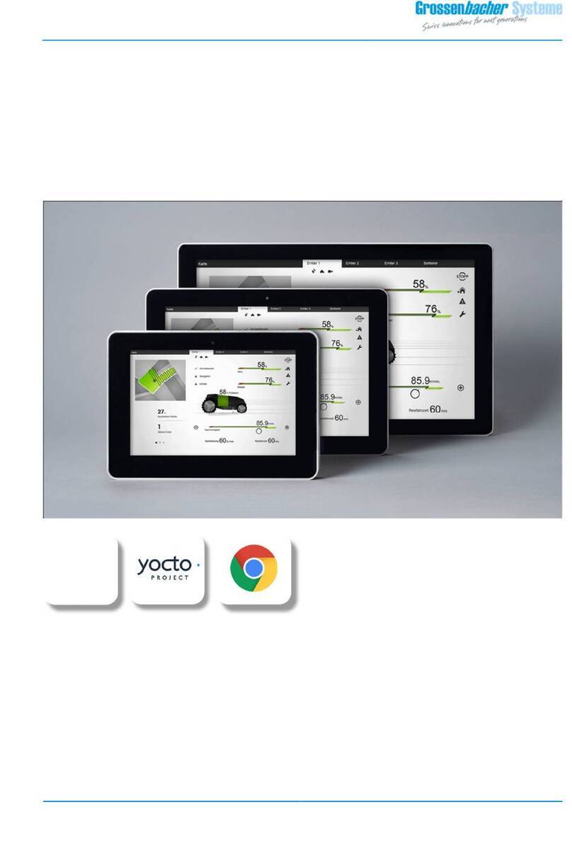
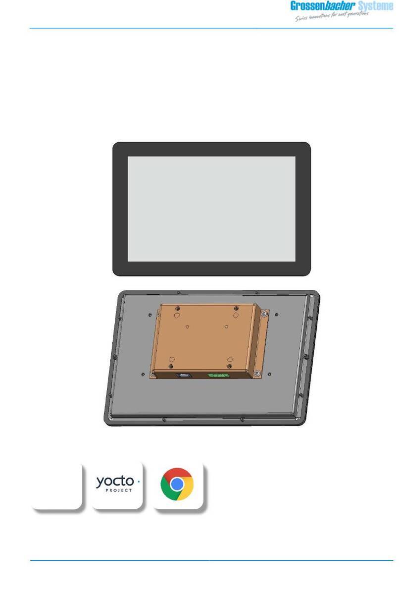
SmartPanel
SP-284-10P-R00
Grossenbacher Systems AG
Spinnereistrasse 10, CH-9008 St. Gallen
T +41 71 243 29 29 / F +41 71 243 29 28
info gesys.ch / www.gesys.ch
Grossenbacher Systems GmbH
Feldwiesenstrasse 8, DE-79807 Lottstetten
T +49 7745 928 69 71 / F +49 7745 928 95 59
sales.de gesys.ch
OPERATING INSTR CTIONS
i.MX 8
Quad
SmartPanel
SP-284-10P-R00
Grossenbacher Systems AG
Spinnereistrasse 10, CH-9008 St. Gallen
T +41 71 243 29 29 / F +41 71 243 29 28
info gesys.ch / www.gesys.ch
Grossenbacher Systems GmbH
Feldwiesenstrasse 8, DE-79807 Lottstetten
T +49 7745 928 69 71 / F +49 7745 928 95 59
sales.de gesys.ch
Copyright notice
These operating instructions and all illustrations contained therein are protected by copy-
right. Any use outside the limits of copyright law is prohibited without the prior written
consent of Grossenbacher Systeme AG and is punishable by law. This applies to
reproductions, translations, microfilming, storage, and processing in electronic systems.
The Grossenbacher Systeme AG accepts no liability for damage, caused by the use of
incorrect or inadequate information or due to missing information in these documents.
The Grossenbacher Systeme AG reserves the right to change this document in part or in
full.
All brand and product names are trademarks or registered trademarks of their respective
titleholders/owners.
Overview of changes
Version Date of issue Amendment
01 14.12.2023 First release in English.
Bases on German version with Doc-ID 122587-01.
Contents
SP
-
284
-
10P
-
R00
Doc
-
ID: 122611
-
01
-
I
-
Contents
1 Introduction ........................................................................................................................... 3
1.1 Means of presentation ............................................................................................................... 3
1.1.1 Section-related warnings ................................................................................................ 3
1.1.2 Embedded warnings ....................................................................................................... 4
1.1.3 Other means of presentation ......................................................................................... 4
1.2 Symbols used in the instructions ............................................................................................... 5
1.3 Warranty and liability ................................................................................................................. 5
1.4 Applicable documents ............................................................................................................... 5
1.5 Order number ............................................................................................................................ 6
1.6 Service / Product support .......................................................................................................... 6
2 Security .................................................................................................................................. 7
2.1 Intended use .............................................................................................................................. 7
2.1.1 Structural changes to the device .................................................................................... 7
2.1.2 Foreseeable misuse ........................................................................................................ 7
2.2 Requirements for personnel ...................................................................................................... 8
3 Description ............................................................................................................................. 9
3.1 Device overview ....................................................................................................................... 10
3.2 Connections / Interfaces .......................................................................................................... 11
3.3 LED display for board controller and backup status ................................................................ 12
3.4 Freely configurable LED display ............................................................................................... 13
3.5 Technical data .......................................................................................................................... 14
3.5.1 Dimensions ................................................................................................................... 14
3.5.2 Power supply / Power consumption ............................................................................ 14
3.5.3 Electromagnetic compatibility / protection class ......................................................... 15
3.5.4 Specifications ................................................................................................................ 16
3.5.5 Ambient conditions ...................................................................................................... 18
3.5.6 Certifications ................................................................................................................. 18
4 Transportation / Storage / Scope of delivery ......................................................................... 19
4.1 Transportation .......................................................................................................................... 19
4.2 Storage ..................................................................................................................................... 19
4.3 Scope of delivery ...................................................................................................................... 19
5 Assembly .............................................................................................................................. 21
5.1 Preparatory measures .............................................................................................................. 21
5.2 Dimensions / Installation cut-out............................................................................................. 22
5.3 Device installation .................................................................................................................... 24
6 Connection ........................................................................................................................... 25
6.1 Power supply ............................................................................................................................ 25
6.2 Data connections ..................................................................................................................... 28
6.2.1 Ethernet interfaces ETH1/ETH2 (Ethernet/EtherCAT) .................................................. 28
Contents
-
II
-
Doc
-
ID: 122611
-
01
SP
-
284
-
10P
-
R00
6.2.2 USB interface n (USB1/USB2) ....................................................................................... 30
6.2.3 COM interface (RS485) ................................................................................................. 31
6.2.4 CAN interface ................................................................................................................ 33
6.3 Memory card / Removable disk (microSD card)...................................................................... 36
7 Switch-on and switch-off behavior / Backup handling ............................................................ 37
8 Cleaning / Repairs ................................................................................................................. 39
8.1 Cleaning ................................................................................................................................... 39
8.2 Repairs ..................................................................................................................................... 39
9 Disposal ................................................................................................................................ 41
1 Introduction
SP
-
284
-
10P
-
R00
Doc
-
ID: 122611
-
01
-
3
-
1Introduction
These operating instructions are an integral part of the SmartPanel SP-284-10P-R00
(hereinafter referred to as device or SmartPanel).
The operating instructions must be read, understood, and applied by all persons responsible
for installing the device.
In addition to the operating instructions, generally applicable, statutory, and other binding
regulations on accident prevention and environmental protection in the country of use
must be observed.
1.1 Means of presentation
As a note and as a direct warning of dangers, text passages in these operating instructions
that require special attention are marked as follows:
1.1.1 Section-related warnings
Section-related warnings apply not only to a specific action, but to all actions within a
section.
Structure
SIGNAL WORD
Symbol to
explain the
danger
Nature and source of the danger
Possible consequences of non-compliance
►Measures to avoid the danger
Hazard levels
DANGER
Danger with a high degree of risk
If the danger is not avoided, this will result in death or serious injury.
WARNING
Danger with medium degree of risk
If the danger is not avoided, it can result in death or serious injury.
1 Introduction
-
4
-
Doc
-
ID: 122611
-
01
SP
-
284
-
10P
-
R00
CA TION
Danger with low risk level
If the danger is not avoided, this may result in minor or moderate bodily
injury.
NOTE
Risk of property damage with a low degree of risk
If the danger is not avoided, this can result in material damage.
1.1.2 Embedded warnings
Embedded warnings apply to specific actions and are directly integrated into the action.
Structure
SIGNALWORD
Nature and source of danger
Possible consequences of non-compliance
►Measures to avoid the danger
Hazard levels
‒
DANGER
/
WARNING
/
CA TION
‒
NOTE
For explanations of the hazard levels, see chapter "1.1.1".
1.1.3 Other means of presentation
The info symbol refers to important information about the device.
-
Texts that follow this marking are enumerations.
►
Texts that follow this marking describe measures in warnings and action steps.
" "
Texts in quotation marks are references to other chapters or sections.
1 Introduction
SP
-
284
-
10P
-
R00
Doc
-
ID: 122611
-
01
-
5
-
1.2 Symbols used in the instructions
In warnings, special dangers are additionally marked as follows:
Danger to life due to electric current
This symbol warns of the danger to life from electric current.
General dangers
This symbol warns of general dangers that can occur during all phases
of the device's life.
ESD protection measures
This symbol warns of destruction due to electrostatic discharges on
electronic components if ESD protective measures are not observed.
1.3 Warranty and liability
The obligations agreed in the delivery contract, the General Terms and Conditions and the
delivery conditions of the device(s) and the statutory regulations valid at the time the
contract is concluded shall apply.
All information and instructions in these operating instructions have been compiled taking
into account the applicable standards and regulations, the state of the art and our many
years of knowledge and experience.
Warranty and liability claim for personal injury and damage to property are excluded if they
are attributable to one or more of the following causes:
‒Defects caused by improper use or improper handling of the device(s)
‒Consequential damage caused by failure or malfunction of the device(s)
‒Non-observance of the operating instructions
‒Use of unqualified or untrained personnel
‒structural changes to the device(s)
1.4 Applicable documents
Document Document no.
No documents defined -
1 Introduction
-
6
-
Doc
-
ID: 122611
-
01
SP
-
284
-
10P
-
R00
1.5 Order number
Type Format Structure / Mounting Order number
SP-284-10P-R00 10.1" special shape/mounting,
rear installation, separable
(custom design)
5081997
1.6 Service / Product support
For technical information, please contact our customer service:
Manufacturer address Representation Germany
Grossenbacher Systems AG
Spinnereistrasse 10
CH-9008 St. Gallen
Switzerland
Grossenbacher Systems GmbH
Feldwiesenstrasse 8
DE-79807 Lottstetten
Germany
Tel: +41 (0)71 243 29 29
Fax: +41 (0)71 243 29 28
E-Mail: info gesys.ch
Homepage: www.gesys.ch
Tel: +49 (0)7745 928 69 71
Fax: +49 (0)7745 928 95 59
E-Mail: sales.de gesys.ch
Homepage: www.gesys.ch
In addition, our employees are constantly interested in new information and experiences
that result from the application and can be valuable for the improvement of our products.
2 Security
SP
-
284
-
10P
-
R00
Doc
-
ID: 122611
-
01
-
7
-
2Security
►Read the operating instructions thoroughly before installing and connecting the device.
►In addition to the operating instructions, also observe the existing national/regional
work safety and accident prevention regulations.
2.1 Intended use
The device is designed for use in industrial and commercial applications.
The operational safety of the device is only guaranteed if they are used as intended.
The device is designed exclusively for
‒indoor use,
‒installation in higher-level machines/systems,
‒the control and visualization of processes in machines/systems.
This device is an equipment of protection class III and may only be supplied with safe extra-
low voltage (SELV/PELV).
The device is not intended for any other use than that listed here; this is considered
improper use.
Intended use also includes
‒observance of the operating instructions,
‒compliance with the operating conditions and technical specifications.
2.1.1 Structural changes to the device
Structural changes (extensions and conversions) mean that warranty and liability claim for
personal injury and property damage are excluded.
►Replace devices that are not in perfect condition immediately.
Parts and components that are not supplied by Grossenbacher Systeme AG are not
approved for use on the device.
2.1.2 Foreseeable misuse
Any use of the devices that goes beyond the intended use and/or any other use may result
in damage to the devices.
In particular:
‒The device must not be switched on when dew is present. After a change of location
from cold to warm, the temperature of the device must be allowed to equalize before
commissioning.
‒No safety-relevant functions - in terms of personal, machine and system protection - may
be implemented via the device.
2 Security
-
8
-
Doc
-
ID: 122611
-
01
SP
-
284
-
10P
-
R00
2.2 Requirements for personnel
The device may only be installed, connected, commissioned, and repaired by technically
qualified personnel.
Technically qualified personnel
Technically qualified staff is
‒as project planning personnel, familiar with the safety concepts of automation
technology.
or
‒has been instructed as operating personnel in the use of automation technology
equipment and has knowledge of how to operate the devices.
or
‒are qualified to carry out repairs on such equipment as commissioning and service
personnel, as a result of competent training in automation technology.
or
‒are qualified to commission circuits and devices/systems in accordance with safety
engineering standards.
Obligation of the staff
All persons responsible for installation are obliged to observe the basic regulations on work
safety and accident prevention and to read the safety instructions and warnings in these
operating instructions.
3 Description
SP
-
284
-
10P
-
R00
Doc
-
ID: 122611
-
01
-
9
-
3Description
The SmartPanel SP-284-10P-R00 is based on a powerful and energy-efficient RISC processor
(Arm Cortex-A) for the control and visualization of processes in machines/systems in
industrial and commercial environments.
A board controller (microcontroller) is implemented for system monitoring and backup
handling. A backup energy storage (supercapacitor, EDLC) provides energy for bridging of
short power supply dips or for a safe shutdown when the power supply is switched off.
3 Description
-
10
-
Doc
-
ID: 122611
-
01
SP
-
284
-
10P
-
R00
3.1 Device overview
Pos.
Element
1 Display unit
2 Control unit
3 Description
SP
-
284
-
10P
-
R00
Doc
-
ID: 122611
-
01
-
11
-
3.2 Connections / Interfaces
Pos.
Element Abbreviation Description
1 Power supply Supply (X1) see chapter "6.1"
2 USB USB1 (X6)
USB2 (X7)
see chapter "6.2.2"
3 Ethernet/EtherCAT (LAN) ETH1 (X4)
ETH2 (X5)
see chapter "6.2.1"
4 CAN CAN (X3) see chapter "6.2.4"
5 COM RS485 (X2) see chapter "6.2.3"
6 MicroSD card slot microSD card see chapter "6.3"
3 Description
-
12
-
Doc
-
ID: 122611
-
01
SP
-
284
-
10P
-
R00
3.3 LED display for board controller and backup status
Pos.
Element Description
1 LED display Position of the LED display
2 LED red
'Backup active'
The LED lights up red, when the system is supplied by the internal
energy storage (supercapacitor, ELDC). The power supply (24V) is
interrupted and has not yet been restored.
3 LED green
'Backup ready'
The LED lights up green when, the internal energy storage is charged,
and the system can bridge short interruptions in the power supply.
A safe shutdown can be performed when the power supply is
switched off.
4 LED green
'Board controller'
The LED flashes green at 1-second intervals, when the board
controller is operating normally.
3 Description
SP
-
284
-
10P
-
R00
Doc
-
ID: 122611
-
01
-
13
-
3.4 Freely configurable LED display
The SmartPanel has three freely configurable LEDs that can be used to visualize any system
information or error status. The LEDs are accessed via the software API.
Pos.
Element Description
1 LED display Position of the configurable LED display
2 LED red
'Status LED3'
Freely configurable via customer application
iMX8M-Mini, GPIO4-27 high → Status LED3 lights up
3 LED yellow
'Status LED2'
Freely configurable via customer application
iMX8M-Mini, GPIO4-11 high → Status LED2 lights up
4 LED green
'Status LED1'
Freely configurable via customer application
iMX8M-Mini, GPIO4-03 high → Status LED1 lights up
3 Description
-
14
-
Doc
-
ID: 122611
-
01
SP
-
284
-
10P
-
R00
3.5 Technical data
3.5.1 Dimensions
Device Structure /
Installation type
Length
(mm)
Width
(mm)
Depth
(mm)
SP-284-10P-R00 special shape/mounting,
rear installation, separable
(custom design)
282.4 198.7 53.6
3.5.2 Power supply / Power consumption
Parameters Execution
Nominal voltage +24 VDC
Protective extra-low voltage (PELV), protection class III
Permissible voltage range 19.2 - 28.8 VDC, absolute with ripple
(nominal voltage ±20 %)
Transient 35.0 V for a duration < 100 ms
Electrical isolation No
0V-terminal connected to housing potential (FE)
Reverse polarity protection Yes, diode
No operation possible if polarity is reversed
Protection fuse
(interrupting capability)
Yes, lead fuse,
cannot be changed from outside
(1)
2.5 AT (300 A 32VDC)
Max. current consumption
(2)
in operation without backup
charging current
0.90 A 24V (1.10 A 19.2V)
Max. current consumption
(2)
with backup charging current
1.60 A 19.2V
Max. inrush current (I
2
t) 0.06 A s
2
Max. power consumption
(2)
without backup charging
current
21.0 W (15.0 W without load on USB ports)
Backup charging current
(2)
(after switching on)
max. 10 W, for a maximum of 4 seconds
Voltage dips and bridging
(3)
(backup)
min. 60 ms, over the entire voltage range
3 Description
SP
-
284
-
10P
-
R00
Doc
-
ID: 122611
-
01
-
15
-
Parameters Execution
Max. load current at USB
ports
0.5 A (high powered port), current-limited, short-circuit-
proof
Reduction to 0.1 A (low powered port) for voltage dips
with bridging
(3)
(1) The fuse can/may only be replaced by service personnel from Grossenbacher
Systeme AG.
(2) After switching on or a voltage dip with bridging, the backup storage is
charging/recharging for a short time (backup charging current after power on).
This additional power must be considered when determining the maximum power
consumption and current limit of the power supply.
(3) Bridging of short voltage dips, with temporary display backlight switch-off and
reduction of the maximum load current at the USB ports.
3.5.3 Electromagnetic compatibility / protection class
Parameters Execution
EMC immunity Interference immunity for industrial environments,
in accordance with EN 61000-6-2
EMC interference
radiation
Interference emission for residential, commercial and
light-industrial environments,
in accordance with EN 61000-6-3
Protection class
(4)
Front component of the device: IP 65
Rear component of the device: IP 20
(4) IP protection class according to comparable device design.
The device is only suitable for indoor use.
3 Description
-
16
-
Doc
-
ID: 122611
-
01
SP
-
284
-
10P
-
R00
3.5.4 Specifications
Kind Execution
Screen technology TFT-LCD
Screen size
and resolution
10.1",
1280 x 800 (WXGA, 16:10)
Display area 217 x 136 mm
Image contrast 500:1
Backlight
(5)
LED, dimmable via software
Service life: 50000 hours
Brightness: 350 cd/m
2
Touch screen PCAP touch
Processor Arm Cortex-A53, NXP i.MX8M-Mini, Quad Core
Working memory 2 GB, DDR4, soldered
Nonvolatile memory (SSD) 8 GB, MLC eMMC, soldered
Removable memory device microSD card (SD, SDHC)
Backup storage 128 kB, NvSRAM (MRAM, SPI), soldered
Application memory 2x 256 B, EEPROM (I2C), soldered
Real-time clock (RTC) Accuracy:
Energy supply:
typ. ± 40 ppm
(6)
, at 25 °C
typ. ± 100 ppm
(6)
, over the
operating temperature range
Lithium battery
(7)
(coin cell CR1225)
10 years service life
3 Description
SP
-
284
-
10P
-
R00
Doc
-
ID: 122611
-
01
-
17
-
Kind Execution
Communication
interfaces
COM (RS485)
CAN
ETH1, ETH2
USB1, USB2
RS485 with max. 1.0 Mb/s
(UART of the iMX8M-Mini),
not galvanically isolated
(see chapter "6.2.3"
CAN 2.0B and CAN FD
with max. 1.0 Mb/s
(Microchip MCP2518FD via SPI),
not galvanically isolated
(see chapter "6.2.4")
Ethernet, 10/100/1000 Mb/s
(ETH1: MAC of the iMX8M-Mini,
ETH2: Intel i210AT on the PCIe of the
iMX8M-Mini)
(see chapter "6.2.1")
USB host 2.0, type A
1.5/12/480 Mb/s
(see chapter "6.2.2")
Device cooling passive (fan-less)
Windshield Scratch-resistant glass,
glass thickness typ. 1 mm
(5) The intensity of the display backlighting can be set by the application. The backlight is
temporarily switched off in the event of power supply interruptions, which can be
detected and bridged by the system.
(6) 23 ppm corresponds to a rate accuracy of 60 seconds per month.
(7) The lithium battery can/may only be replaced by the service personnel of
Grossenbacher Systeme AG.
3 Description
-
18
-
Doc
-
ID: 122611
-
01
SP
-
284
-
10P
-
R00
3.5.5 Ambient conditions
Kind Condition
Climate operation Temperature
(8)
: 0 - 60 °C
Rel. humidity: 10 - 85 %, non-condensing
Climate storage/transport Temperature: -20 - 70 °C
Rel. humidity: 10 - 85 %, non-condensing
Vibration operation 10 - 53 Hz: 0.35 mm
53 - 500 Hz: 2 g
Vibration transportation 10 - 84 Hz: 0.35 mm
84 - 500 Hz: 5 g
Shock 15 g / 11 ms
Max. height for operation 2000 m above sea level
(8) Temperature measurement: 5 cm below the SamrtPanel (vertical installation).
3.5.6 Certifications
Device Structure /
Installation type
Certification
SP-284-10P-R00 special shape/mounting,
rear installation, separable
(custom design)
- CE
- UL approval (NRAQ.E249009)

This manual suits for next models

1

Other Grossenbacher Systeme Touch Panel manuals

Grossenbacher Systeme EthernetPanel EP-370 Series Operating and installation instructions

Grossenbacher Systeme

Grossenbacher Systeme EthernetPanel EP-370 Series Operating and installation instructions

Grossenbacher Systeme Combi-Line Operating and installation instructions

Grossenbacher Systeme

Grossenbacher Systeme Combi-Line Operating and installation instructions

Grossenbacher Systeme WebPanel WP-284 Series User manual

Grossenbacher Systeme

Grossenbacher Systeme WebPanel WP-284 Series User manual

Grossenbacher Systeme WebPanel WP-284-10P-000 User manual

Grossenbacher Systeme

Grossenbacher Systeme WebPanel WP-284-10P-000 User manual

Grossenbacher Systeme WebPanel WP-284-10P-000 User manual

Grossenbacher Systeme

Grossenbacher Systeme WebPanel WP-284-10P-000 User manual

Grossenbacher Systeme EP-300 User manual

Grossenbacher Systeme

Grossenbacher Systeme EP-300 User manual

Popular Touch Panel manuals by other brands

Acnodes PC 5171 user manual

Acnodes

Acnodes PC 5171 user manual

Wincomm WTP-8B66 Series user manual

Wincomm

Wincomm WTP-8B66 Series user manual

Joy-it RB-LCD10 user manual

Joy-it

Joy-it RB-LCD10 user manual

BOSER Technology BPF-3215-V user manual

BOSER Technology

BOSER Technology BPF-3215-V user manual

Harman AMX VARIA-150 quick start guide

Harman

Harman AMX VARIA-150 quick start guide

Mercedes-Benz SE-A280 installation guide

Mercedes-Benz

Mercedes-Benz SE-A280 installation guide

UTC RETAIL 2170 installation guide

UTC RETAIL

UTC RETAIL 2170 installation guide

Beckhoff CP37 Series Installation and operating instructions

Beckhoff

Beckhoff CP37 Series Installation and operating instructions

Protech Systems SP-6267 Quick reference guide

Protech Systems

Protech Systems SP-6267 Quick reference guide

Avalue Technology LPC-1231 Quick reference guide

Avalue Technology

Avalue Technology LPC-1231 Quick reference guide

Acnodes PC 5152 installation guide

Acnodes

Acnodes PC 5152 installation guide

EVOKO Room Manager System administrator's guide and manual

EVOKO

EVOKO Room Manager System administrator's guide and manual

3M Dynapro NFI Intergeration guide

3M

3M Dynapro NFI Intergeration guide

JETWAY HPC-185SC-HD1900B Series user manual

JETWAY

JETWAY HPC-185SC-HD1900B Series user manual

IEI Technology IOVU-752S user manual

IEI Technology

IEI Technology IOVU-752S user manual

FlyTech K738 user manual

FlyTech

FlyTech K738 user manual

DFI KS070-BT user manual

DFI

DFI KS070-BT user manual

Winmate R15IB3S-65EX user manual

Winmate

Winmate R15IB3S-65EX user manual

manuals.online logo
manuals.online logoBrands
  • About & Mission
  • Contact us
  • Privacy Policy
  • Terms and Conditions

Copyright 2025 Manuals.Online. All Rights Reserved.