Menu
I. Product description........................................1
II. Packaging list...............................................2
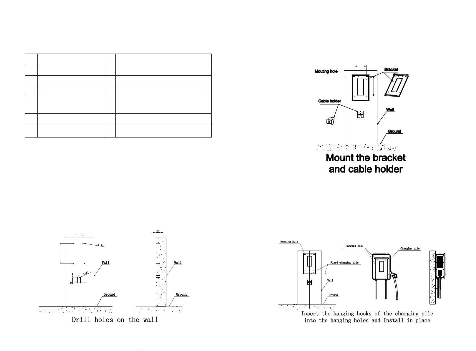
III.Installation and wiring...................................2
IV. Operation instruction and LCD introduction
4.1 Charging mode and operation......................5
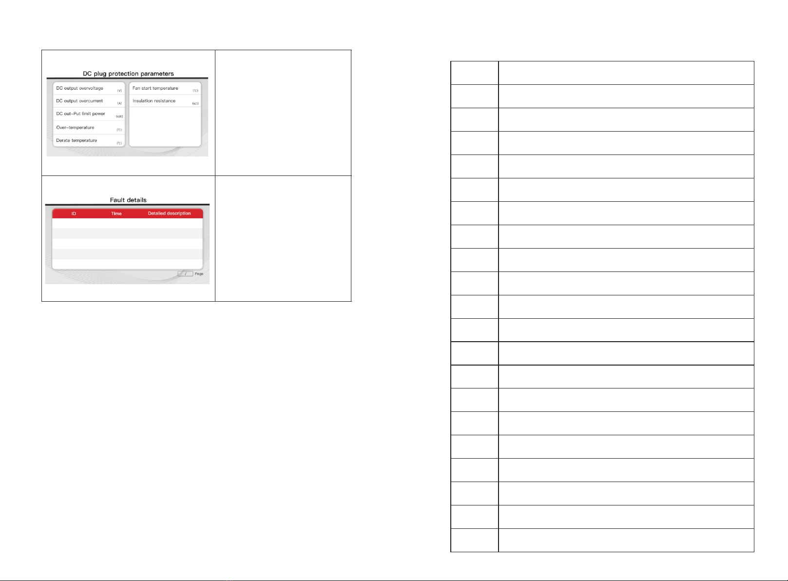
4.2 LCD interface introduction...........................6
4.3 Appendix: Fault code...................................9
V.Specification...............................................10
VI. Appendix
6.1 Electric diagram........................................12
6.2Contact.....................................................14
.
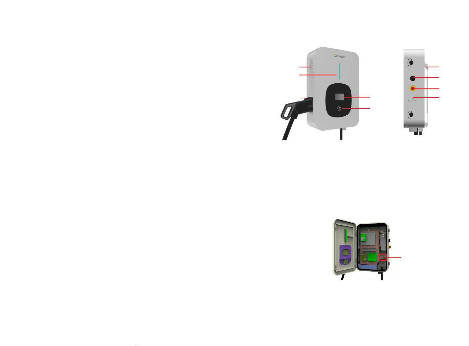
I. Product description
1.Air intake; 6.Mounting bracket ;
2.LED indicator; 7.WIFI/4G antenna;
3.Charging gun holder; 8. Emergency Stop button;
4.HMI; 9.Start or stop button;
5.RFID reader;
Explanation of LED indicators behaviors:
Blue - Standby(The charging equipment can only be used when the blue light lit);
Red Steady on/Flashing - Fault;
Green Steady on - Charging in process;
Green Flashing - Establishing communication;
Yellow Flashing - System initializing.
Internal view and terminal definition
1
5
4
2
3
7
6
8
1
9
1. AC input terminal block. Terminal definition is (①PE;②L2;③L3; ④L3; ⑤N)
from left to right ;
1
2. Terminal block for CT/meter wiring. The terminal definition is:
485A/485B is RS485 terminal for meter connection;
Ia+/Ia- , Ib+/Ib-, Ic+/Ic- is for CT connection;