GROWRILLA RDWC 2.0 User manual

v
MANUAL INSTRUCTION
EN
RDWC
2.0
Growrilla is a 100% Italian brand of
hydroponic farming systems, desi-
gned and made in Italy by growers
for growers.
+39 329 3237168 www.growrillahydroponics.com
info@growrillahydroponics.com
Strada Comunale da Bertolla
all’Abbadia di Stura, 140
10156 Torino - ITALY

Growrilla is a 100% Italian brand of hydroponic farming systems, designed
and made in Italy by growers for growers.
The project stems from a passion for indoor gardening and a common need
for all growers: getting the most out of their plants .
The constant search for information and the desire to experiment with new
techniques has led us to hydroponics, an alternative cultivation method to
the land. Fascinated by the results obtained from the great potential oe-
red, we decided to propose our own system, the result of direct experience
gained over the years, with the aim of oering the grower a functional, easy
to use and high performance product.
Growrilla is not simply a system, first of all it wants to be a resource capable
of providing the grower with the tools necessary to get the most, because
we know that a fast car is not enough to win a race, it is the pilot that makes
the dierence!
Growing with a Growrilla system also means relying on technical and edu-
cational support which, through video tutorials, articles and texts that are
constantly updated, will give you all the information you need to achieve
the results you are looking for!
ABOUT US
ABOUT US
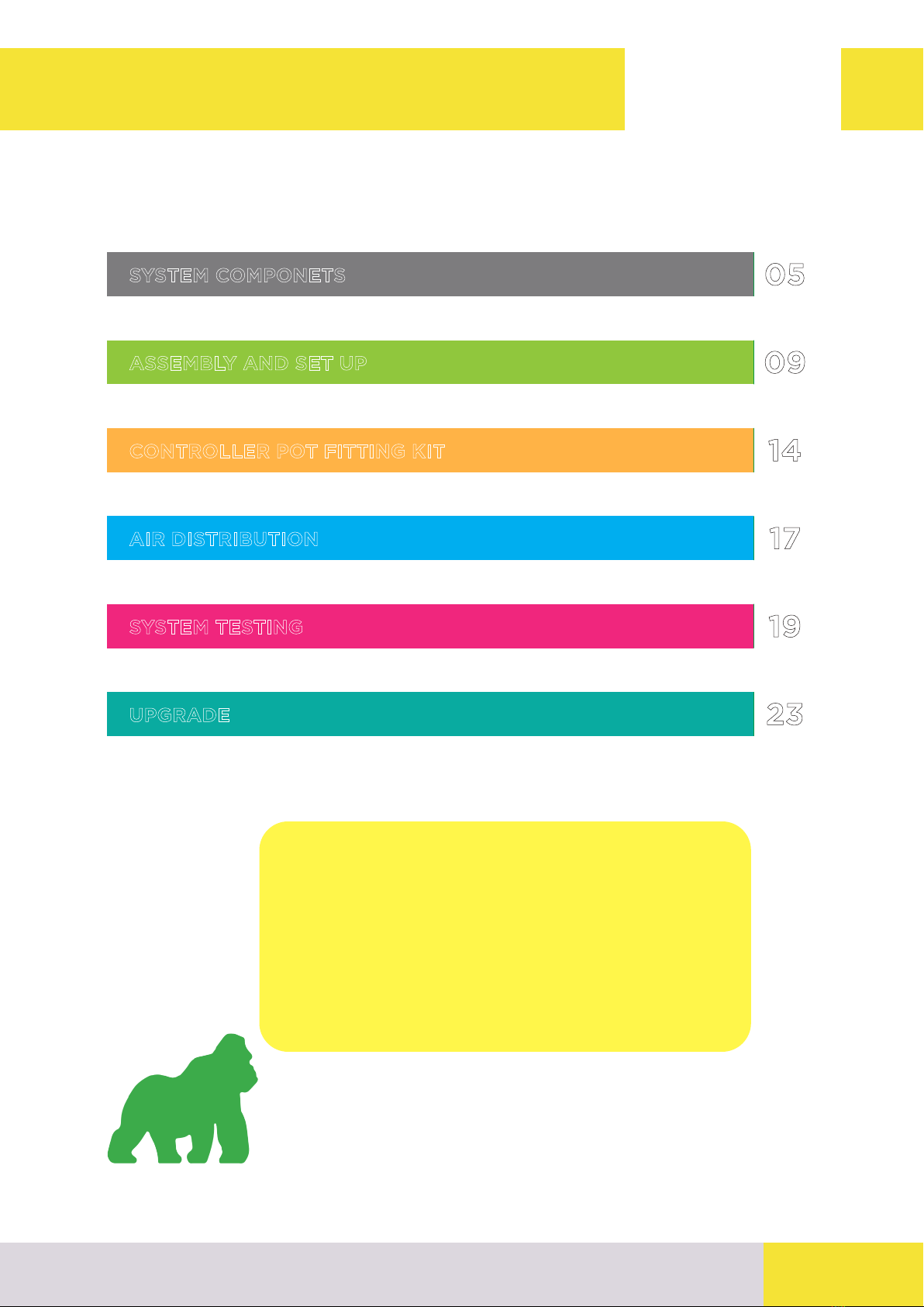
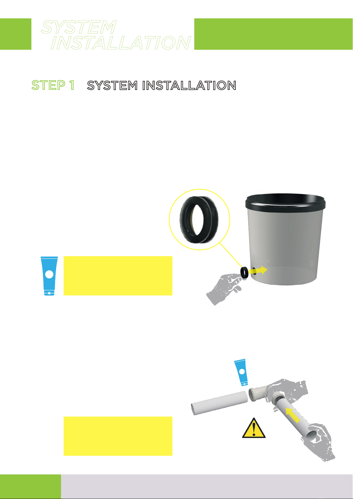
This instruction manual is divided into 5 step, in order to help you for a
right assembly of the system. By closely following these instructions you
will ensure your system is properly installed and ready to grow!
FASE 1. SYSTEM SET UP
FASE 2. CONTROLLER POT FITTING KIT
FASE 3. AIR DISTRIBUTION SYSTEM
FASE 4. TESTING
FASE 5. SYSTEM UPGRADE
INSTRUCTION MANUAL STEPS
1

INFO PAGE
INFO PAGE
INFO PAGE
INFO PAGE
INFO PAGE
INFO PAGE
INFO PAGE
INFO PAGE
INFO PAGE
INFO PAGE
“Hello and congratulations for choo-
sing a Grorilla RDWc system. I’m your
guide who will help you to assemble
and set up your RDWc system. Please
read carefully this manual instruction,
take your time and try to work in a neat
and clean mode, this will ensure to
avoid any issues and make a good job!”
INDEX
23
19
17
14
09
05
UPGRADE
SYSTEM TESTING
AIR DISTRIBUTION
CONTROLLER POT FITTING KIT
ASSEMBLY AND SET UP
SYSTEM COMPONETS
2

LEGENDA
Scan this QRcode to download the manual
directly on your electronic device.
The presence of this symbol indicates to pay the attention to the subject
matter.
Lubricate.
Risk of leakage , pay attention to this step.
Ceck that everything has been done right.
Use pure water.
Rotate and screw.
3

Read carefully this instruction manual before starting to assembly the
system
- Growrilla will NOT be responsible for any damage caused by improper
installation or consequential damage to person or property caused by the
use of this product even if it is determined to be defective.
- Remove the packaging and ceck all the componets from the box. If you
find dameged or missing parts please contact us to info@growrillahydro-
ponics.com
- Ensure that all the electrical devices are intact and free of any damaged
componets
- This system have to work in a protect enviroment, do not expose the
system to cold and rain
NOTE
SAFETY WARNINGS
PACKAGING
The packaging materials of the devices are integrated into
a waste collection, classification and recycling system.
Please dispose of them in the appropriate public containers.
ELECTRICAL / ELECTRONIC PRODUCT
This symbol indicates that once the life cycle is over of the pro-
duct, if you want to dispose of it, it must not be treated as do-
mestic waste but must be delivered to the suitable waste point
for the recycling of electrical and electronic equipment
(RAEE). This product does not contains concentrations of sub-
stances that could cause negative eects on the environment.
RECYCLING / DISPOSAL
4

RC-ATSPC
BULKHEAD ¾”
RC-VALCMF
COMPACT VALVE ¾”
MALE FEMALE
AREA 1 - SYSTEM COMPONENTS
SI-GRC32VDC19
CONTROLLER POT
RDWC 2.0
SI-GRC32VPAS19
GROWING POT
RDWC 2.0
ID-CONGRC19
CONTROLLER
POT LID
SI-GRCCOP191F
GROWING
POT LIDS
ID-NETHD014
NET POT 14CM
RC-GSKGGDN32
32mm WATERPROOF
RUBBER GASKETS
RC-PPBG90322B
32MM ELBOW
PUSH FIT
RC-PPBT90323B
32MM TEE
PUSH FIT
COMPONENTS
GROWRILLA
RC-PG16CM
BARBED FITTING
16X3/4" MALE
RC-PG9016CGM
ELBOW 90 BARBED
FITTIN 16X3/4 FEMALE
RC-FILTECCFFFGM
THREADED
TEE 3/4 FFF
TU-PVC32012
TU-PVC32020
TU-PVC32030
TU-PVC32045
PVC PIPE 32MM
SI-GRC32FVDK
IN LINE FILTER +
VALVE ¾” F
RC-PG16X34GM
BARBED FITTING
FEMALE 16X3/4
TU-PVCGFP16
RETURN HOSE
16MM
SI-GRC32CM016
MALE FITTING ¾”
5

AREA 2 - CONTROLLER POT COMPONENTS
ID-PACHX2500
WATER PUMP
HAILEA HX2500
ID-PACHR1000
ID-PACHR1500
WATER PUMP HAILEA
HR1000 - 1050 L/H
HR1500 - 1400 L/H
RC-FILPRLBC
THREADED
EXTENSION 3/4X1/2
RC-FILMANBCMFGM
THREADED COUPLING
M F 3/4X1/2
SI-GRCHX25GP
WATER PUMP IMPUT
JOINT HX2500
RC-FIL90CCFMGM
THREADED
ELBOW 90 3/4 MF
ID-PAC135TB
ID-PAC140TB
WATER PUMP
EDEN135 - 300/2000L/H
EDEN140 - 500/2800 L/H
RC-FILPRLCMM
THREADED
EXTENSION 3/4
RC-FILMANCGM
THREADED COUPLING
3/4 FEMALE
RC-FIL90CCFMGM
THREADED
ELBOW 90 3/4 MF
SI-GRCVDCIN
SYSTEM INPUT
TJOINT / CHILLER OUT
SI-GRCHX25OUT
SYSTEM OUTPUT
JOINT / CHILLER IN - HX2500
SI-GRC32HROUT
SYSTEM OUTPUT
JOINT / CHILLER IN - HR 135/140
CONTROLLER POT KIT HX2500
CONTROLLER POT KIT HR1000/1500
CONTROLLER POT KIT EDEN 135 - 140
SI-GRC32KVCHX
SI-GRC32KVCHR
SI-GRC32KVC135
KIT CHILLER IN & OUT
6

COMPONENTS
GROWRILLA
AREA 3 - AIR DISTRIBUTION COMPONENTS
T
SILICON AIR HOSE
6X4MM
TU-PVCTH0812
AIR HOSE
12X8MM
PVC AIR HOSE
6X4MM L30CM
PVC64030 t
AIR GASKETS
6MM
RC-PG900305
AIR ELBOW FITTING
3X5MM
RC-PGMU1206U1
AIR MANIFOLD
12X6MM 1 WAYOUT
RC-PGMU1206U2
AIR MANIFOLD
12X6MM 2 WAYOUT
RC-PGSMU1206U4
AIR MANIFOLD
12X6MM 4 WAYOUT
RC-PGSTAP012
AIR LINE
CAP 12MM
ID-POR1002020B
AIR STONE
TU-PEN12050B
TU-PEN12060B
TU-PEN1205100B
AIR DISTRIBUTION PIPE
ARIA 9X12MM
RC-PG9010
BARBED FITTING
ELBOW 10MM
ID-PARV20
AIR PUMP
V-20
ID-PARV30
AIR PUMP
V-30
ID-PARV60
AIR PUMP
V-60
ID-PARET40
AIR PUMP
ET40
t
7

AREA 4 - ADDITIONAL COMPONENTS
ID-VALG12178
FLOAT VALVE
ID-CONTF098
ID-CONTF157
ID-CONTF225
ID-CONTF500
ID-CONTF700
FLEXIBLE TANK
98 LT
SI-GRCTF16MT2
FLEXIBLE TANK
CONNECTION HOSE
SI-GRC32MMBPR
EXTENSION PIPE DELIVERY
MANIFOLD B - L40
SI-GRC32MMAPR
EXTENSION PIPE DELIVERY
MANIFOLD A - L60
TU-PVCGFP16
HOSE
PVC DN16
8

INSTALLATION
SYSTEM
STEP 1 SYSTEM INSTALLATION
RC-GSKGGDN32
a) UNBOX. Place all parts adjacent to the grow area and keep
all the components separately. All the components are divided
by type, this will make it easy to recognize them and will help you
to understand where they have to be used.
c) DELIVERY AND RETURN MANIFOLD. The return
and delivery manifolds are made with PVC pipe and PUSH FIT
FITTING, they are easy to assemble and disassemble. Refer to the
shape of your system to assemble the manifolds, as shown below.
b) GASKETS. Insert the water proof gaskets 50mm inside the
hole at the bottom of the buckets, making sure to put them with
the FRONT writing on the outside of the pots.
LUBRICATE: use a bit of
soap or other lubricant will
help you to insert the
gaskets inside the holes
COUPLING. Apply pres-
sure and twist in the same
motion for optimal fit.
9

RDWC SYSTEM CONFIGURATION
2/3/4 ROWS
RDWC 2 RDWC 9RDWC 4 RDWC 6 RDWC 8
RDWC 18
RDWC 12 RDWC 16
10

RETURN MANIFOLD
DELIVERY AND
2 ROWS 3 ROWS
4 ROWS
SI-GRC32MRA
SI-GRC32MRA
SI-GRC32MMA
SI-GRC32MMB
SI-GRC32MMB
SI-GRC32MRB
11

d) DELIVERY MANIFOLD ASSEMBLY
SI-GRC32MMA
SI-GRC32MMB
L12
L12
L12
L12
L12
L12
L12
L12 L12
L12
L20
L20 L20 L20 L20
L20
L45
RC-PPBG90322B x1
x2
TU-PVC32012
RC-PPBG90322B x1
x1
x3
TU-PVC32012
x1
TU-PVC32045
RC-PPBT90323B
SI-GRC32MRA
RC-PPBG90322B x2
x1
x2
TU-PVC32012
x2
TU-PVC32020
RC-PPBT90323B
SI-GRC32MRB
RC-PPBG90322B x2
x3
x3
TU-PVC32012
x4
TU-PVC32020
RC-PPBT90323B
DELIVERY MANIFOLD A
2/3 ROWS
DELIVERY MANIFOLD B
3/4 ROWS
RETURN MANIFOLD A
2/4 ROWS
RETURN MANIFOLD B
3 ROWS
12

RETURN MANIFOLD
DELIVERY AND
MALE FITTING ¾ Connect the
RETURN MANIFOLT to the VALVE
of the IN LINE FILTER
How to assemble the Return manifold + in line filter whit valve
SI-GRC32MRA RETURN MANIFOLD A
2/4 ROWS
SI-GRC32MRB RETURN MANIFOLD B
3 ROWS
SI-GRC32CM016
RACCORDO
MASCHIO 3/4"
SI-GRC32FVDK
KIT FILTRO CON
VALVOLA 3/4"
13

HOW TO FIT THE
PIPE : PAG 16
GASKET. lubricate the
internal side of the gaskets
and the PVC pipe before
insert them
f) Put all the pots on the floor
of your grow area looking at
the shape of your system ( 2, 3
or 4 rows) and make sure that
the air hole are in the same
position as shown in the pictu-
re below.
g) Now you are able to start to insert the connection pipes inside
the gaskets.
2 ROWS 3 ROWS 4 ROWS
air hole
air hole
rubber hole
14

h) DELIVERY MANIFOLD: connect the controller pot to the first
two growing pot whit the DELIVERY MANIFOLD.
SI-GRC32MMA
System
2 ROWS
(RDWC 2-4-6-8)
System
3 ROWS
(RDWC 9-18)
SI-GRC32MMB
SI-GRC32MMA
SYSTEM
ASSEMBLY
15

INSERT PIPES lubrica-
te pipes and gaskets as
explained before then con-
nect all the growing pots.
DISTANCE BETWEEN POTS:.
the distance between pots can be
adjusted simply sliding the pipes
inside the pots ( please keep mini-
mum 3 cm of pipe inside the the pot)
SI-GRC32MMB
SI-GRC32MMB
h) Growing pot connection.
System
4 ROWS
(RDWC 12 - 16)
TU-PVC32030
16

SYSTEM
ASSEMBLY
i) RETURN MANIFOLD: connect the last two pots at the back of
the system with the relative RETURN MANIFOLD.
System
2/4 ROWS
(RDWC 2-4-6-8-12-18)
System
3 ROWS
(RDWC 9-18)
SI-GRC32MRA
SI-GRC32MRB
17

HX2500
RDWC 2
RDWC 4
RDWC 6
BULKHEAT ¾”. Put the BULKHEAD
inside the hole at the bottom of the
controller pot. Make sure to keep the
Bulkhead gasket inside and tighten the
nut from the outside
STEP 3 CONTROLLER POT KIT
a) Unbox. refer to the type of system you purchased to
identify the right controller pot kit.
b) Water Pump. dierent system size (n. of pots) got dif-
ferent water pump and dierent controller pot kit.
SYSTEM
ASSEMBLY
RC-VALCMF
RC-PG16CGM RC-ATSPC
Screw the WATER
PUMP INPUT JOINT
to the BULKHEAD ¾”
then connect the
water pump to it
SI-GRCHX25GP
CONTROLLER POT KIT HX2500
SI-GRC32KVCHX
18

HR1000
RDWC 8
TRDWC 9
HR1500
RDWC 12
Pompa. Preparare
il kit pompa prima di
alloggiare nel vaso.
SYSTEM
ASSEMBLY
RC-VALCMF
RC-PG16CGM
RC-FILPRLBC
RC-FIL90CCFMGM RC-FIL90CCMF
CONTROLLER POT KIT HR1000 /15000
SI-GRC32KVCHR
RC-FILMANBCMFGM
HOW TO ASSEBLE THE CONTROLLER POT KIT :
1 - connect the water pump to the bulkhead
2 - connect the controller kit to the water pump
19
Table of contents
Other GROWRILLA Farm Equipment manuals