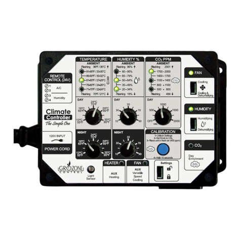
Grozone Control SCC1 User manual

www.grozonecontrol.com
USER GUIDE
SCC1
The Simple One
Climate Controller

TABLE OF CONTENTS
SAFETY NOTICE 3
OUTPUT DESCRIPTIONS 4-5
LED INDICATORS 6-7-8
KNOB SETTINGS 9
CO2 SENSOR CALIBRATION 10
TEMPERATURE CONTROL 11
TEMPERATURE AND HUMIDITY CONTROL 11
HUMIDITY CONTROL 12
CO2 ENRICHMENT 13
WARRANTY & CUSTOMER SERVICE 14-15

SAFETY NOTICE
CAUTION :
SULPHUR VAPORIZATION CAN DAMAGE YOUR CONTROLLER!
In order to protect and ensure a long life to your CO2 controller, it is very
important TO DISCONNECT AND COVER THE CONTROLLER (placing a
plasc bag around the unit) WHILE USING SULPHUR VAPORIZERS IN YOUR
GROW ROOM.
Grozone is able to detect CO2 sniffers that have been contaminated by
sulphur and we reserve the right not to repair these defect units under
warranty. However, we are able to repair your unit at a reasonable cost
in a mely manner.
3
SAFETY NOTICE

OUTPUT DESCRITIONS
4
1A- BASIC 120V OUTPUTS: MAX. 15A, TOTAL OF THE 3 OUTPUTS
FAN
For Day / Night "COOLING ONLY" or
"COOLING AND DEHUMIDIFYING" as
set by Slide Switch.
15A MAX. is used alone.
HUMIDITY
EQUIPMENT
For Day / Night "HUMIDIFYING" or
"DEHUMIDIFYING" as set by the Slide
Switch (and type of equipment used).
15A MAX. if used alone.
CO2
GENERATOR
For Day only "CO2 ENRICHMENT"
using either a tank or a burner.
5A MAX. for inducve load, if used
alone.
1B- LOW VOLTAGE OUTPUTS (REMOTE CONTROL 24V)
These screw terminal interface plays the same role as Grozone LVC1 interface,
visit www.grozonecontrol.com for more details on LVC1)
AIR
CONDITIONING
(A/C)
For Day / Night "COOLING ONLY" or
"COOLING AND DEHUMIDIFYING" as
set by Slide Switch. SCC1 DOES NOT
SUPPLY POWER TO REMOTE A/C.
SCC1 screw terminals are hooked-up
to A/C screw terminal using any type
of wire. Refer to A/C User Guide for
proper connecon.
HUMIDITY
EQUIPMENT
For Day / Night "HUMIDIFYING" or
"DEHUMIDIFYING" as set by Slide
Switch and type of equipment used.
SCC1 DOES NOT SUPPLYPOWER TO
REMOTE HUMIDITY EQUIPMENT
(HE). SCC1 screw terminals are
hooked-up to HE screw terminal.
Refer to HE User Guide for proper
connecon.

INSTALLATION & OPERATION
OUTPUT DESCRITIONS
5
AUX HEATER
For Day / Night "HEATING". User
needs to connect an oponal Remote
Output Box (OB2) with 25-
telephone cable. 15A MAX for this
output only, because it is connected
to a different 120V outlet.
AUX FAN
For Day / Night "COOLING". User
needs to connect an oponal Remote
Output Box (OB2V) with 25-
telephone cable. OB2V works as a
Remote TV1 or TV2 Grozone Variable
Speed Fan Controllers. Fan speed will
vary according to the amount of heat
to exhaust.
1C- AUX 120V OUTPUTS
(oponal Output using remote Output Boxes – See Advanced User Guide for
more details)

INSTALLATION & OPERATION
LED INDICATORS
6
2A- TO SHOW AMBIENT TEMPERATURE, HUMIDITY AND CO2 PPM
TEMPERATURE HUMIDITY CO2
96°F AND MORE 96% AND MORE 2001 PPM
AND MORE
91°F TO 95°F 80% TO 95% 1700 TO
2000 PPM
86°F TO 90°F 65% TO 79% 1400 TO
1700 PPM
81°F TO 85°F 50% TO 64% 1100 TO
1400 PPM
76°F TO 80°F % 35% TO 49% 800 TO
1100 PPM
71°F TO 75°F 20% TO 34% 500 TO
800 PPM
70°F AND LESS 19% AND LESS 499 PPM
AND LESS
Example of LEDs indicang a temperature of 81 to 85°F, a humidity level of 35% to
49% and a CO2 level of 1700 to 2000 ppm.
All the LED indicator possibilies are:

LED INDICATORS
7
2B- TO SHOW SENSOR WARM-UP PERIOD
TEMPERATURE HUMIDITY CO2
Not applicable
Values are valid
from Power ON.
Not applicable
Values are valid
from Power ON.
30-Sec Warm-Up
Time at Power Up:
CO2 Sensor needs
30-sec warm up
before reading
valid values.
TEMPERATURE HUMIDITY CO2
Temperature
Sensor Fail
Humidity
Sensor Fail
CO2 Sensor Fail
2C- TO SHOW SENSOR FAILURES (TEMPERATURE, HUMIDITY OR CO2)
Refer to Advanced User Guide for detailed informaon about the acons taken
when a top priority Sensor Failure occurs.
OUTPUTS Output
Indicator OFF
Output
Indicator ON
Output Indicator
FLASHING
Output relay IS
NOT acvated,
receptacle DOES
NOT supply
120V.
Output relay IS
acvated, recepta-
cle DOES supply
120V.
Output relay acvaon is
pending, because at least
one of these condions is
met:
1. high priority CO2 Output
is ON (factory seng).
2. 10-min. ON-DELAY is
counng down aer CO2
output has turned OFF.;
3. Low Temp Limit has been
reached only if
Cool&Dehum is set.
2D- TO SHOW OUTPUT STATES

LED INDICATORS
8
OUTPUTS Output
Indicator OFF
Output
Indicator ON
Output Indicator
FLASHING
Output relay IS
NOT acvated,
receptacle DOES
NOT supply 120V.
Output relay IS
acvated, recep-
tacle DOES supply
120V.
Will never flash,
not implemented.
Output relay IS
NOT acvated,
receptacle DOES
NOT supply 120V.
Output relay IS
acvated, recep-
tacle DOES supply
120V
Output relay acvaon is pend-
ing, because at least one of
these condions is met:
1.High Temp Limit has been
reached;
2. Empty Tank: High Temp Limit
reached twice in a row OR 30-
minute meout elapsed WHILE
CO2 level is sll low.
3. High priority FAN Output is
ON (alternate seng).
Output Box OB2 is
NOT connected
OR
Output Box OB2 IS
NOT acvated,
receptacle DOES
NOT supply 120V.
OB2 relay IS ac-
vated, Output
Box receptacle
DOES supply
120V
Note: Indicator
will remain ON if
OB2 is discon-
nected while ac-
vated.
Indicator will not
turn ON anymore
once it turns OFF
Will never flash,
not implemented.
Output Box OB2V
is NOT connected
OR
OB2V is forced to
OFF during a Tem-
perature Sensor
Failure.
Normal Opera-
on OB2V is DIM-
MING Fan Speed
(can be fully OFF,
fully ON or
DIMMED as per
sengs)
Will never flash,
not implemented.

CO2 SENSOR CALIBRATION
KNOB SETTINGS
9
3A- KNOB RANGES
DAY AND NIGHT TEMPERATURE SETTINGS:
55°F to 95°F / 13°C to 35°C
DAY AND NIGHT HUMIDITY SETTINGS:
10% to 90°F
DAY CO2 SETTING:
OFF, 400 TO 2000 PPM
(Note: all value below 400 ppm will be set to 400 ppm)
For CALIBRATION, refer to Secon 4.
3B- LOCK SETTINGS
· PLACE SLIDE SWITCH TO UNLOCK (TOP PO-
SITION) TO SET YOUR KNOB VALUES.
· PLACE SLIDE SWITCH TO LOCK (BOTTOM
POSITION) TO SAVE YOUR KNOB VALUES.
IMPORTANT NOTICE: ONCE LOCKED, VALUES
WILL BE PRESERVED EVEN THOUGH KNOBS ARE
ROTATED INADVERTENTLY.
IMPORTANT NOTICE: DO NOT FORGET TO UN-
LOCK BEFORE CHANGING YOUR SETPOINTS.

10
CO2 SENSOR CALIBRATION
4- CO2 SENSOR CALIBRATION
1- Place the LOCK/UNLOCK Slide Switch to the UNLOCK Posion
(Top posion).
2- Set the CO2 Day Setpoint to the CAL posion (fully counter clock-
wise).
3- In order to get a VALID CALIBRATION, the unit must be placed
temporarily outdoors or in fresh air, where natural CO2 level is
close to 400 ppm.
4- Push and hold buon for 10 seconds: the 3 CO2 Ambient LED In-
dicators will blink every second 10 mes, then the Indicators will
remain LIT unl you let the pushbuon go.
· If the CALIBRATION is good, the indicators will blink 4 mes.
· If the CALIBRATION is bad, the indicators will blink only once.
The unit returns to Normal Operaon.
CO2 Sensor Calibraon is performed in 4
easy steps.

11
TEMPERATURE CONTROL WITH FAN
TEMPERATURE & HUMIDITY CONTROL WITH FAN
To use this mode, you connect your cooling Fan into
the FAN 120V Output, set the Slide Switch to “Cooling”
posion.
5- Temperature control with fan (and Oponal Heater)
To use this mode, you connect your cooling Fan into the
FAN 120V Output, set the Slide Switch to “Cooling & Dehu-
midifying” posion.
6– Temperature and Humidity control with fan (and Oponal Heater)
Safety Heang Range
(oponal)
Cooling Range
SP-8° F SP-2° F SP+2° F
Heater Start Up Heater Stop
Fan Stop Fan Start Up
Day or Night
Setpoint (SP)
Temperature
Low Temp Limit Set
Uncondional Fan Stop
Unwanted Cooling Range
with Dehumidifying
(air is cold and humid)
Cooling Range
(air is coll and dry)
Low Temp Limit Reset
Fan resumes Cooling &
Dehum.
Temp. Setpoint (TS)
Fan Stop if
dry enough Fan Stop Up
Safety Heang Range
(oponal)
Temperature
TS-8° F TS-6° F TS-2° F TS+2° F
Dehumidifying Range
HS HS+4%
Humidity
Dehumidifier
Stop
Dehumidifier
Start Up
Humidity Setpoint (HS)

12
To use this mode, you connect your Humidity Equipment (Humidifier or
Dehumidifier) into the HUMIDITY 120V Output, set the Slide Switch to ei-
ther “Humidifying” or “Dehumidifying” according to your equipment type.
HUMIDIFYING - SLIDE SWITCH TO TOP POSITION
DEHUMIDIFYING - SLIDE SWITCH TO BOTTOM POSITION
Humidifying Range
Humidity
Humidifier
Start Up
Humidifier
Stop
HS-4% HS
Humidity Setpoint (HS)
Dehumidifying Range
HS HS+4%
Dehumidifier
Stop
Dehumidifier
Start Up
Humidity
Humidity Setpoint (HS)
HUMIDITY CONTROL
7– Humidity Control with a Humidifier or Dehumidifier

To use this mode, you connect your CO2 Generator into the CO2 120V
Output. CO2 Enrichment will work during the DAY ONLY.
CO2 ENRICHMENT
CO2 PPM Range
CO2 PPM
CS-200 CS
Burner Star Up Burner Stop
CO2 Setpoint (CS)
Normal Cooling
Range
Unwanted Heang caused by Burner
while Fan is Stopped by High Priority
CO2
Temperature
DTS-2° F DTS+2° F DTS+10° F
High Temp Limit Reset
Burner may resume
High Temp Limit set
Uncondional
Burner Stop
13
8– CO2 Enrichment with burner or a tank

WARRANTY & CUSTOMER SERVICE
DO YOU HAVE A PROBLEM WITH YOUR CONTROLLER ? PLEASE READ
THESE INSTRUCTIONS CAREFULLY AND SAVE THEM FOR FUTURE
REFERENCE.
1. I think my controller is damaged, or it simply does not work as
indicated in the user guide, what should I do?
· Please refer to the troubleshoong steps. Follow these instrucons
carefully, step by step. The controller should work as described in the
“Expected results” column of the Complete Troubleshoong Guide.
Do you need assistance on execung the Troubleshoong steps?
1. Contact us at 1-855-262-1800
2. Send us an EMAIL at ser[email protected]
3. VISIT our Technical Support Center at
www.grozonecontrol.com/techsupport.html
Technical Support is available Monday through Friday, from 8:00 AM to
8:00 PM, Eastern Time.
WARRANTY & CUSTOMER SERVICE
14

2. I’ve been through the troubleshoong steps. What do I do if I meet a
problem at any of these steps? Is my product covered by the
WARRANTY?
· Grozone controllers are covered by a 3-year warranty (*). We will
replace any DAMAGED PRODUCT WITH A BRAND NEW PRODUCT.
· Covered or not covered? We do not authorize the replacement of fully
working products nor altered (tampered) products. The Troubleshoong
steps will help you idenfy a damaged product. Do not hesitate to
contact us or contact your retailer to make sure the controller is not fully
working or damaged before returning it to the store.
· My product is not fully working or damaged, I want a replacement unit:
in order to get a replacement product, you MUST return all modules
and applicable accessories to the retailer. To avoid being charged for
the accessories, be sure to include all pieces. Thanks for your
cooperaon.
· Any Grozone Control product that is returned with obvious signs of user
neglect will not be covered by the warranty. Grozone Control exercises
the right to make final decisions in these maers.
(*)The warranty period begins from the date of purchase at the retail level.
The retailer/consumer must keep their proof of sale/purchase. Otherwise,
Grozone Control will consider the manufacturing date to apply the warranty
coverage.
IMPORTANT MESSAGE TO RETAILERS
Retailers must call Grozone Control to get authorisaon to replace the
defecve product and a RMA number.
1-855-262-1800
WARRANTY & CUSTOMER SERVICE
15

NOTE

NOTE


GUIDE D’UTILISATION
SCC1
The Simple One
Contrôleur de climat
www.grozonecontrol.com

TABLE DES MATIÈRES
NOTICE DE SÉCURITÉ 3
DESCRIPTIONS DES SORTIES 4-5
INDICATEURS DELs 6-7-8-9
BOUTONS ET AJUSTEMENTS 10
CALIBRATION DU CAPTEUR DE CO2 11
CONTRÔLE DE LA TEMPÉRATURE 12
CONTRÔLE DE LA TEMPÉRATURE/HUMIDITÉ 12
CONTRÔLE DE L’HUMIDITÉ 13
ENRICHISSEMENT DE CO2 14
SERVICE À LA CLIENTÈLE ET GARANTIE 15-16
Table of contents
Languages:
Other Grozone Control Controllers manuals
Grozone Control
Grozone Control SCO2 User manual

Grozone Control
Grozone Control CO2D User manual

Grozone Control
Grozone Control SCO2 User manual

Grozone Control
Grozone Control HT2 User manual

Grozone Control
Grozone Control TV12 User manual

Grozone Control
Grozone Control Temp-3 User manual

Grozone Control
Grozone Control TV2 User manual

Grozone Control
Grozone Control TV2 User manual

Grozone Control
Grozone Control The Simple One CLIMATE CONTROLLER Assembly instructions
Grozone Control
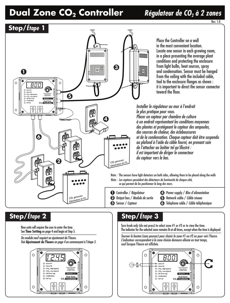
Grozone Control Dual Zone CO2 Controller User manual