Grozone Control SCO2 User manual

www.grozonecontrol.com
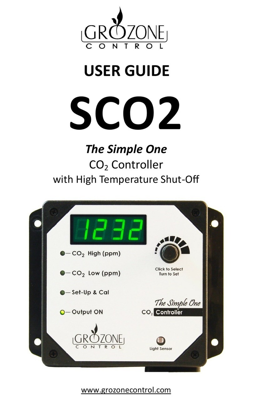
USER GUIDE
SCO2
The Simple One
CO
2
Controller
with High Temperature Shut-Off

SAFETY NOTICE 3
INSTALLATION & OPERATION 4-5-6-7
CO
2
SENSOR CALIBRATION 8-9
QUICK TROUBLESHOOTING GUIDE 0-
ERROR CODES 2
COMPLETE TROUBLESHOOTING GUIDE 3- 4- 5- 6
WARRANTY & CUSTOMER SERVICE 7- 8
PRODUCT DETAILS 9
TABLE OF CONTENTS

s
3
SAFETY NOTICE
CAUTION :
SULPHUR VAPORIZATION CAN DAMAGE YOUR CONTROLLER!
In order to protect and ensure a long life to your CO
2
controller it is very
important TO DISCONNECT AND COVER THE CONTROLLER (placing a
plastic bag around the unit) WHILE USING SULPHUR VAPORIZERS IN YOUR
GROW ROOM.
Grozone is able to detect CO
2
sniffers that have been contaminated by
sulphur and we reserve the right not to repair these defect units under
warranty. However we are able to repair your unit at a reasonable cost
in a timely manner.
3

Step
Connecting the equipment
Securely mount controller on a wall at plant level.
Connect one end of the detachable power cord into a 120 V outlet and the
second end into the power input connector on the left side of the
controller .
The controller warms up for 30 seconds before displaying a valid CO
2
reading.
Plug the CO
2
generator into the 120V outlet also on the left side of the
controller .
INSTALLATION & OPERATION
4

INSTALLATION & OPERATION
Click knob and rotate to set high ppm value.
Step 2
Setting high limit
Step 3
Setting low limit
Click knob and rotate to set low ppm value.
INSTALLATION & OPERATION
5

INSTALLATION & OPERATION
Step 4
Setting operating mode
Click knob and rotate to select your operating mode.
F : CO
2
enrichment - day only F 4 : CO
2
exhausting - day only
F 2 : CO
2
enrichment - night only F 5 : CO
2
exhausting - night only
F 3 : CO
2
enrichment - day & night F 6 : CO
2
exhausting - day & night
Step 5
Setting temperature unit
Click knob and rotate to select Celsius (CELS) or Fahrenheit (FAHr).
Default is Celsius.
INSTALLATION & OPERATION
6

Step 6
Setting high temperature limit
Click knob and rotate to set high temperature limit from 21°C to 49°
C (70°F to 120°F). Default is 35°C (95°F) displayed as H 35 (H 95).
To disable the high temperature shut-off function turn knob clock-
wise beyond 49°C (120°F) until « OFF » appears on screen.
INSTALLATION & OPERATION
End of settings
TO EXIT and RETURN TO NORMAL OPERATION click knob TWICE.
TO CALIBRATE THE CO2 SENSOR click knob only ONCE and refer to the
instructions on next pages.
Controller Operation
Your controller is set and ready to operate when the top 3 light indicators
are off. According to selected operation mode the controller will either
exhaust CO2 from or inject CO2 into your grow room and maintain the CO2
level between the user defined high and low limits (steps 2 and 3).
When using a gas burner as CO2 generator you are likely to experience high
temperature conditions that can damage your crop. With high temp shut-
off function enabled the controller will defeat the burner if room tempera-
ture reaches the high temperature limit (step 6). CO2 Operation resumes
automatically when room temperature cools down by 3°C (5°F).
Displaying actual CO2 and temperature: in order to switch between
actual CO2 and temperature values on screen rotate knob clockwise
for temperature or counter clockwise for CO2.
7
IMPORTANT NOTICE:
This step is not required for a new unit (factory calibrated). Verify CO
2
sen-
sor precision by exposing your unit to outdoor air every 6 months (correct
value stands between 300 and 500 ppm).
If you need to calibrate the sensor please follow these instructions. At any
time before the last step the calibration procedure may be cancelled
causing the controller to return to normal operation.
CO
2
SENSOR CALIBRATION
Steps
IMPORTANT : Before beginning the calibration bring the con-
troller outdoor (fresh air being use as a reference) and wait un-
til the reading is stable (2-3min). If the value on the screen is
around 350 to 450 ppm YOU DO NOT NEED TO RECALIBRATE
YOUR UNIT.
1 Click knob repeatedly until "Set-Up & Cal" indicator turns ON.
2
Press knob and keep it pressed for about 5 seconds until "Set
Up & Cal" light indicator begins to flash and "CAL" appears on
screen.
3
Let knob go "CO
2
" and "CAL" appears on the screen alternately
(blinking).
CO
2
SENSOR CALIBRATION
8

CO
2
SENSOR CALIBRATION
4
Click knob again then "CAL" and "400" appears on the screen al-
ternately (blinking).
5
TO CALIBRATE: press knob and hold at least 5 seconds until "CAL"
shows up on the screen (not blinking) then let knob go.
IMPORTANT : If you "click" the knob without holding for 5
seconds you will exit WITHOUT calibrating.
6
The calibration process only takes a few seconds. When com-
pleted "CAL" and "GOOD" appear on the screen alternately
(blinking) for 5 seconds then the controller returns to normal op-
eration.
IMPORTANT : You MUST see "GOOD" on the screen at the end of
the calibration process. If not the calibration has FAILED. You
need to go back to step 1.
CO
2
SENSOR CALIBRATION
9

Output
10

Turn the knob
fully CW. At Max
temps (off)
Value
11
Output

ERROR CODES
SCO2 Alarm and Error Meanings
Alarm/Error # Description Displayed on
Screen
Error
CO
2
Sensor problem:
Turn power off and retry. If problem
persists call Grozone Control at :
1-855-262-1800
or email at :
service@grozonecontrol.com
Er.
Error 8
Memory corruption problem :
All settings have been reset to factory
settings. You need to go through the
entire menu and re-enter every
settings on your controller. If problem
persists call Grozone Control at :
1-855-262-1800
or email at :
service@grozonecontrol.com
Er.8
Alternately
with sensor
values
Factory Default Reset:
Disconnect the controller push and hold the knob down while recon-
necting the controller: "rrrr" will show on the display. All settings have
been reset to factory settings.
ERROR CODES
12

COMPLETE TROUBLESHOOTING GUIDE
CO
2
Controller
SCO2
1 – Before you start
2 – Test
***IMPORTANT: READ AND FOLLOW THESE INSTRUCTIONS BEFORE
STARTING THE TEST.
•
CONNECT A LOAD INTO THE OUTLET ON THE LEFT SIDE OF THE
CONTROLLER (lamp or fan).
•
LIGHTING CONDITION: perform this test in a room with enough light for
the controller to detect a DAY condition.
•
PERFORM THIS TEST IN A ROOM WHERE THE CO
2
LEVEL IS LOW (UNDER
1000 PPM).
STEP HANDLING AND TEST DESCRIPTIONS EXPECTED RESULTS
1 Plug the controller power cord into any
120V outlet or power bar.
The screen shows a 30
seconds countdown
after a short
introduction displaying
the name of the
product and the
revision number. Wait
until the countdown
2 After 30 seconds the controller will
indicate the CO
2
level in your room.
An appropriate value
should stand between
400 and 1000 ppm. It
might be higher if your
room is not ventilated
enough. CALIBRATION
will be verified at step
0.
COMPLETE TROUBLESHOOTING GUIDE
13

COMPLETE TROUBLESHOOTING GUIDE
STEP HANDLING AND TEST DESCRIPTIONS EXPECTED RESULTS
3
Click knob once.
Turn knob both ways and set value to
4500 ppm (needed for step 5).
The CO
2
High (ppm)
light indicator lights up
and the display
indicates the CO
2
high
setpoint (the default
value is 1500 ppm).
This value on screen
may be adjusted by
4 Click knob three times. Wait 5 seconds.
The SCO2 goes back to
reading mode. All light
indicators are off
except Output On.
5
Click knob three times. Turn knob in both
directions to change the value on screen
between F 3 and F 4 repeatedly.
The Output ON
indicator will turn off
when F 4 is set and
will turn back on when
F 3 is set.
F 4 = Output OFF
F 3 = Output ON
The load connected to
the controller should
turn on and off along
with the Output ON
light indicator.
IMPORTANT: The CO
2
High (ppm) has to be
set at 4500 ppm to
perform this step
successfully.
COMPLETE TROUBLESHOOTING GUIDE
14

COMPLETE TROUBLESHOOTING GUIDE
STEP HANDLING AND TEST DESCRIPTIONS EXPECTED RESULTS
6
Turn the knob to set value to F .
Click knob one last time.
The first 3 light
indicators will be off
and the display
indicates the CO
2
level
in the room. The
Output ON indicator
will turn ON.
7
COVER the day-night detector (Light
Sensor) with the palm of your hand or
some black electric tape. Using only one
finger will not cover the light sensor
appropriately and daylight will be
detected.
The Output ON light
indicator and the load
plugged into the outlet
will turn off after 6 to 8
seconds when the
night condition is
detected.
8 UNCOVER the light sensor and wait for 6
to 8 seconds.
The Output ON
indicator will turn ON
when day condition is
detected.
9
Blow softly into the air intake (lower
right corner of the module) through the
air filter.
The CO
2
concentration
will gradually increase
up to 5000 ppm and
above. The Output ON
indicator will turn off
and the screen will
show « OVER » and «
5000 » alternately.
COMPLETE TROUBLESHOOTING GUIDE
15

COMPLETE TROUBLESHOOTING GUIDE
STEP HANDLING AND TEST DESCRIPTIONS EXPECTED RESULTS
10
To verify if the CO
2
sensor calibration is
required bring the controller outdoor
and wait until the reading is stable (2-3
min). AVOID BREATHING NEAR THE
CONTROLLER.
IF REQUIRED you will find the
calibration procedure on page 5-6.
The CO
2
ppm value on
the screen should be
between 350 and 450
ppm, even up to 500
ppm in urban
surroundings. In this
case, your controller
DOES NOT NEED
calibration.
Note: The built-in CO
2
sensor is precise to +/-
75 ppm (industry
standard) meaning
that two or more
controllers in the same
room are likely to
indicate different ppm
values showing
variation between
them of up to 150
ppm. THIS IS NORMAL
and no action is
required. If the
variation between
readings is beyond 150
-200 ppm one of them
is likely to require a
calibration. Be aware
that a difference of 100
ppm has insignificant
effect on plants.
COMPLETE TROUBLESHOOTING GUIDE
16

WARRANTY & CUSTOMER SERVICE
DO YOU HAVE A PROBLEM WITH YOUR CONTROLLER ? PLEASE READ
THESE INSTRUCTIONS CAREFULLY AND SAVE THEM FOR FUTURE
REFERENCE.
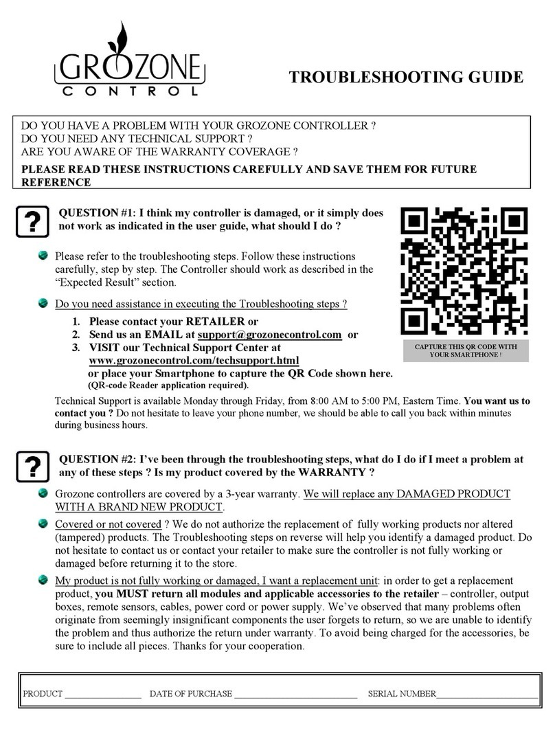
. I think my controller is damaged, or it simply does not work as
indicated in the user guide, what should I do?
•
Please refer to the troubleshooting steps. Follow these instructions
carefully step by step. The controller should work as described in the
“Expected results” column of the Complete Troubleshooting Guide.
Do you need assistance on executing the Troubleshooting steps?
. Contact us at -855-262- 800
2. Send us an EMAIL at service@grozonecontrol.com
3. VISIT our Technical Support Center at
www.grozonecontrol.com/techsupport.html
Technical Support is available Monday through Friday from 8:00 AM to
8:00 PM Eastern Time.
WARRANTY & CUSTOMER SERVICE
17

2. I’ve been through the troubleshooting steps. What do I do if I meet a
problem at any of these steps? Is my product covered by the
WARRANTY?
•
Grozone controllers are covered by a 3-year warranty (*). We will
replace any DAMAGED PRODUCT WITH A BRAND NEW PRODUCT.
•
Covered or not covered? We do not authorize the replacement of fully
working products nor altered (tampered) products. The Troubleshooting
steps will help you identify a damaged product. Do not hesitate to
contact us or contact your retailer to make sure the controller is not fully
working or damaged before returning it to the store.
•
My product is not fully working or damaged I want a replacement unit:
in order to get a replacement product you MUST return all modules
and applicable accessories to the retailer. To avoid being charged for
the accessories be sure to include all pieces. Thanks for your
cooperation.
•
Any Grozone Control product that is returned with obvious signs of user
neglect will not be covered by the warranty. Grozone Control exercises
the right to make final decisions in these matters.
(*)The warranty period begins from the date of purchase at the retail level.
The retailer/consumer must keep their proof of sale/purchase. Otherwise
Grozone Control will consider the manufacturing date to apply the warranty
coverage.
IMPORTANT MESSAGE TO RETAILERS
Retailers must call Grozone Control to get authorisation to replace the
defective product and a RMA number.
-855-262- 800
WARRANTY & CUSTOMER SERVICE WARRANTY & CUSTOMER SERVICE
18

PRODUCT DETAILS
Operation and Specifications
Output 120V 5A max.
Input 120V 60Hz 10A max.
CO
2
sensor : 0-5000PPM
Day and night detection with photocell
Digital display
PRODUCT DETAILS
19

Other manuals for SCO2
1
Table of contents
Languages:
Other Grozone Control Controllers manuals

Grozone Control
Grozone Control TV2 User manual

Grozone Control
Grozone Control CO2D User manual

Grozone Control
Grozone Control TV2 User manual

Grozone Control
Grozone Control HT2 User manual

Grozone Control
Grozone Control SCO2 User manual

Grozone Control
Grozone Control TV12 User manual

Grozone Control
Grozone Control Temp-3 User manual

Grozone Control
Grozone Control The Simple One CLIMATE CONTROLLER Assembly instructions

Grozone Control
Grozone Control Dual Zone CO2 Controller User manual

Grozone Control
Grozone Control SCC1 User manual