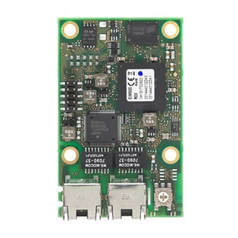
Grundfos CIM 100 User manual
Other Grundfos Control Unit manuals

Grundfos
Grundfos CIM 500 User manual
Grundfos
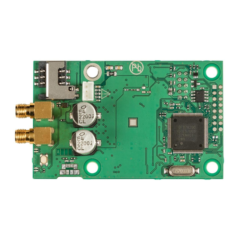
Grundfos TP User manual
Grundfos
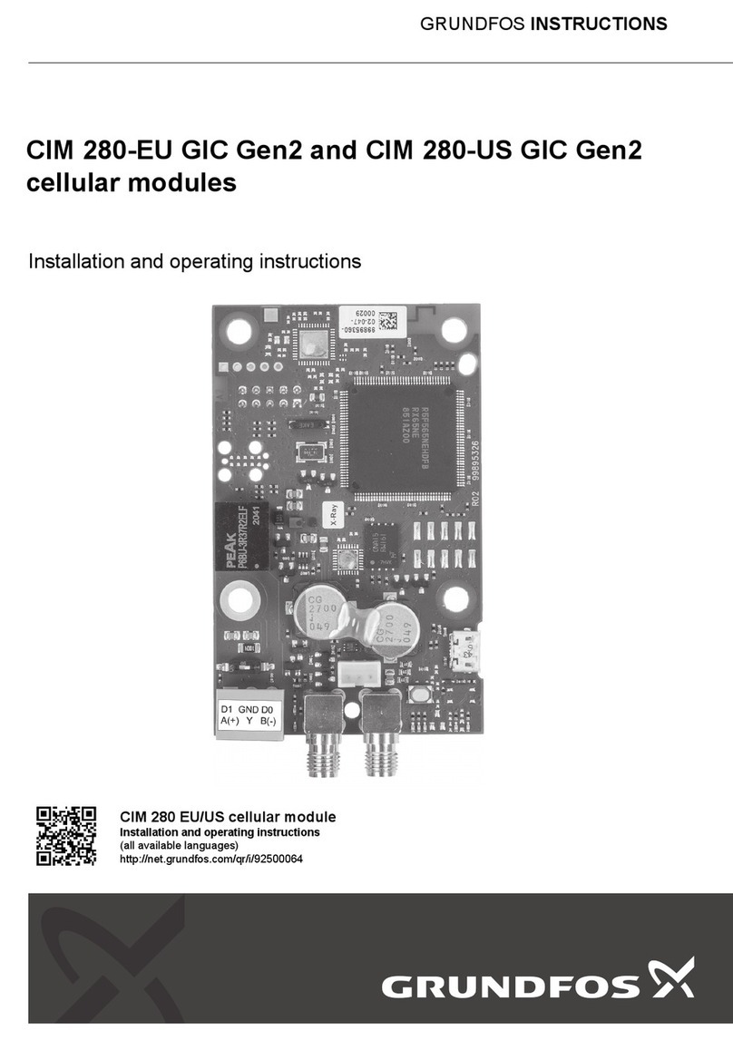
Grundfos CIM 260 User manual
Grundfos
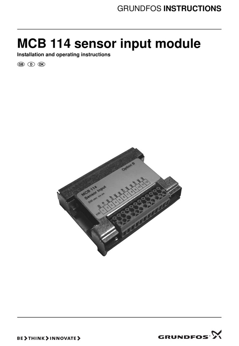
Grundfos CIM 280-EU GIC Gen2 User manual
Grundfos
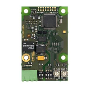
Grundfos MCB 114 User manual
Grundfos
Grundfos CIM 200 User manual

Grundfos
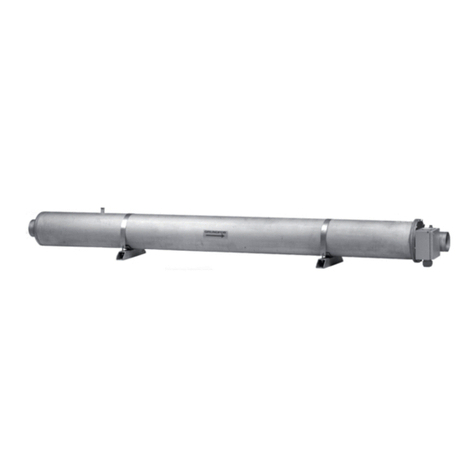
Grundfos OHJEET CIM 500 User manual
Grundfos
Grundfos BM User manual

Grundfos
Grundfos CIM 500 User manual
Grundfos
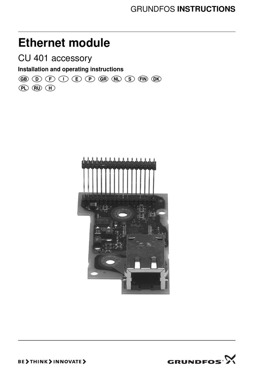
Grundfos CU 401 User manual

Grundfos
Grundfos PC Tool CU 300 User manual
Grundfos
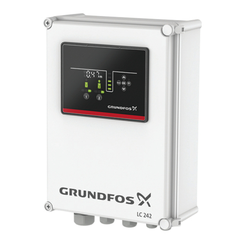
Grundfos LC 23 Series Operating instructions
Grundfos
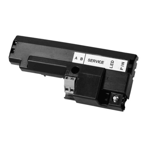
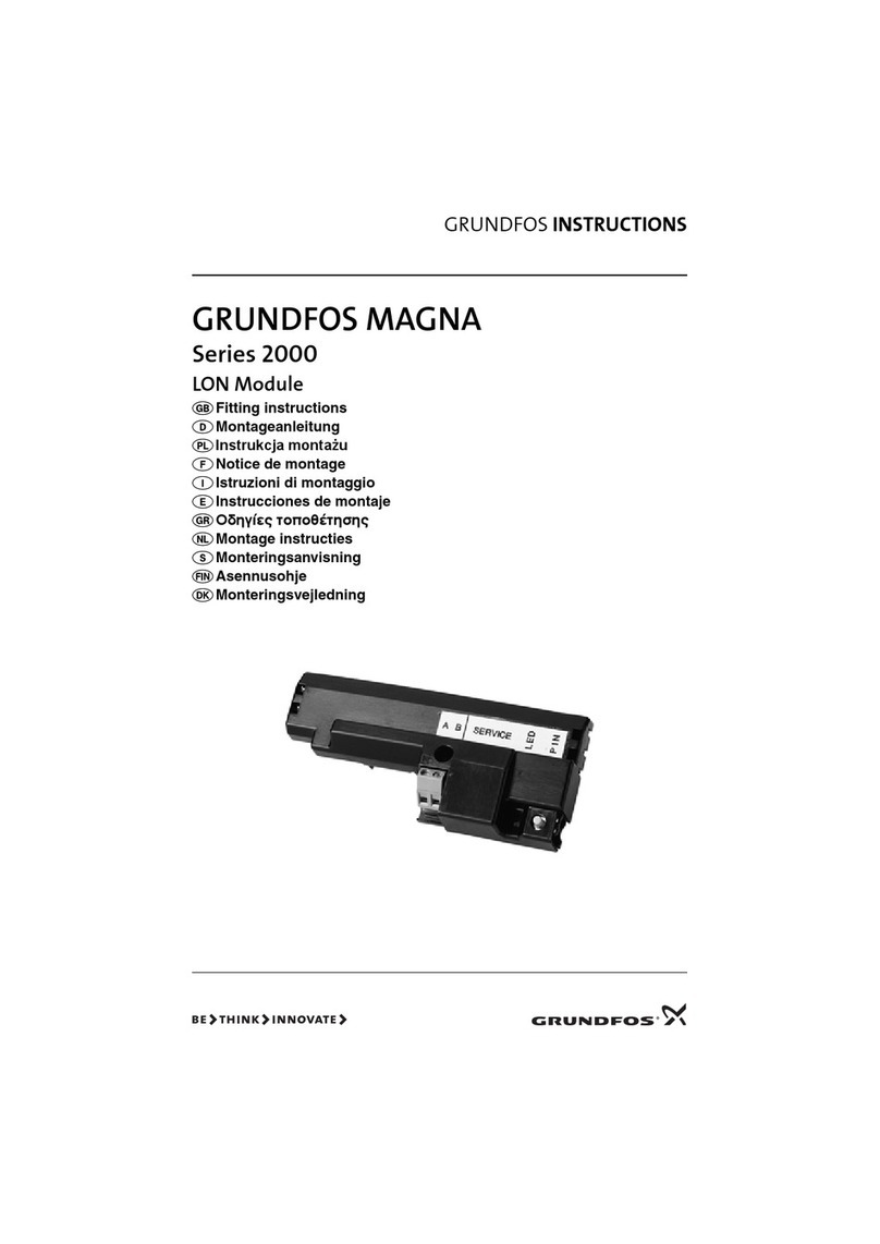
Grundfos MAGNA 2000 Series User manual
Grundfos
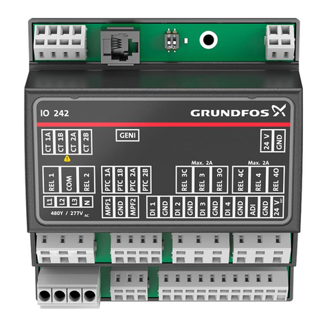
Grundfos MAGNA 2000 Series User manual
Grundfos
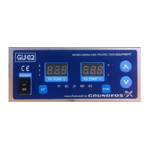
Grundfos IO 242 User manual
Grundfos
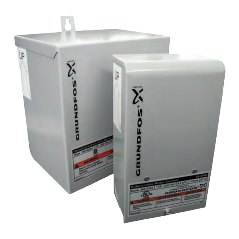
Grundfos KJ1 GU02 User manual
Grundfos
Grundfos SA Series User manual
Grundfos
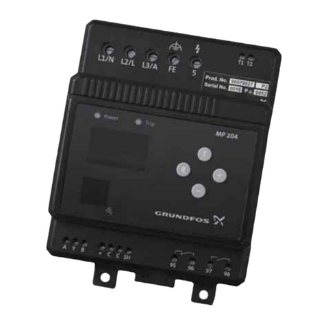
Grundfos MP 204 User manual

Grundfos
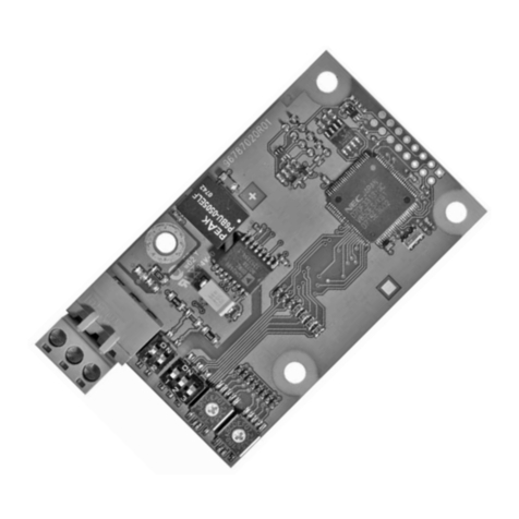
Grundfos CIM 260 User manual
Grundfos
Grundfos CIM 3 Series User manual
Popular Control Unit manuals by other brands

Festo
Festo Compact Performance CP-FB6-E Brief description

Elo TouchSystems
Elo TouchSystems DMS-SA19P-EXTME Quick installation guide

JS Automation
JS Automation MPC3034A user manual

JAUDT
JAUDT SW GII 6406 Series Translation of the original operating instructions

Spektrum
Spektrum Air Module System manual

BOC Edwards
BOC Edwards Q Series instruction manual

KHADAS
KHADAS BT Magic quick start

Etherma
Etherma eNEXHO-IL Assembly and operating instructions

PMFoundations
PMFoundations Attenuverter Assembly guide

GEA
GEA VARIVENT Operating instruction

Walther Systemtechnik
Walther Systemtechnik VMS-05 Assembly instructions

Altronix
Altronix LINQ8PD Installation and programming manual
