GSi iS PC522142-C4 Setup guide

S
A
IN
O
P
M
A
M
A
FETY
STALLATI
O
P
ERATION
A
INTENA
N
M
AN
U
O
N
N
CE
U
AL
B
u
O
w
w
u
cket
No.
R
e
9575N.
O
maha,Nebra
(402)
w
w.intersys
t
Elev
a
PC522
1
e
vised201
109
th
Ave.
ska68142
330‐1500
t
ems.net
a
tor
1
42‐C4
0‐01‐15

1
TABLE OF CONTENTS
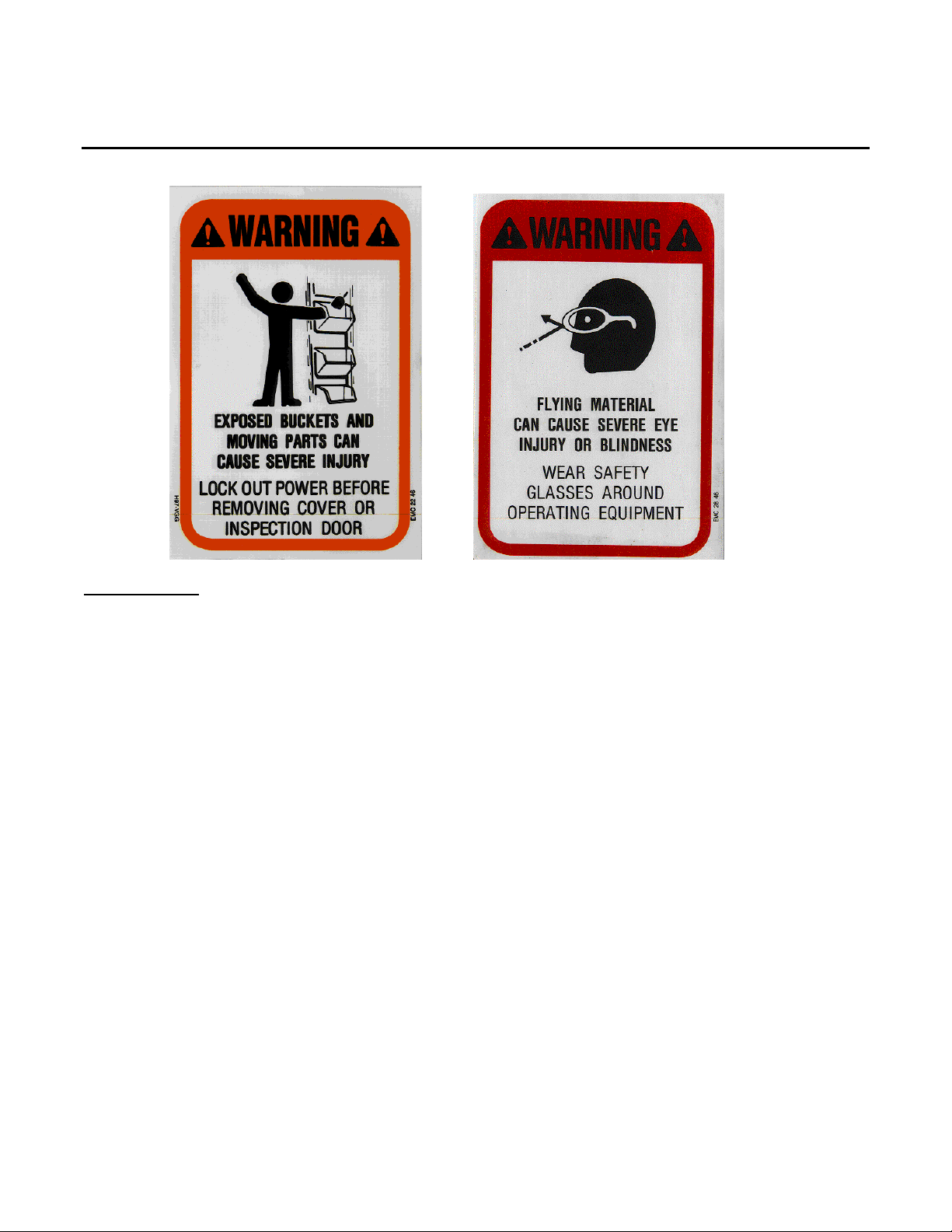
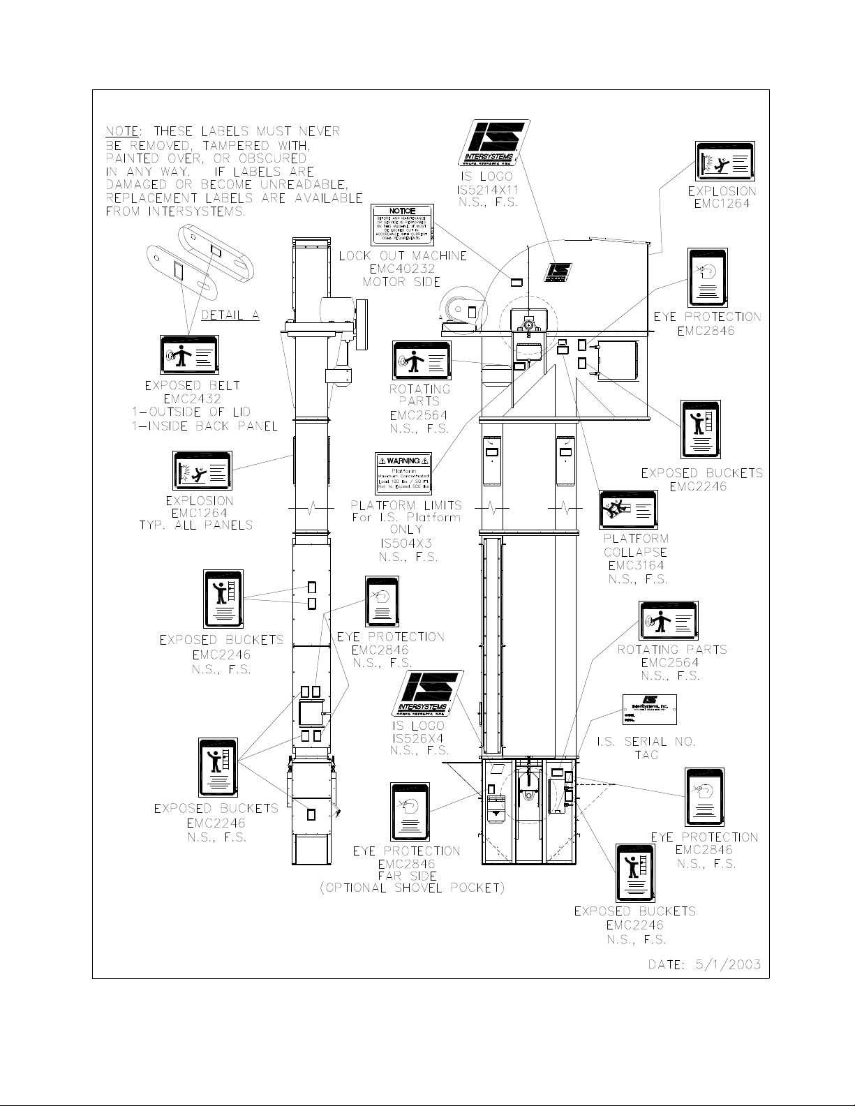
I. Safety Information....................................................................................................................................................3
II. Installation & Startup...............................................................................................................................................5
2.1 Receiving Inspection................................................................................................................................5
2.2 Pre-installation Preparation.....................................................................................................................5
2.2.1 Elevator Foundation.............................................................................................................................5
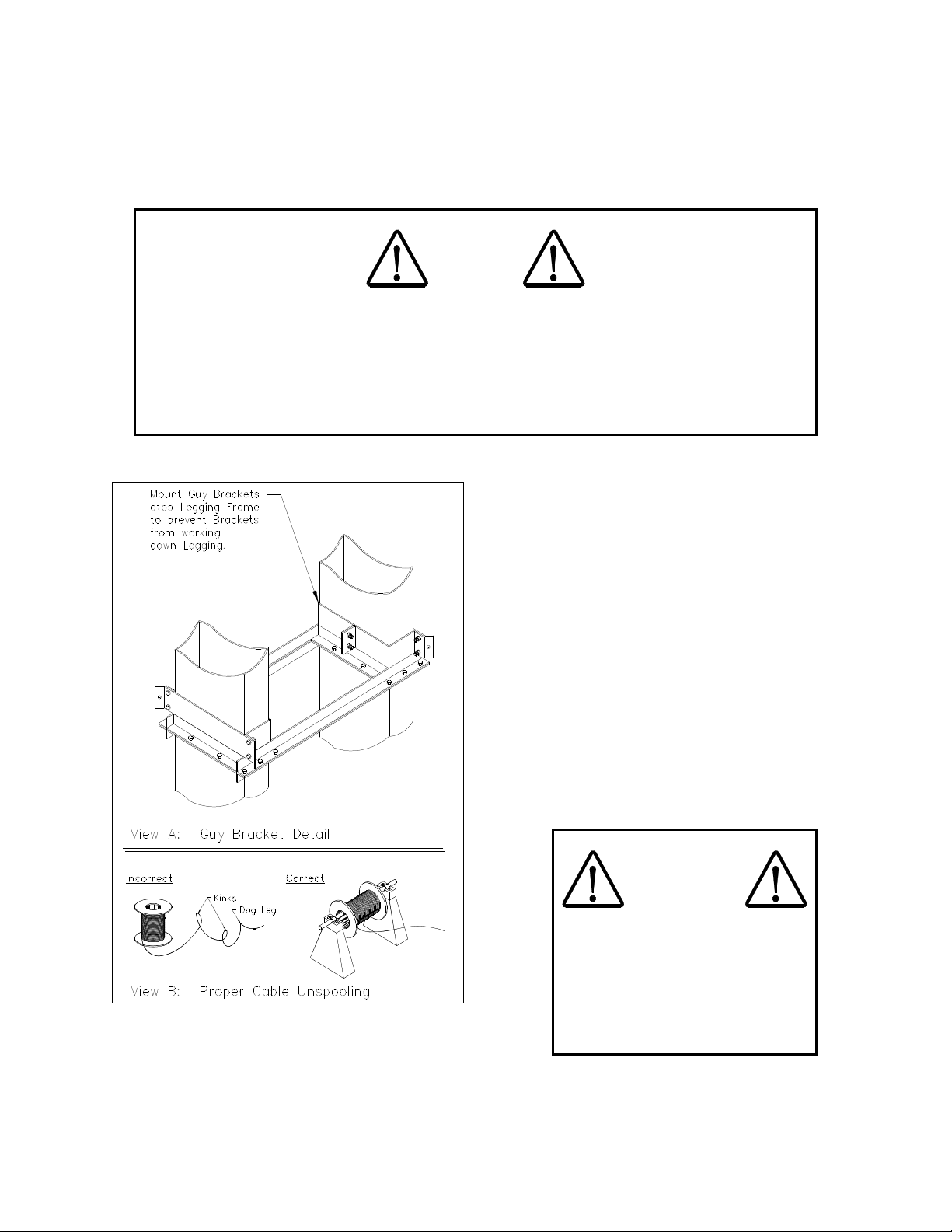
2.2.2 Elevator Guying Or Bracing .................................................................................................................6
2.2.3 Elevator Intake.....................................................................................................................................7
2.2.4 Elevator Discharge ..............................................................................................................................8
2.2.5 Positioning Trunk Sections For Ladder................................................................................................8
2.2.6 Elevator Belt Selection.........................................................................................................................8
2.3 Elevator Erection (Assembly) .................................................................................................................9
2.3.1 Vertical Assembly ................................................................................................................................9
2.3.2 Belt And Bucket Installation ...............................................................................................................17
2.3.3.1 Belt/Bucket Installation ...................................................................................................................19
2.3.3.1.1 Method 1; Simultaneous Belt And Bucket Installation;(Less than 100 Ft)...................................21
2.3.3.1.2 Method 2; Belt Only With Buckets Attached After Splicing Belt...................................................22
2.3.4 Belt Splicing .......................................................................................................................................23
2.3.5 Hood Installation .................................................................................................................................23
2.3.6 Drive Installation ................................................................................................................................23
2.3.7 Initial Belt Tracking (See Figure 2.15) ................................................................................................24
2.3.8 Rubber Throat Slide Adjustment........................................................................................................28
2.3.9 In-Service Belt Tension......................................................................................................................28
2.3.10 Elevator Bucket Filling .....................................................................................................................29
III. Maintenance ......................................................................................................................................................32
3.1 General Maintenance ...........................................................................................................................32
3.2 General Housekeepingand Periodic Inspection....................................................................................32
3.3 Lubrication ............................................................................................................................................34
3.3.1 Reducer .............................................................................................................................................34
3.3.2 Motor..................................................................................................................................................34
3.3.3 Head & Boot Shaft Bearings..............................................................................................................34
3.3.4 Roller Chain Drive..............................................................................................................................34
3.3.5 Sleeve Guides And Shafts.................................................................................................................34
3.4 Adjustment and Repair Procedure........................................................................................................34
3.4.1 Elevator Belt Tension.........................................................................................................................34
3.4.1.1 Boot Takeup (Belt Tension) Adjustment.........................................................................................34
3.4.1.2 Drive V-Belt (If Installed).................................................................................................................35
3.4.2 Belt Tracking......................................................................................................................................35
3.4.3 Belt Splicing .......................................................................................................................................35
3.4.4 Throat Slide Adjustment ....................................................................................................................35
3.4.5 Roller Chain Tension .........................................................................................................................35
IV. Spare Parts.........................................................................................................................................................36
4.1 Scope....................................................................................................................................................36
4.2 Ordering Parts ......................................................................................................................................36
V. Warranty..............................................................................................................................................................36

2

3
I. Safety Information
SAFETY FIRST! The symbols shown above identify examples of the safety labels and signs to be found on
InterSystems equipment. They are affixed to the equipment to warn of danger to persons and of possible
equipment damage. These signs must never be removed, tampered with, painted over or obscured in any way.
(see Page 4 for label locations). If labels are damaged or become unreadable, replacement labels are available
from InterSystems. User must institute a continuing program to instruct all personnel in safe operating and
maintenance procedures and to insure that all safety devices, guards, and covers are intact and operable and that
all safety signs are legible.
DO NOT exceed the elevator's rating. A certified drawing or drawings furnished with the elevator gives its capacity
in BPH (Bushels Per Hour) plus the weight per cubic foot and the weight per bushel of the commodity or material
the elevator is designed to elevate. The drawing also specifies the operating speed of the elevator belt and other
pertinent data. Consult InterSystems. before making any changes to the elevator or its operating environment; in
particular, any change in the speed or power of the elevator drive. CARELESS CHANGES COULD RESULT IN
DEATH OR SERIOUS INJURY TO PEOPLE, AND/OR REDUCE THE PERFORMANCE AND SERVICE LIFE OF
THE EQUIPMENT.
NEVER PERFORM ANY SERVICE ON THIS ELEVATOR OR ANY OTHER POWERED EQUIPMENT UNTIL
ALL POWER HAS BEEN SHUT OFF AND LOCKED OUT SO THAT IT CANNOT BE RESTORED WITHOUT
THE CONSENT AND KNOWLEDGE OF THE PERSON WHO INTERRUPTED POWER. Power includes
electrical, fluid, mechanical (cable, belt, chain, shaft, etc.), or gravity where the load or part of the equipment is
suspended. NEVER ADD RESTRAINT TO AN EXPLOSION VENT! IF THE ELEVATOR STRUCTURE IS
DAMAGED TO THE EXTENT THE RELIEF PANELS WILL NOT STAY IN POSITION, MAKE PROPER
REPAIRS! Remember the vents are designed to blow out readily, limiting damage and injury, in case of explosion.
FAILURE TO OBSERVE ALL SAFETY PRECAUTIONS, INCLUDING THOSE DICTATED BY ORDINARY
COMMON SENSE, CAN RESULT IN DEATH OR SERIOUS INJURY TO PERSONNEL, LOSS OF PRODUCT
(elevated material), AND DAMAGE OR DESTRUCTION OF THE EQUIPMENT!

4 Figure 1-2, Safety Label Location

5
II. Installation & Startup
NOTICE
Thoroughly read Section I, regarding safety information before beginning installation and startup.
2.1 Receiving Inspection
Carefully inspect the shipment for damage as soon as it is received. Verify that the quantity of parts or packages
actually received corresponds to the quantity shown on the packing slip. One or more cartons containing the
fasteners required for assembly are included with the shipment. Report any damage or shortage to the delivering
carrier as soon as possible. InterSystems' responsibility for damage to the equipment ended with acceptance by
the delivering carrier. Refer to the bill of lading. Save all paperwork and documentation furnished with any of the
elevator components.
2.2 Pre-installation Preparation
Before starting elevator installation, review this manual, the certified drawing(s) furnished with the equipment, and
other applicable documents, including but not limited to, OSHA Regulations and the National Electrical Code. You
should also obtain a copy of "Guidelines for Supporting Outside Elevator Legs", Bulletin No. F-646-75, available
from Mill Mutual Fire Prevention Bureau, North Riverside Plaza, Chicago, IL 60606, as it is referenced throughout
the manual.
InterSystems Bucket Elevators are designed to be vertically self-supporting when erected. The elevator does
require guying and/or bracing from another structure for horizontal support. The elevator has not been designed to
support other equipment such as cleaners, distributors, spouting, etc. Separate structures must be provided for
any accessory equipment.
InterSystems is the vendor of the elevator and certain of its optional accessories only, and does not assume
responsibility for the installation. The installation recommendations contained within this manual are for
consideration only. The user or installer will want to consult a civil or structural engineer regarding the design,
construction, and supervision of the entire installation, including the elevator foundation and the guying cable
and/or bracing system. The MOST IMPORTANT preparations are retaining a licensed engineer to plan the
installation and a qualified millwright or contractor to erect the elevator and the accompanying equipment and
structures.
2.2.1 Elevator Foundation
Refer to Mill Mutual Publication No F-646-75. Additionally, in the process of leveling the boot, InterSystems
recommends that the installer plan on shimming the boot around its perimeter and grouting the base plate after
the hold down fasteners are in place and tightened.

6
2.2.2 Elevator Guying or Bracing
Refer to Mill Mutual Publication No F-646-75.
DANGER
INCORRECT ATTACHMENT OF GUYING CABLES TO ELEVATOR OR BRACING FROM AN
ADJOINING STRUCTURE WILL RESULT IN SUPPORT FAILURE, COLLAPSE OF THE
ELEVATOR AND DEATH OR SEVERE INJURY TO ANYONE IN THE AREA. ATTACH GUYING
CABLES TO THE ELEVATOR ONLY BY MEANS OF THE 4-WIRE BOLT-ON BRACKETS AS
SHOWN IN FIGURE 2-1. IF BRACING FROM AN ADJOINING STRUCTURE IS USED, ATTACH
ONLY AT FLANGE JOINTS BETWEEN LEGGING SECTIONS.
NEVER attach any bracing directly to the sheet metal
trunk. Sheet metal lacks the necessary stiffness and
thickness for sound structural joints.
The engineer or contractor supervising elevator
installation is ultimately responsible for determining
suitable guying and/or bracing methods and
materials. The following considerations are
presented in addition to those set forth in Mill Mutual
Publication No F-646-75:
A. Consider placing curbs or guards around
anchors to prevent impact and damage from
area traffic.
B. Guy cables near ground level must be
guarded and made visible to prevent injuries.
C. Figure 2-1, View B shows the proper
method for unspooling cable from a reel.
DANGER
EXCESSIVE GUY CABLE TENSION
WILL TWIST, BEND AND/OR
COLLAPSE THE ELEVATOR
STRUCTURE, CAUSING SEVERE
INJURY OR DEATH. MAINTAIN
PROPER GUY CABLE TENSION
AT ALL TIMES.
Figure 2-1, Miscellaneous Guying & Bracing Details

7
2.2.3 Elevator Intake
Several factors should be taken into account when planning the intake to feed material into the elevator:
A. The method and location of intake openings in the boot usually will have been determined when the
elevator was ordered. However, if the intake arrangements have or are being changed, several factors
must be considered. See Figure 2-2
1. Inlet or Hopper Size: The size of the inlet effects the capacity and the condition of the elevated
material. Too small an inlet means the material must be fed into the boot at excessive speed. The
excess velocity of incoming material cause damage, the buckets do not fill properly, and material
backs up in the boot, clogging the inlet.
Figure 2-2, Boot Intake Conditions

8
2. UP Side Infeed Devices: The device which feeds the elevator, (auger, belt conveyor, spout, hopper,
etc.), must feed the material into the boot ABOVE the centerline of the pulley. The buckets must
complete the turn around the pulley and be moving vertically upward, not at a tangent, before
encountering material to be elevated. If the buckets ARE NOT moving vertically upward when they
encounter the incoming material, material will be forced back into the infeed device or chute.
Grinding and churning in the boot area will damage the product and excessive power will be required
to operate the system.
3. DOWN Side Infeed Devices: Several factors, most importantly the nature of the material being
elevated, are important in determining the location of down side or down leg infeed devices. If a
change in infeed arrangement from that shown on the certified drawings is contemplated, consult
InterSystems before proceeding with modifications.
4. FLOW of material to the infeed Devices: Every effort should be made when designing the feeding
equipment or spouting such that the direction of the flowing material will be perpendicular to the
buckets. Reduce or eliminate any side loading of the buckets. Achieving the bucket elevators rated
capacity is determined by even and consistant bucket fill.
2.2.4 Elevator Discharge
A. Spouting to carry off the material must be sized so that its capacity equals or exceeds the maximum
capacity of the elevator to prevent material plugging in the head or downlegging.
B. The elevator IS NOT designed to support the weight of any accessory equipment. Spouting, cleaners,
distributors, etc. must have their own supporting structures.
2.2.5 Positioning Trunk Sections for Ladder
Study the drawings to determine where each trunk section fits into the overall layout of the elevator leg. This is
important so that platforms and ladders can be attached to the elevator without having to reassemble ladder
brackets. The final ladder at the head section (at the top of the elevator) must be near the trunk closest to the
discharge (the down-leg trunk). See Figure 2-6 for ladder and cage assembly details.
2.2.6 Elevator Belt Selection
If InterSystems has supplied the belt, no further action is required at this time. However, if the belt is being
obtained independent of the elevator, those ordering the belt must be aware of a number of requirements.
A. Belt length must take into consideration the method of belt splicing to be employed in this installation.
Refer to Paragraph 2.3.4 and See Figure 2-10 for an overview of the three splicing methods commonly
employed in elevator installations. A mechanical splice requires the least extra belt while a butt splice
requires the greatest length of extra belt.
B. The pattern, spacing, and size of prepunched holes must be correct for the number, type, and size of the
buckets to be attached to the belt. If the belt is purchased with the wrong hole pattern, it will be extremely
difficult and expensive to correct the problem in the field. If the hole sizes are too small, they may have to
be redrilled in the field. If the holes are too large, the buckets may have to be redrilled to accept larger
bolts or be replaced. Elevator bolts must fit snugly in the belt.
C. The installer should fabricate spreader bars in advance to avoid delay once belt installation begins. See
Figure 2-10, View D.
D. A belt manufacturer or a local belt supplier sales representative can assist in the correct selection and
specification of belting and advise in proper installation procedures.

9
2.3 Elevator Erection (Assembly)
Erection of the elevator must not be started until the concrete foundation and the guying anchors (if any are
needed) have been completed and developed maximum strength.
NOTICE
NO MATTER WHO DOES THE INSTALLATION OR WHAT METHOD IS EMPLOYED, THE
ELEVATOR MUST BE PLUMB! IF IT IS NOT, IT ALMOST CERTAINLY CANNOT BE MADE TO
OPERATE SATISFACTORILY!
There are two basic methods of elevator erection. In this manual only the Vertical Assembly or section-by-section
method is considered. InterSystems does not recommend Horizontal Assembly wherein entire elevators or
multiple sections thereof are assembled horizontally at ground level and then raised to the vertical and hoisted into
position. The potential for damage to the elevator structure is too great.
2.3.1 Vertical Assembly
This method could also be termed section-by-section assembly. See Figure 2-3. Because of the weight of the
elevator's head section, InterSystems recommends that it always be hoisted in a separate lift and then fastened to
the rest of the elevator.
A. Lift the boot onto the foundation. (See Paragraph 2.2.1 on boot placement) BE SURE THE BOOT IS
POSITIONED CORRECTLY ON THE FOUNDATION AS SHOWN ON THE DRAWINGS.
B. While the hoisting gear is still attached to the boot to prevent its tipping, accurately plumb and level the
boot base. Use appropriate fasteners to clamp the base securely in position and grout the boot base.
Allow the grout to cure before further assembly is attempted.
C. InterSystems recommends that all joints between elevator sections be weather-proofed by applying mastic
compound, especially if the elevator is to remain an outdoor structure. Mastic or caulking compound is to
be provided by the user or installer. Do not use weather stripping. Use Grade 5 or higher bolts to connect
sections.

10
Figure 2-3, Vertical Elevator Assembly Sequence

11
DANGER
INCORRECT PLACEMENT OF TRUNK SECTIONS OF VARYING GAGE SHEET METAL
COULD RESULT IN SUPPORT FAILURE, COLLAPSE OF THE ELEVATOR AND DEATH OR
SEVERE INJURY TO ANYONE IN THE AREA. TRUNK SECTIONS OF VARYING GAGE MUST
BE INSTALLED IN THE LOCATIONS SHOWN ON THE CERTIFIED DRAWINGS WITH THE
HEAVIER GAGES TOWARD THE BOTTOM.
D. Begin lifting succeeding elevator sections into position. In most but not all installations, the inspection
elevator section is the next section after the boot to be installed.
1. Certain applications, particularly tall elevators, impose heavy structural loads on the elevator leg and
boot sections. In these applications, lower trunk sections and the boot section are fabricated from
heavier gage materials. Packing list indicates quantity of each gage of trunk. Individual pieces are
labeled to show gage.
2. Continually refer to the certified drawings so that trunk sections are correctly positioned for ladder
attachment.
3. If the customer has ordered the elevator with optional explosion vents in certain elevator sections,
these sections must be located in their specified locations.
4. If the elevator includes a short (non-standard) height elevator section, the certified drawings furnished
with the elevator will indicate its intended position, usually immediately above the inspection section.
E. Plumb each elevator section as it is positioned on the preceding section. Attach guying and/or bracing as
determined by pre-installation planning. Shim as required to plumb each section and tighten assembly
fasteners. See Figure 2-4. The elevator shipment included one or more containers of bulk fasteners,
sufficient to completely assemble the elevator and any accessories ordered with it. FASTENERS WERE
NOT PROVIDED FOR ASSEMBLY OR ATTACHMENT OF BRACES OR ANY OTHER EQUIPMENT.

12
F. The last elevator section to be lifted into position onto the
elevator is ALWAYS the head section. (The hood is not
assembled until belt and cup installation is complete). Lift the
head onto the top elevator section. See Figure 2-5. DO NOT
install the hood at this time. Plumb the head section and
fasten it to the elevator trunk.
G. The basic elevator structure should now be complete,
securely braced and/or guyed.
H. Assemble the service platform on the elevator head. If
supplied by InterSystems, a drawing will be furnished, giving
specific assembly instructions and a list of specific fasteners
for each detail. Do not weld any platform clamping brackets
until all platforms and ladders are assembled and correct
installation has been verified.
I. Assemble the other service and rest platforms if any were
ordered and supplied.
J. Follow these guidelines while assembling ladders:
1. A length of ladder will lead up to a platform and extend
upward through the platform opening to the level of the
platform's top rail.
2. An elevator may include a short section of trunk. In
these cases, an extra ten foot section of ladder and
safety cage is furnished. This ladder and cage section is
to be field-modified to match the short section of trunk
exactly and compensate for any variances.
3. The total lengths of safety cage will not equal the total
lengths of ladders when rest platforms are used. The
bottom edges of the hoops are spaced approximately 7
ft above the floor level of the platforms.
4. The bottom of the ladder, whether at ground or grade level or at the working floor, should be
surrounded by a lockable safety cage or otherwise arranged to prohibit access to unauthorized
personnel.
K. IMPORTANT: When the installer is confident that ALL ladders and platforms are correctly assembled and
located, weld all platform support channels to the elevator casing (trunk). The clamp bands used to
temporarily position the support channels during installation were NOT meant to permanently attach the
channels to the trunk.
Figure 2-4, Elevator Joint Fasteners
Figure 2-5, Lifting Hole Locations

13
Figure 2.6, Typical Ladder and Cage Assembly

14
Figure 2.7a, Typical Small Head Service Platform Assembly

15
Figure 2.7b, Typical Large Head Service Platform Assembly

16
Figure 2.8, Typical Head Service Hatch Assembly

17
2.3.2 Belt and Bucket Installation
There are two basic methods of installing the belt and buckets in an elevator. Any of three styles of belt splice can
be selected. Customers usually have a definite preference as to the style of splice used. Various methods of
belt/bucket installation and belt splicing are covered in the following paragraphs. See Figures 2-9 and 2-10.
Figure 2-9, Belt & Bucket Installation

18
Figure 2-10, Belt Splicing Methods

19
2.3.3.1 Belt/Bucket Installation
The choice of methods used to install the belt and buckets is determined by: 1) length and weight of belt, 2)
number, size, and weight of buckets, 3) open area available around the base of the elevator, and 4) available
equipment.
REMINDER: THE HOOD IS NOT YET ASSEMBLED TO THE HEAD SECTION.
The drawings furnished with the elevator identify the belt to be used, either as furnished by InterSystems or as
specified by the customer, if provided by others. The drawings also specify the type, size, number, spacing, and
pattern of buckets on the belt.
A. If the elevator boot includes a manual screw takeup as shown in Figure 2-11, adjust the takeup screws to
raise the pulley to its highest level
OR
B. If the elevator includes a Posi-Guide gravity takeup as shown in Figure 2-12, position a jack under the
indicated surface of the takeup side post to lift the takeup, including the pulley.
WARNING
AN IMPROPERLY SUPPORTED POSI-GUIDE GRAVITY TAKEUP CAN SLIP OUT OF
POSITION OR FALL, CAUSING SERIOUS INJURY OR DAMAGE. ASSURE PROPER
PLACEMENT OF JACK AND SUPPORTS.
C. Rig a heavy haulage line (rope or cable) through the removable panel in the UP leg through which the belt
with buckets attached will be pulled into the elevator. The line is then hauled up the UP leg, over the head
pulley, and down the DOWN elevator leg. Usually, the line can be passed around the boot takeup pulley
and out of a cleanout panel to a winch so the belt can be pulled into the elevator. A spreader bar should
be fabricated to connect the haulage line to the belt. See Figure 2-10, View D. The bar is preferred to
simply punching a hole in the belt and tying or clamping the line to the belt.
D. "Acme" Nuts should both be tightened against Support Plate to prevent vibration from moving the Takeup
out of alignment. Should the Takeup Screw ever require replacement make certain to loosen both "Acme"
Nuts to relieve any upward or downward tension before removing the retainer bolts.
E. The Connection Bolts must be loosened while aligning pulley with adjusting screws and retightened when
alignment is complete. Do not add weight to the weight box unless otherwise instructed by the factory.
The weight of the takeup, boot bearings, etc., provides proper belt tension in most applications. Additional
weight may cause damage to the belt.
Table of contents
Other GSi Elevator manuals