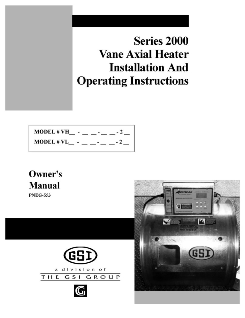
GSi 10 HP Guide

PNEG-297
Chi-Town Heater
Installation & Operation
PNEG-297
Date: 02-18-10

2 PNEG-297 Chi-Town Heater
Check List
1. All wire connections
2. Ignitor gap - .125
3. Pipetrain tightness and gas leaks
4. Flame probe adjusted
5. Fuse in place, extra fuse provided
6. Reset lockout after 30 second flame out.
7. Indicator light
8. Pressure gauge
9. Regulator adjusted
10. Solenoid valve operates correctly
11. Unit cycles ON to OFF
12. Burns evenly around ring
13. All decals and serial number tag
14. Aesthetic appearance
15. Manual
Tester Signature______________________________
Date______________________________
Model #:______________________________

PNEG-297 Chi-Town Heater 3
Table of Contents
Contents
Chapter 1 Introduction ....................................................................................................................... 4
Chapter 2 Safety .................................................................................................................................. 5
General Safety Statements ................................................................................................. 5
Safety Alert Symbol ............................................................................................................. 6
Roof Damage Warning and Disclaimer ............................................................................... 6
Chapter 3 Safety Decals ..................................................................................................................... 7
Chapter 4 Specifications .................................................................................................................... 9
Heater Specifications ..........................................................................................................9
Chapter 5 Installation ....................................................................................................................... 10
Heater Installation ............................................................................................................. 10
Fuel Connection ................................................................................................................11
Electrical Connection ........................................................................................................ 11
Standard Heater - Second Heater Installation .................................................................. 13
Chapter 6 Installation & Operating .................................................................................................. 14
Bin Configuration ............................................................................................................... 14
Chapter 7 Operating Instructions .................................................................................................... 15
Heater Operation ...............................................................................................................15
Chapter 8 Heater Service ................................................................................................................. 18
Chapter 9 Wiring ............................................................................................................................... 19
Chapter 10 Schematic ...................................................................................................................... 21
Chapter 11 Time Delay Operation ................................................................................................... 22
HH-1089E Time Delay Reset Operation ......................................................................... 22
Chapter 12 Troubleshooting Guide ................................................................................................. 23
Chapter 13 Parts List ........................................................................................................................ 25
Gas Heater Parts ............................................................................................................. 26
Control Box Parts ............................................................................................................ 28
Pipe Train Parts ...............................................................................................................30
Chapter 14 Warranty ......................................................................................................................... 33

4 PNEG-297 Chi-Town Heater
1. INTRODUCTION
Thank you for choosing a GSI product. It is designed to give excellent performance and service
for many years.
This manual describes the operation of the Chi-Town Heater. It is designed for low to medium
temperature grain conditioning, and is ideal for the aeration of rice, popcorn or other select
grains. It is designed to be used with propane vapor or natural gas.
The principal concern of the The GSI Group Inc. ("GSI") is your safety and the safety of others
associated with grain handling equipment. This manual is written to help you understand safe
operating procedures, and some of the problems that may be encountered by the operator or
other personnel.
As owner and/or operator, it is your responsibility to know what requirements, hazards and
precautions exist, and to inform all personnel associated with the equipment, or who are in the
dryer area. Avoid any alterations to the equipment. Such alterations may produce a very
dangerous situation, where serious injury or death may occur.

PNEG-297 Chi-Town Heater 5
2.SAFETY
General Safety Statements
The GSI Group Inc’s Principal concern is your safety and the safety of others associated with
grain handling equipment. We want to keep you as a customer. This manual is to help you
understand safe operating procedures and some problems which may be encountered by the
operator and other personnel.
As owner and/or operator, it is your responsibility to know what requirements, hazards and
precautions exist and inform all personnel associated with, or in the area of the product. Safety
precautions may be required from the personnel. This product is ideal for the conditioning of
corn, soy beans or other select grains. Avoid any alteration to the equipment, such alterations
may produce a very dangerous situation, where serious injury or death may occur.
This is the safety alert symbol. It is used to alert you
to potential personal injury hazards. Obey all safety
messages that follow this symbol to avoid possible
injury or death.
DANGER indicates an imminently hazardous situation
which, if not avoided, will result in death or serious injury.
WARNING indicates a potentially hazardous
situation which, if not avoided, could result in death or
serious injury.
CAUTION indicates a potentially hazardous situation
which, if not avoided, may result in minor or moderate
injury.
CAUTION used without the safety alert symbol indicates
a potentially hazardous situation which, if not avoided,
may result in property damage.
NOTE indicates information about the equipment that
you should pay special attention to.

6 PNEG-297 Chi-Town Heater
2. SAFETY
Safety Alert Symbol
Roof Damage Warning and Disclaimer
BE ALERT! DANGER!
Personnel operating or working around electrical equipment should
read this manual. This manual must be delivered with equipment to
its owner. Failure to read this manual and its safety instructions is a
misuse of the equipment.
GSI DOES NOT WARRANT ANY ROOF DAMAGE
CAUSED BY EXCESSIVE VACUUM OR INTERNAL
PRESSURE FROM FANS OR OTHER AIR MOVING
SYSTEMS. ADEQUATE VENTILATION AND/OR
"MAKEUP AIR" DEVICES SHOULD BE PROVIDED
FOR ALL POWERED AIR HANDLING SYSTEMS.
GSI DOES NOT RECOMMEND THE USE OF
DOWNWARD FLOW SYSTEMS (SUCTION).
SEVERE ROOF DAMAGE CAN RESULT FROM
ANY BLOCKAGE OF AIR PASSAGES. RUNNING
FANS DURING HIGH HUMIDITY/COLD WEATHER
CONDITIONS CAN CAUSE AIR EXHAUST OR
INTAKE PORTS TO FREEZE.

PNEG-297 Chi-Town Heater 7
3.SAFETYDECALS
The GSI Group Inc. recommends that you contact your local power company and have a
representative review your installation so your wiring will be compatible with their system and so
that you will have adequate power supplied to your unit.
If a decal is damaged or missing contact:
The GSI Group Inc.
1004 E. Illinois St.
Assumption, IL 62510
Ph: 1-217-226-4421
A free replacement will be sent to you.
OFF ON HIGH FLAME
VAPOR HI-LIMIT
THERMOSTAT RESET
READ OWNERS MANUAL BEFORE OPERATING
DC-1878
HEATER CANNOT START IF RESET LIGHT IS
BLINKING. TO RESET TURN SWITCH OFF FOR
10 SECONDS THEN BACK ON.

8 PNEG-297 Chi-Town Heater
3. SAFETY DECALS
CAUTION
Thermostat must be installed for operation.
DC-1702
Failure to do so may damage equipment
and cause fire.
IMPORTANT
THIS UNIT IS WIRED FOR
115 VOLT, 1-PHASE
POWER SUPPLY
420-1422-5

PNEG-297 Chi-Town Heater 9
4.SPECIFICATIONS
Heater Specifications
Common Measurements
All Models
Inside Diameter 25-7/8"
Bolt Circle Diameter 27-3/16"
Length 18"
Weight 110 lbs
Propane Vapor
Orifice (inches) 5/32
Maximum Fuel Flow (CFH) 475
Min. Operating Pressure (psi) 1
Max. Operating Pressure (psi) 15
Min. Supply Line (inches) 1/2
BTU Rating @ Max. Pressure 1,100,000
Natural Gas
Orifice (inches) 7/32
Maximum Fuel Flow (CFH) 1083
Min. Operating Pressure (psi) 1
Max. Operating Pressure (psi) 8
Min. Supply Line (inches) 3/4
BTU Rating @ Max. Pressure 1,100,000

10 PNEG-297 Chi-Town Heater
5. INSTALLATION
Heater Installation
1. Install three(3) mounting brackets on fan as indicated by the arrows shown in Figure 5A.
Install loosely.
2. Set heater in place and install fourth (4) mounting bracket.
3. Level heater and tighten mounting brackets.
4. Attach heater to mounting brackets using 1/4" bolts and nuts.
Figure 5A Heater Mounting Brackets Illustration

PNEG-297 Chi-Town Heater 11
5. INSTALLATION
Fuel Connection
Important: Do not use propane tanks which have previously been used for ammonia unless they
have been purged according to procedures of the National L.P. Association.
Investigate to be sure that the fuel supply system complies with all local codes for L.P.
gas installations.
Propane Vapor Models
1. Propane vapor models are designed to run directly off of supply tank or from a separate
external vaporizer.
2. Run proper size line (see specification on Page 9) to pipetrain on heater. Have a qualified
gas service person inspect installation to be sure everything is installed according to local
codes and ordinances.
3. After installation is complete check all connections for leaks.
Natural Gas Models
1. Natural gas models are similar to vapor models, but have a larger orifice to accommodate
lower pressure, sometimes found with natural gas.
2. Run proper size line (see specifications on Page 9) to pipetrain on heater. Have a qualified
gas service person inspect installation to be sure everything is installed according to local
codes and ordinances.
3. After installation is complete check all connections for leaks.
Electrical Connection
Standard electrical safety practices and codes should be used when working with a heater.
Refer to the National Electric Code Standard Handbook by the National Fire Protection
Association. A qualified electrician should make all wiring installations.
1. Connect power cord to fan control box.
2. Make field connections in fan box as shown in Figure 5B.
Important: Heater must be interlocked with fan for safe operation.
3. Connect deluxe thermostat control (optional) as shown in Figure 5B.
Important: Thermostat must be installed for safe operation.
ALWAYS DISCONNECT AND LOCK OUT POWER BEFORE WORKING ON
OR AROUND HEATER

12 PNEG-297 Chi-Town Heater
5. INSTALLATION
IMPORTANT: Heater must be interlocked with fan for safe operation.
Heater Power Connection
1. Connect power cord to fan control box.
2. Make field connections in fan box as shown in Figure 5B.
3. Connect deluxe thermostat control as shown in Figure 5B.
IMPORTANT: Thermostat must be installed for safe operation.
Figure 5B Heater Wiring Installation on a Fan Unit

PNEG-297 Chi-Town Heater 13
5. INSTALLATION
Standard Heater - Second Heater Installation
Two (2) standard heaters may be connected to one grain drying system and wired so they cycle
together. One of the heaters should have a thermostat connected to it as per the installation
instructions. That heater will be referred to as the primary. The other heater (without the
thermostat) will be referred to as the secondary.
1. Install relay base (TD-100283) in primary heater control box.
2. Connect wire between terminal 13 on relay base to terminal 6 on terminal strip in
primary heater.
3. Connect wire between terminal 14 on relay base to terminal 3 on terminal strip in
primary heater.
4. Run two (2) wires (18 gauge) between primary and secondary heater.
5. Connect wires to terminals 5 and 9 (points A and B) on relay base in primary heater.
6. Connect wire from terminal 9 in primary to terminal 5 (point F) in secondary unit.
7. Connect wire from terminal 5 in primary to terminal 8 (point G) in secondary unit.
8. Install relay (TD-100282) in relay base.
Follow these additional steps for HIGH-LOW units.
1. Install relay base (TD-100283) in master heater control box.
2. Connect wire between terminal 13 (point E) on relay base to green wire from HIGH-LOW
thermostat in master unit. Do not disconnect other wires from green wire 3. Connect wire
between terminal 14 on relay base to terminal 14 on other relay base in master heater.
3. Run two (2) wires (18 gauge) between master and slave heater.
4. Connect wires to terminals 5 and 9 (points C and D) on relay base in master heater.
5. Connect wire from terminal 9 in master to terminal 6 (point H) in slave unit.
6. Connect wire from terminal 5 in master to cycle solenoid and red light in slave unit. Do not
connect wire to side of cycle solenoid and light that are connected to terminal.
Figure 5C Standard Heater - Second Heater Relay Connection

14 PNEG-297 Chi-Town Heater
6. INSTALLATION & OPERATING
Bin Configuration
Figure 6A
Important: When mounting (2) heaters on a bin it is imperative that they be situated as in above
drawing. Plenum thermostat must be to the right of primary heater and primary heater
must be to the right of secondary heater.
Plenum Temperatures
Important: DO NOT EXCEED PLENUM TEMPERATURES LISTED IN TABLE
Operating Temperature Table
Note: THIS TABLE IS NOT INTENDED AS A DRYING GUIDE. IT SHOULD BE USED AS A
REFERENCE FOR SETTING MAXIMUM PLENUM TEMPERATURE FOR SAFE
OPERATION.
LO-TEMP
BATCH
HIGHTEMP BATCH
DRY NO STIRRING
HIGHTEMP WITH
STIRRING
CONTINUOUS FLOW
(RECIRCULATING)
CORN 5-20° ABOVE
AMBIENT TEMP
120° 140° 160°
RICE 5-10° ABOVE
AMBIENT TEMP
100° 100° NOT
RECOMMENDED
BEANS &
WHEAT
5-20° ABOVE
AMBIENT TEMP
110° 120° NOT
RECOMMENDED

PNEG-297 Chi-Town Heater 15
7.OPERATINGINSTRUCTIONS
Heater Operation
1. Thermostat must be wired into heater control box for heater to operate.
2. Open all manual shut-off valves to heater unit.
3. Start fan. This will supply power to heater.
4. Turn thermostat dial to its highest setting.
5. Turn heater toggle switch to ON.
6. Heater should now be lit. If not, check to see that all gas is on and thermostat is wired in.
7. Watch thermometer on plenum and when it reaches desired temperature turn thermostat
back slowly until heater cycles OFF.
8. Gas pressure should be adjusted so burner is on 75% of the time. (see charts on Page 14)
9. Watch plenum temperature as burner goes through a few cycles to be sure it is operating
properly.
Figure 7A Propane Vapor Pipetrain

16 PNEG-297 Chi-Town Heater
7. OPERATING INSTRUCTIONS
BTU's per Gauge Pressure (psi) - Propane Models Approximate
Gauge Pressure (psi) Required to Maintain Temperatures (Approximate)
Operating Pressure (psi)
12345678910
294,339 416,382 509,709 588,678 658,075 720,293 777,725 832,764 880,624 930,877
12 14 15
1,019,418 1,100,780 1,136,675
Fan Model Static Pressure
Heat Rise Degrees F
20 30 40 50 60 70 80
10 HP
2 124581014
3 12357912
4 12346812
5 1234579
15 HP
2 236812- -
3 23581214-
4 1347914-
5 124681014
20 HP
324712---
42471015--
52461014--
6 236912- -
25 HP
3 3612----
4 3610----
535914---
625814---
30 HP
4 3712----
6 3610----
835914---
10 246914- -
40 HP
4 512-----
6 49-----
8 4814----
10 3 6 10 15 - - -

PNEG-297 Chi-Town Heater 17
7. OPERATING INSTRUCTIONS
BTU's per Gauge Pressure (psi) - Natural Gas Models Approximate
Gauge Pressure (psi) Required to Maintain Temperatures (Approximate)
Operating Pressure (psi)
12345678
397,280 562,640 688,480 793,520 888,160 973,440 1,051,440 1,126,320
Fan Model Static Pressure
Heat Rise Degrees F
20 30 40 50 60 70 80
10 HP
2 112346 7
3 112345 7
4 112345 6
5 112234 5
15 HP
2 12357 - -
3 123458 -
4 123457 -
5 122356 8
20 HP
3 1346 - - -
4 12468 - -
5 12468 - -
6 12357 - -
25 HP
3 246----
4 236----
5 2358 - - -
6 2357 - - -
30 HP
4 247----
6 246----
8 2357 - - -
10 12457 - -
40 HP
4 36-----
6 35-----
8 248----
10 2358 - - -

18 PNEG-297 Chi-Town Heater
8. HEATER SERVICE
All heaters are constructed of durable weather-resistant materials, so a minimum amount of
service should be required. Before the unit is started for the first time each season there are a
few items that need to be checked out. All damaged parts should be repaired or replaced.
1. Disconnect and lockout power to fan and heater. Open control box lid and inspect all
components for moisture, vibration or rodent damage. Inspect and tighten all loose terminal
connections. Replace any damaged wiring.
2. Remove burner orifice tube and inspect for dirt or foreign material. Clean out if necessary.
3. Inspect holes in burner ring for possible corrosion or plugging with dirt or rust. Clean if
necessary.
4. Be sure primary air inlet screen is intact and clean for proper burn.
5. Check perforated ring on natural gas models to be sure it is clean and no holes are plugged.
6. Inspect flame probe and ignitor and adjust or replace if necessary.
ALWAYS DISCONNECT AND LOCK OUT POWER BEFORE WORKING ON
OR AROUND HEATER

PNEG-297 Chi-Town Heater 19
9.WIRING
Figure 9A
NOTE: Move transformer wire from terminal 5 to 8 for continuous spark.

20 PNEG-297 Chi-Town Heater
9. WIRING
Figure 9B
Note: Move transformer wire from terminal 5 to 8 for continuous spark.
This manual suits for next models
5
Table of contents
Other GSi Heater manuals
Popular Heater manuals by other brands

Webasto
Webasto Thermo Call TC2 COMFORT operating manual

MILL
MILL IB250 Assembly and instruction manual

Jaga
Jaga MINI FREESTANDING HYBRID Installation and operation manual

Frico
Frico Infragold IHG10W Assembly and operating instructions

Unold
Unold 86585 Instructions for use

Omega
Omega Altise OC1005 instruction manual