GSi PNEG-012 Series Owner's manual

PNEG-012
Vane Axial Heater
Installation and Operation
Model #:
Owner’s Manual
PNEG-012
Date: 10-30-09

2PNEG-012 Vane Axial Heater
Heater Check List
1. All wire connections
2. Spark plug gap 0.125
3. Pipe train tightness and gas leaks
4. Flame sensor tight
5. Fuse in place, extra fuse provided
6. Time delay reset
7. Indicator light
8. Pressure gauge
9. Regulator adjusted
10. Shut off valve operates correctly
11. Vapor high-limit
12. Unit cycles ON to OFF
13. Heat rise even across transition
14. Unit cycles high to low (high-low only)
15. Modulating valve holds temperature within 1° (mod units only).
16. All decals and serial number tag
17. Aesthetic appearance
18. Manual
Tester Signature:___________________________
Date: ____________________________________

Table of Contents
PNEG-012 Vane Axial Heater 3
Contents
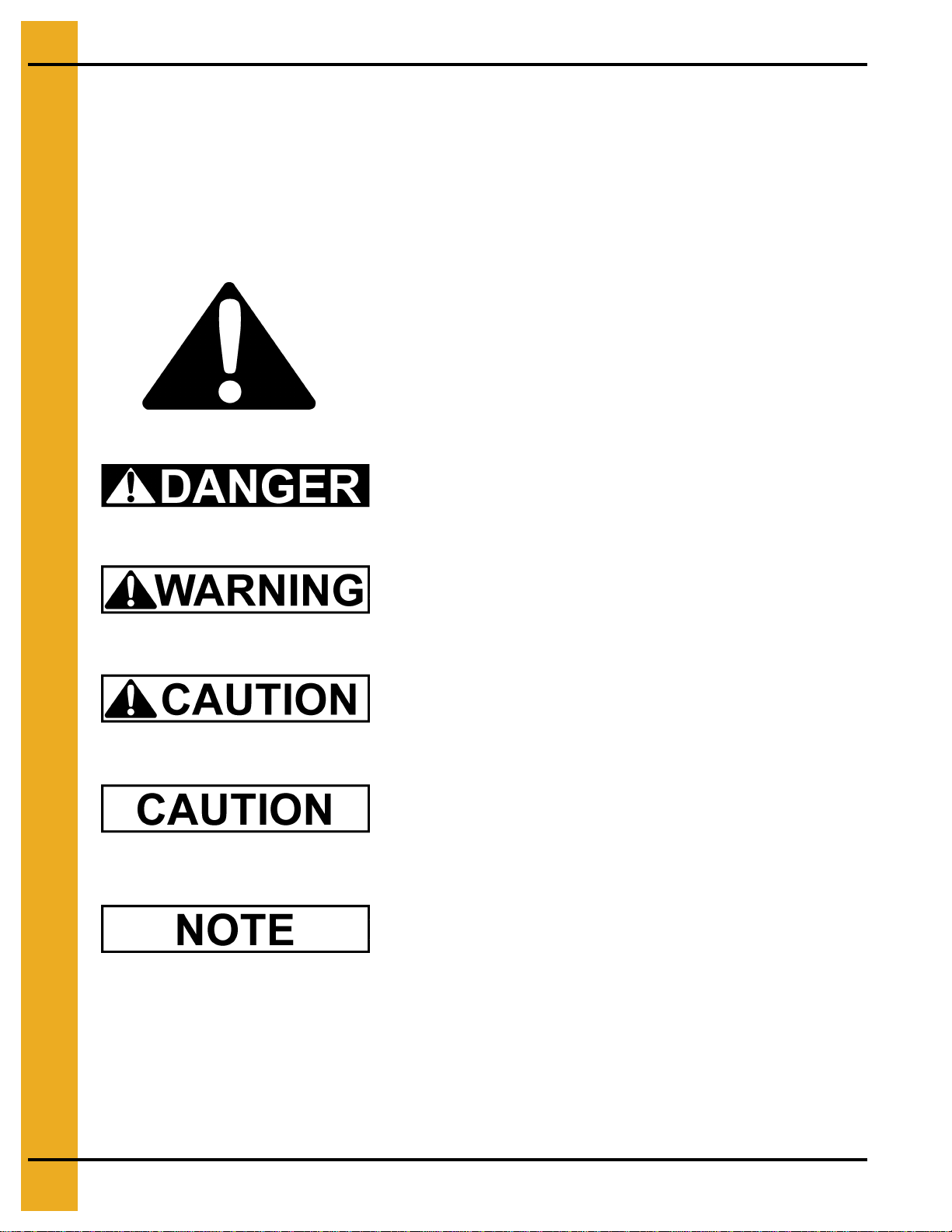
Chapter 1 Safety .................................................................................................................................................. 4
Safety Guidelines ............................................................................................................................... 4
Introduction ........................................................................................................................................ 5
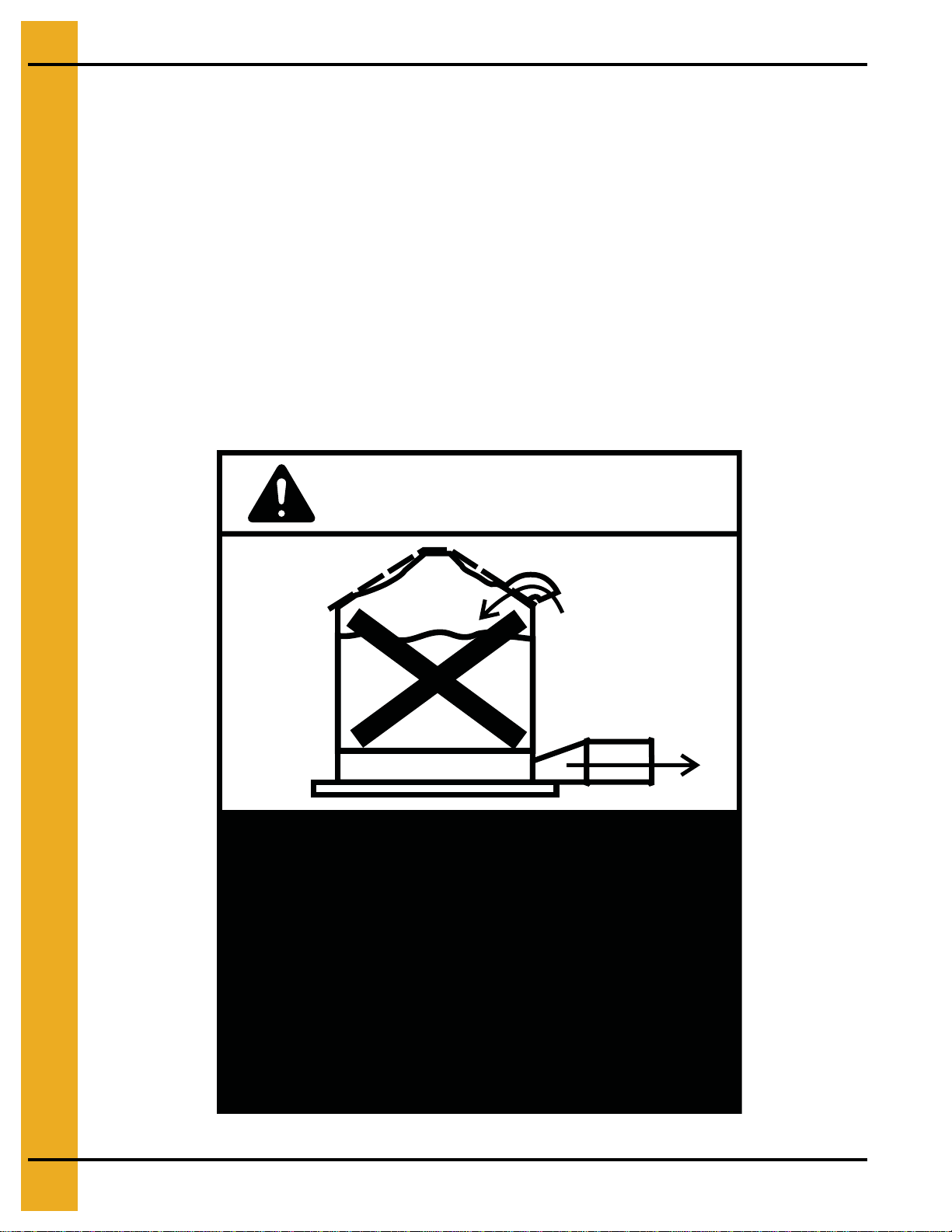
Chapter 2 Safety Decals ..................................................................................................................................... 6
Roof Damage Warning and Disclaimer .............................................................................................. 6
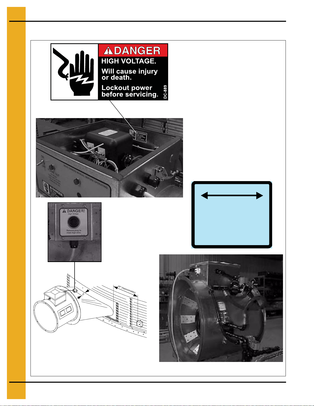
Heater Access Door Decals ............................................................................................................... 7
Control Box Decals ............................................................................................................................ 8
Chapter 3 Specifications .................................................................................................................................... 9
Heater Specifications ......................................................................................................................... 9
Chapter 4 Installation ....................................................................................................................................... 10
Fuel Connection ............................................................................................................................... 10
Liquid Propane Models .................................................................................................................... 10
Propane Vapor Models .................................................................................................................... 10
Natural Gas Models ......................................................................................................................... 10
Standard Heater Electrical Installation ............................................................................................. 10
Standard Heater - Second Heater Installation ................................................................................. 12
Deluxe Heater Electrical Installation ................................................................................................ 13
Deluxe Heater - Second Heater Installation ..................................................................................... 14
Bin Configuration .............................................................................................................................. 15
Transition High-Limit Installation ...................................................................................................... 15
Plenum Thermostat Mounting .......................................................................................................... 16
Heater Setup .................................................................................................................................... 17
Chapter 5 Operation ......................................................................................................................................... 18
Operating Temperature Table .......................................................................................................... 18
Cycling Heater Operation ................................................................................................................. 18
Time Delay Operation - Standard Heater.......................................................................................... 19
High-Low Heater Operation ............................................................................................................. 20
Modulating Valve Operation ............................................................................................................. 21
Adjusting the Vaporizer .................................................................................................................... 22
BTUs per Gauge Pressure (PSI) - Propane Models (Approximate) ................................................. 23
BTUs per Gauge Pressure (PSI) - Natural Gas Models (Approximate) ........................................... 24
Chapter 6 Service .............................................................................................................................................. 25
Chapter 7 Troubleshooting - Standard Heater................................................................................................ 26
Chapter 8 Wiring Diagrams .............................................................................................................................. 27
Standard Heater Wiring .................................................................................................................... 27
Standard Heater Schematic ............................................................................................................. 28
Deluxe Heater .................................................................................................................................. 29
Chapter 9 Parts List .......................................................................................................................................... 30
Standard Heater Control Box Parts .................................................................................................. 30
Deluxe Heater Control Box Parts ..................................................................................................... 32
18" Gas Heater Parts ....................................................................................................................... 33
24", 26" and 28" Gas Heater Parts ................................................................................................... 34
18" Vapor/NG Pipe Train Assembly ................................................................................................. 36
24", 26" and 28" LP Pipe Train Assembly ........................................................................................ 37
24", 26" and 28" LP High-Low Pipe Train Assembly ........................................................................ 38
24", 26" and 28" LP Modulating Pipe Train Assembly ..................................................................... 39
24", 26" and 28" Vapor/NG Pipe Train Assembly ............................................................................ 40
24", 26" and 28" Vapor/NG High-Low Pipe Train Assembly ............................................................ 41
24", 26" and 28" Vapor/NG Modulating Pipe Train Assembly .......................................................... 42
LP Supply Pipe Train Assembly ....................................................................................................... 43
Chapter 10 Warranty ......................................................................................................................................... 45

4PNEG-012 Vane Axial Heater
1. Safety
Safety Guidelines
This manual contains information that is important for you, the owner/operator, to know and understand.
This information relates to protecting personal safety and preventing equipment problems. It is the
responsibility of the owner/operator to inform anyone operating or working in the area of this equipment
of these safety guidelines. To help you recognize this information, we use the symbols that are defined
below. Please read the manual and pay attention to these sections. Failure to read this manual and its
safety instructions is a misuse of the equipment and may lead to serious injury or death.
This is the safety alert symbol. It is used to alert you to
potential personal injury hazards. Obey all safety
messages that follow this symbol to avoid possible
injury or death.
DANGER indicates an imminently hazardous situation
which, if not avoided, will result in death or serious injury.
WARNING indicates a potentially hazardous situation
which, if not avoided, could result in death or serious injury.
CAUTION indicates a potentially hazardous situation
which, if not avoided, may result in minor or moderate injury.
CAUTION used without the safety alert symbol indicates a
potentially hazardous situation which, if not avoided, may
result in property damage.
NOTE indicates information about the equipment that you
should pay special attention.

1. Safety
PNEG-012 Vane Axial Heater 5
Introduction
Thank you for choosing a GSI product. It is designed to give excellent performance and service for
many years.
This manual describes the operation of the Deluxe and Standard Vane Axial Heater: VHD and VHS. It
is designed for low to medium temperature grain conditioning, and is ideal for the aeration of rice,
popcorn or other select grains. It is available in both propane vapor and natural gas models.
Our foremost concern is your safety and the safety of others associated with this equipment. We want
to keep you as a customer. This manual is to help you understand safe operating procedures and some
problems which may be encountered by the operator and other personnel.
As owner and/or operator, it is your responsibility to know what requirements, hazards and precautions
exist, and to inform all personnel associated with the equipment or in the area. Safety precautions may
be required from the personnel. Avoid any alterations to the equipment. Such alterations may produce
a very dangerous situation where SERIOUS INJURY or DEATH may occur.
This equipment shall be installed in accordance with the current installation codes and applicable
regulations which should be carefully followed in all cases. Authorities having jurisdiction should be
consulted before installations are made.

6PNEG-012 Vane Axial Heater
2. Safety Decals
If a decal is damaged or missing contact:
GSI Decals
1004 E. Illinois St.
Assumption, IL. 62510
Phone: 1-217-226-4421
A free replacement will be sent to you.
Roof Damage Warning and Disclaimer
The manufacturer does not warrant any roof damage caused by excessive vacuum or internal
pressure from fans or other air moving systems. Adequate ventilation and/or “makeup air”
devices should be provided for all powered air handling systems. The manufacturer does not
recommend the use of downward flow systems (suction). Severe roof damage can result from
any blockage of air passages. Running fans during high humidity/cold weather conditions can
cause air exhaust or intake ports to freeze.
CAUTION!
Excessive vacuum (or pressure) may
damage roof. Use positive aeration
system. Make sure all roof vents are
open and unobstructed. Start roof
fans when supply fans are started.
Do not operate when conditions exist
that may cause roof vent icing.
DC-969

2. Safety Decals
PNEG-012 Vane Axial Heater 7
Heater Access Door Decals
Stay clear of rotating
blade. Blade could start
automatically. Can cause
serious injury. Disconnect
power before servicing.
DC-1225
WARNING
DC-1227
Flame and pressure beyond
door can cause serious
injury. Do not operate with
service door removed. Keep
head and hands clear.
WARNING
Size: 4.875" x 2.25"
Located above access door on
heater housing.
See Note below.
DC-1225
DC-1227
Size: 4.875" x 2.25"
Located above access door on
heater housing.
See Note below.
DC-113
Size: 4.75" x 1.625"
Located above access door on
heater housing.
NOTE: May be substituted with DC-1559 combination decals.

2. Safety Decals
8PNEG-012 Vane Axial Heater
Control Box Decals
WARMER COLDER
VAPORIZER ADJUSTMENT
VAPORIZER COIL SHOULD BE ADJUSTED
SO VAPOR PIPE TRAIN IS WARM
(100°F-125°F) TO THE TOUCH
DC-535
Size: 2.813" x 1.375"
Located in control box on side
opposite switches.
DC-889
Similar decal is incorporated into the
control panel decal.

PNEG-012 Vane Axial Heater 9
3. Specifications
Heater Specifications
Common Measurements
Fan Model 18" 24" 26" 28"
Inside Diameter (inches) 18-5/16" 24-1/4" 26-5/16" 28-1/8"
Bolt Circle Diameter (inches) 19-7/16" 25-3/4" 27-15/16" 29-5/8"
Length (inches) 22 22-1/2" 22-1/4" 25-1/4"
Weight (pounds) 83 129 133 136
Vapor Models
Fan Model 18" 24" 26" 28"
Minimum Operating Pressure (PSI) 2 2 2 2
Maximum Operating Pressure (PSI) 15 10 15 20
Minimum Supply Line (inches) 1/2" 3/4" 3/4" 3/4"
High Temperature Orifice (inches) 11/64" 7/32" 7/32" 7/32"
High Temperature BTU Rating at Maximum Pressure 1,400,000 2,100,000 2,700,000 3,000,000
High Temperature Fuel Flow at Maximum Pressure (CFH) 585 877 1128 1253
Low Temperature Orifice (inches) 3/32" 3/32" 3/32" 3/32"
Low Temperature BTU Rating at Maximum Pressure 400,000 350,000 400,000 500,000
Low Temperature Fuel Flow at Maximum Pressure (CFH) 167 146 167 208
Liquid Models
Fan Model 18" 24" 26" 28"
Minimum Operating Pressure (PSI) N/A 2 2 2
Maximum Operating Pressure (PSI) N/A 10 15 20
Minimum Supply Line (inches) N/A 3/8" 3/8" 3/8"
High Temperature Orifice (inches) N/A 7/32" 7/32" 7/32"
High Temperature BTU Rating at Maximum Pressure N/A 2,100,000 2,700,000 3,000,000
High Temperature Fuel Flow at Maximum Pressure (CFH) N/A 23 30 34
Low Temperature Orifice (inches) N/A 3/32" 3/32" 3/32"
Low Temperature BTU Rating at Maximum Pressure N/A 350,000 400,000 500,000
Low Temperature Fuel Flow at Maximum Pressure (CFH) N/A 4 4.5 5.5
Natural Gas
Fan Model 18" 24" 26" 28"
Minimum Operating Pressure (PSI) 1 1 1 1
Maximum Operating Pressure (PSI) 7 4 5 7
Minimum Supply Line (inches) 3/4" 1" 1-1/4" 1-1/4"
High Temperature Orifice (inches) 17/64" 3/8" 3/8" 3/8"
High Temperature BTU Rating at Maximum Pressure 1,400,000 2,100,000 2,700,000 3,000,000
High Temperature Fuel Flow at Maximum Pressure (CFH) 1400 2100 2700 3000
Low Temperature Orifice (inches) 11/64" 7/32" 7/32" 7/32"
Low Temperature BTU Rating at Maximum Pressure 400,000 350,000 400,000 500,000
Low Temperature Fuel Flow at Maximum Pressure (CFH) 400 350 400 500

10 PNEG-012 Vane Axial Heater
4. Installation
Fuel Connection
Liquid Propane Models
1. LP models are designed to run on liquid propane, with liquid draw from the propane tank. Avoid
using propane supply tanks that have been use for vapor draw for long periods oftime. When using
liquid draw systems any moisture that may be present in tank or lines may freeze when system is
used in cold weather. To avoid this, the usual precaution is to purge the system with methanol.
2. Run proper size line
(See Specifications on Page 9)
to pipe train on heater. Have a qualified gas
service person inspect installation to be sure everything is installed according to local codes
and ordinances.
3. After installation is complete check all connections for leaks. Use liquid detergent or comparable
substance. Wear rubber gloves and eye protection. Avoid contact with liquid propane. DO NOT
USE FLAME FOR LEAK TESTING.
Propane Vapor Models
1. Propane vapor models are designed to run directly off of supply tank or from a separate
external vaporizer.
2. Run proper size line
(See Specifications on Page 9)
to pipe train on heater. Have a qualified gas
service person inspect installation to be sure everything is installed according to local codes
and ordinances.
3. After installation is complete check all connections for leaks.
Natural Gas Models
1. Natural gas models are similar to vapor models, but have a larger orifice to accommodate lower
pressure, sometimes found with natural gas.
2. Run proper size line (See Specifications on Page 9) to pipe train on heater. Have a qualified gas
service person inspect installation to be sure everything is installed according to local codes
and ordinances.
3. After installation is complete check all connections for leaks.
Standard Heater Electrical Installation
Standard electrical safety practices and codes should be used when working with a heater. Refer to the
National Electric Code Standard Handbook by the National Fire Protection Association. A qualified
electrician should make all wiring installations.
Do not use propane tanks which have previously been used for ammonia unless
they have been purged according to procedures of the national LP association.
Investigate to be sure that the fuel supply system complies with all local codes for
LP gas installations.
Always disconnect and lock out power before working on or around heater.

4. Installation
PNEG-012 Vane Axial Heater 11
IMPORTANT: Heater must be interlocked with fan for safe operation.
Heater Power Connection
1. Connect power cord to fan control box.
2. Make field connections in fan box as shown in Figure 4A.
3. Connect deluxe thermostat control as shown in Figure 4A.
IMPORTANT: Thermostat must be installed for safe operation.
Figure 4A Heater Wiring Installation on a Fan Unit

4. Installation
12 PNEG-012 Vane Axial Heater
Standard Heater - Second Heater Installation
Two(2)standardheatersmaybe connectedto onegraindryingsystem andwiredso they cycle together.
One of the heaters should have a thermostat connected to it as per the installation instructions. That
heater will be referred to as the primary. The other heater (without the thermostat) will be referred to as
the secondary.
1. Install relay base (TD-100283) in primary heater control box.
2. Connect wire between terminal 13 on relay base to terminal 6 on terminal strip in primary heater.
3. Connect wire between terminal 14 on relay base to terminal 3 on terminal strip in primary heater.
4. Run two (2) wires (18 gauge) between primary and secondary heater.
5. Connect wires to terminals 5 and 9 (points A and B) on relay base in primary heater.
6. Connect wire from terminal 9 in primary to terminal 5 (point F) in secondary unit.
7. Connect wire from terminal 5 in primary to terminal 8 (point G) in secondary unit.
8. Install relay (TD-100282) in relay base.
Follow these additional steps for HIGH-LOW units.
1. Install relay base (TD-100283) in master heater control box.
2.Connectwirebetween terminal 13 (pointE)on relay basetogreenwire from HIGH-LOWthermostat
in master unit. Do not disconnect other wires from green wire 3. Connect wire between terminal 14
on relay base to terminal 14 on other relay base in master heater.
3. Run two (2) wires (18 gauge) between master and slave heater.
4. Connect wires to terminals 5 and 9 (points C and D) on relay base in master heater.
5. Connect wire from terminal 9 in master to terminal 6 (point H) in slave unit.
6. Connect wire from terminal 5 in master to cycle solenoid and red light in slave unit. Do not connect
wire to side of cycle solenoid and light that are connected to terminal.
Figure 4B Standard Heater - Second Heater Relay Connection

4. Installation
PNEG-012 Vane Axial Heater 13
Deluxe Heater Electrical Installation
Standard electrical safety practices and codes should be used when working with a heater. Refer to the
National Electric Code Standard Handbook by the National Fire Protection Association. A qualified
electrician should make all wiring installations.
IMPORTANT: Heater must be interlocked with fan for safe operation.
Heater Power Connection
1. Connect power cord to fan control box.
2. Make field connections in fan box as shown in Figure 4C.
3. Connect deluxe thermostat control as shown in Figure 4C.
IMPORTANT: Thermostat must be installed for safe operation.
Figure 4C Illustration of deluxe Vane Axial Heater wiring installation on a fan unit.
Always disconnect and lock out power before working on or around heater.

4. Installation
14 PNEG-012 Vane Axial Heater
Deluxe Heater - Second Heater Installation
For Deluxe Units Using HF-7318 Control Board
Two (2) deluxe heaters may be connected to one grain drying system and wired so they cycle together.
One of the heaters should have a thermostat connected to it as per the installation instructions. That
heater will be referred to as the master. The other heater (without the thermostat) will be referred to as
the slave.
Installation for ON/OFF Units
1. Install relay base (TD-100283) in master heater control box.
2. Connect wire between terminal 6 on circuit board and terminal 14 on relay base in master heater.
3. Connect wire between terminal 13 on relay base and terminal 8 on circuit board in master heater.
4. Run two (2) wires (18 gauge) between master and slave heaters.
5. Connect wires to terminal 5 and 9 (points A and B) on relay base in master heater.
6. Connect wire from terminal 9 in master to terminal 14 (point F) in slave unit.
7. Connect wire from terminal 5 in master to terminal 15 (point E) in slave unit.
8. Install relay (TD-100282) in relay base.
Additional Steps for High-Low Units
1. Run two (2) wires (18 gauge) between master and slave unit.
2. Connect wires to terminals 21 and 22 (points C and D) on circuit board in main heater.
3. Connect wire from terminal 21 in master to terminal 12 (point H) in slave unit.
4. Connect wire from terminal 22 in master to terminal 13 (point G) in slave unit.
5. Install relay (TD-100282) in relay base.
Figure 4D The Control Board (HF-7318)

4. Installation
PNEG-012 Vane Axial Heater 15
Bin Configuration
Figure 4E
IMPORTANT: When mounting two (2) heaters on a bin it is imperative that they be situated as shown in
Figure 4E. Plenum thermostat must be to the right of master heater and master heater
must be to the right of slave heater.
Transition High-Limit Installation
1. Mark location on transition one (1) foot up from the bottom (entrance collar) and centered in
the transition.
2. Drill or knock out 7/8" diameter hole on marked location.
3. Install transition high-limit using supplied self-drilling screws.
Figure 4F The transition connecting the Vane Axial Heater to the bin with the plenum sensor in place.

4. Installation
16 PNEG-012 Vane Axial Heater
Plenum Thermostat Mounting
The plenum thermostat must be ordered separately from the heater unit.
1. Follow installation instructions provided with the thermostat assembly.
2. Position the housing so that the bolt flanges are vertical, and the cord exits the housing from the
bottom. Mark position.
3. Use 6 (4.00") or 8 (2.66") self-drilling screws to mount the housing to the bin sidewall. DO NOT
TIGHTEN COMPLETELY. Insert corrugation seal into gap between housing and sidewall.
Tighten screws.
4. Caulk between the housing and the sidewall to seal.
Figure 4G Plenum thermostat mounted on bin wall.
IMPORTANT: Thermostat must be installed for safe operation.
Figure 4H Side view of thermostat showing corrugation seal.

4. Installation
PNEG-012 Vane Axial Heater 17
Heater Orifice Setup
The factory has set the orifices size for propane, high temperature and natural gas, low temperature.
1. Determine the type of gas to be used: Propane or natural gas.
2. Determine the operating temperature ranges to be used: High or low. Refer to tables on Page 23
and Page 24.
3. For natural gas high temperature applications remove reducer bushing with pressure gauge and
remove 7/32" primary orifice from system. Replace reducer bushing and check connections
for leaks. For natural gas high temperature configuration there is no primary orifice in the system.
Refer to Fuel - Temperature Table below.
4. For propane low temperature applications remove reducer bushing with pressure gauge and
replace the supplied 7/32" primary orifice with a 3/32" orifice supplied in control box. Replace
reducer bushing and check connections for leaks. Refer to Fuel - Temperature Table below.
Figure 4I
Fuel - Temperature
Fuel Temperature
High Low
Natural Gas Remove primary orifice completely. No modifications required.
Standard with 7/32" orifice.
Propane No modifications required.
Standard with 7/32" orifice. Replace primary orifice with 3/32"
orifice supplied in control box.
Make sure the configuration matches the appropriate application in the
Fuel - Temperature Table above. Propane has a higher BTU content than
natural gas. Do not remove 3/8" secondary orifice. Excessive heat rise due to
improper orifice sizing or removing the 3/8" secondary orifice will damage
grain or cause fire.

18 PNEG-012 Vane Axial Heater
5. Operation
Operating Temperature Table
IMPORTANT: The below table is not intended as a drying guide. It should be used as a reference
for setting maximum plenum temperature for safe operation.
Cycling Heater Operation
1. Thermostat must be wired into heater control box for heater to operate.
2. Open all manual shut off valves to heater unit.
3. Start fan. This will supply power to heater.
4. Turn thermostat dial to its highest setting.
5. Turn toggle switch ON.
6. Heater should now be lit. If not check to see that all gas is ON.
7. Watch thermometer on plenum and when it reaches desired temperature turn thermostat back
slowly until heater cycles OFF.
8. Gas pressure should be adjusted so burner is ON 75% of the time.
9. Watch plenum temperature as burner goes through a few cycles, to be sure that it is
operating properly.
Low Temperature
Batch
High Temperature
Batch Dry
No Stirring
High Temperature
with Stirring Continuous
Flow (Recirculating)
Corn 5°-20° above
Ambient
Temperature 120° 140° 160°
Rice 5°-10° above
Ambient
Temperature 100° 100° Not Recommended
Beans
and
Wheat
5°-20° above
Ambient
Temperature 110° 120° Not Recommended
Do not exceed plenum temperatures listed in table below.

5. Operation
PNEG-012 Vane Axial Heater 19
Time Delay Operation - Standard Heater
HH-1089E Time Delay Reset Operation
The electronic time delay will indicate the operating condition of the heater through the LED light shown
in Figure 5A. This light should be on the exterior control panel of the heater when the unit is installed
correctly. This light is very helpful in identifying the status of the flame probe (open or closed) and will
indicate a lock out condition.
Start-up
The light should be ON when the ON/OFF switch is set to ON. This indicates that the heater has power
and the flame probe is closed. The gas solenoid should open and ignitor should spark. The light will
remain on until the flame probe opens. The light should go OFF if flame is established within the
30 second trial for ignition.
Ifflameisnotpresentorthe probe doesnot open,thenthe light will blinkcontinuously afterthe30second
time period. It will blink continuously until the heater is reset.
Turn power OFF for 10 second to reset a lock out condition. The light will stop blinking after the
10 second time period. The heater cannot be restarted if the light is blinking continuously.
Thermostat Cycle
The heater thermostat will cycle the gas solenoid OFF when temperature is reached. The flame probe
should cool to a closed condition when this occurs. The thermostat will also cool to a closed condition
with a drop in plenum temperature. The thermostat closure is a call for heat and the normal start-up for
the time delay begins again.
A condition can occur where the thermostat can call for heat before the flame probe cools to a closed
condition. The light ON the time delay will flash once at thermostat closure and remain OFF until the
flame probe closes again. The heater will not operate until this “closed” condition of both switches
is achieved.
Figure 5A Flame Probe Light ON Time Delay
Light Light Status Indication
ON
Flame probe is closed.
Time delay in 30 second trial for
ignition period.
OFF
Normal operation with flame present.
Flame probe open. Thermostat closed.
Normal operation with no flame present.
Flame probe open. Thermostat open.
BLINKING
Lock out: Flame probe closed after
30 second.
To reset: Turn power OFF. Wait
10 second. Turn power ON.

5. Operation
20 PNEG-012 Vane Axial Heater
High-Low Heater Operation
1. High-Limit and cycling thermostat must be wired into heater control box for heater to operate.
2. Open all manual shut off valves to heater unit.
3. Start fan. This will supply power to heater.
4. Turn thermostat dial to its highest setting.
5. Turn toggle switch ON. Both lights should illuminate indicating power to the control circuit.
6. Heater should now be lit. If not check to see that all gas is ON.
7. Open adjustment screw on solenoid valve all the way.
8. Turn thermostat dial back slowly until heater cycles to low flame.
9. Adjust screw on solenoid valve so that low flame pressure is at desired setting. (As low as possible.)
10. Turn thermostat dial to desired setting and wait for bin plenum to come up to temperature. Heater
should cycle to low flame after a few minute.
11. If heater does not cycle to low flame increase high flame gas pressure by adjusting the regulator.
12. High flame should be adjusted so the heater cycles 75% of the time. Low flame should be adjusted
so there is enough flame for unit to keep operating.
13. Watch as burner goes through a few cycles, to be sure that it is operating properly back to
high flame.
Figure 5B
Table of contents
Other GSi Heater manuals