manuals.online logo
Brands
  1. Home
  2. •
  3. Brands
  4. •
  5. GSi
  6. •
  7. Heater
  8. •
  9. GSi PNEG-377 User manual

GSi PNEG-377 User manual

Other GSi Heater manuals

GSi 2000 Series User manual

GSi

GSi 2000 Series User manual

GSi 10 HP Guide

GSi

GSi 10 HP Guide

GSi 2003 Series User manual

GSi

GSi 2003 Series User manual

GSi PNEG-012 Series Owner's manual

GSi

GSi PNEG-012 Series Owner's manual

GSi TF-2024-1C User manual

GSi

GSi TF-2024-1C User manual

GSi 2000 Series User manual

GSi

GSi 2000 Series User manual

GSi Autoflow 2000 Series User manual

GSi

GSi Autoflow 2000 Series User manual

GSi Airstream 2000 Series User manual

GSi

GSi Airstream 2000 Series User manual

GSi TopDry 2000 Series User manual

GSi

GSi TopDry 2000 Series User manual

Popular Heater manuals by other brands

Porter-Cable PCXH80KT Operating instructions and owner's manual

Porter-Cable

Porter-Cable PCXH80KT Operating instructions and owner's manual

Dyna-Glo RA18LPDG user manual

Dyna-Glo

Dyna-Glo RA18LPDG user manual

Dimplex PLX050E instruction manual

Dimplex

Dimplex PLX050E instruction manual

EOS Herkules XL S120 installation instructions

EOS

EOS Herkules XL S120 installation instructions

Trebs Comfortheat 99209 manual

Trebs

Trebs Comfortheat 99209 manual

Biddle STYLE2 Series Installation operation & maintenance

Biddle

Biddle STYLE2 Series Installation operation & maintenance

Vermont Castings Non-Catalytic Convection Heater 2477CE Installation and operating manual

Vermont Castings

Vermont Castings Non-Catalytic Convection Heater 2477CE Installation and operating manual

Fagor RA-1505 Instructions for use

Fagor

Fagor RA-1505 Instructions for use

THERMAL FLOW Delta 175 Operating instructions manual

THERMAL FLOW

THERMAL FLOW Delta 175 Operating instructions manual

GET G2CH instructions

GET

GET G2CH instructions

ApenGroup PK Series User, installation, and maintenance manual

ApenGroup

ApenGroup PK Series User, installation, and maintenance manual

oventrop Regucor Series quick start guide

oventrop

oventrop Regucor Series quick start guide

Blaze King CLARITY CL2118.IPI.1 Operation & installation manual

Blaze King

Blaze King CLARITY CL2118.IPI.1 Operation & installation manual

ELMEKO ML 150 Installation and operating manual

ELMEKO

ELMEKO ML 150 Installation and operating manual

BN Thermic 830T instructions

BN Thermic

BN Thermic 830T instructions

KING K Series Installation, operation & maintenance instructions

KING

KING K Series Installation, operation & maintenance instructions

Empire Comfort Systems RH-50-5 Installation instructions and owner's manual

Empire Comfort Systems

Empire Comfort Systems RH-50-5 Installation instructions and owner's manual

Well Straler RC-16B user guide

Well Straler

Well Straler RC-16B user guide

manuals.online logo
manuals.online logoBrands
  • About & Mission
  • Contact us
  • Privacy Policy
  • Terms and Conditions

Copyright 2025 Manuals.Online. All Rights Reserved.

Fan And Heater
PNEG-377
Service
Manual
2000
EDITION
3
Fan and Heater TABLE OF CONTENTS
Roof Warning, Operation & Safety ................................................................................. 4
Safety Alert Decals ..................................................................................................... 5
2000 Vane Axial Fans ................................................................................................... 8
2000 Centrifugal Fan Service Guide ............................................................................. 17
2000 Gas Heater Service Guide ................................................................................... 24
All Gas Heater Specifications ............................................................................... 25
Series 2000 Heater .............................................................................................. 34
Deluxe Heater .................................................................................................... 52
Standard Heater ................................................................................................... 57
1996-1994 Gas Heaters .............................................................................................. 62
1993-1991 Gas Heaters .............................................................................................. 70
1990 Gas Heaters ....................................................................................................... 73
Pre 1990 Gas Heaters ................................................................................................... 76
Miscellaneous Information ............................................................................................. 83
Motor Capacitor Chart ......................................................................................... 96
4
Fan and Heater
Roof Damage Warning and Disclaimer
WARNING! BE ALERT!
Personnel servicing fans and
heaters should read this manual.
Failure to read this manual and its
safety instructions is a misuse of
the equipment.
The symbol shown is used to call
your attention to instructions con-
cerning your personal safety.
Watch for this symbol; it points
out important safety precautions.
It means "ATTENTION",
"WARNING", "CAUTION", and
"DANGER". Read the message
and be cautious to the possibil-
ity of personal injury or death.
Safety Alert Symbol
GSI DOES NOT WARRANT ANY ROOF DAMAGE
CAUSED BY EXCESSIVE VACUUM OR INTERNAL
PRESSURE FROM FANS OR OTHER AIR MOVING
SYSTEMS. ADEQUATE VENTILATION AND/OR
"MAKEUP AIR" DEVICES SHOULD BE PROVIDED
FOR ALL POWERED AIR HANDLING SYSTEMS.
GSI DOES NOT RECOMMEND THE USE OF DOWN-
WARD FLOW SYSTEMS (SUCTION). SEVERE ROOF
DAMAGE CAN RESULT FROM ANY BLOCKAGE
OFAIR PASSAGES. RUNNING FANS DURING HIGH
HUMIDITY/COLD WEATHER CONDITIONS CAN
CAUSE AIR EXHAUST OR INTAKE PORTS TO
FREEZE.
ROOF WARNING, OPERATION & SAFETY
Proper Use of Product
This product is intended for the use of grain
drying only! Any other use is a misuse of this
product. This product has sharp edges! These
sharp edges may cause serious injury. To avoid
injury handle sharp edges with caution and use
proper protective clothing and equipment at all times.
Guards are removed for illustration only.All guards
must be in place before and during operation.
5
Fan and Heater
The GSI Group, Inc. recom-
mends contacting your local power
company, and having a representa-
tive survey your installation so the
wiring is compatible with their sys-
tem, and adequate power is sup-
plied to your unit.
Safety decals should be read
and understood by all people in
the grain handling area.
If a decal is damaged or is
missing contact:
GSI Group, Inc.
1004 E. Illinois St.
Assumption, IL 62510
217-226-4421
A free replacement will be sent to
you.
SAFETY
FAILURE TO INSTALL
THERMOSTAT INCREASES RISK OF FIRE IN BIN!
WARRANTIES ARE VOID ON HEATERS INSTALLED
WITHOUT THERMOSTATS.
CAUTION! BE VERY
CAREFUL WHEN
CHECKING OUT 220V OR
460V CONTROL CIRCUIT.
SERIOUS INJURY OR
DEATH MAY OCCUR IF
PROPER PRECAUTIONS
ARE NOT TAKEN.
BE SURE POWER IS
DISCONNECTED AND
LOCKED OUT BEFORE
INSTALLATION. FAILURE
TO DO SO MAY CAUSE
SERIOUS INJURY OR
DEATH
Fuel Warning
Important! Do not use propane tanks which have previously been used for ammonia unless
they have been purged according to procedures of the National L. P. Association.
Be sure fuel supply system complies with all local codes for L. P. gas installations.
DO NOT USE FLAME FOR LEAK TESTING.
Power Warning
Be sure power is disconnected and locked out before installation!
Failure to do so may cause serious injury or death.
Important! Heater must be interlocked with fan for safe operation.
Important! Thermostat must be installed for safe operation.
6
Fan and Heater
7
Fan and Heater
2000 VANE AXIAL FANS
8
Fan and Heater
It is very important that a machine to earth ground
rod be installed at the fan. This is true even if
there is a ground at the pole 15 feet away. This
ground needs to be as close to the fan as possible,
but no more than 8 feet away. The ground rod
should be connected to the fan control panel with
at least a #6 solid bare copper ground wire, or in
accordance with local requirements. The machine
to earth ground provides additional safety if there
is a short. It also provides the grounding neces-
sary for long life and operation of the solid state
Machine to Earth Ground
Dig a hole large
enough to hold 1
or 2 gallons of
water. Work the
ground rod into
the earth until it
is completely in
the ground.
It is recommended that previ-
ously installed units be checked
to see that a machine to earth
ground has been installed by an
electrician.
(Ground rods and wires are not supplied by GSI
). It is recommended that the rod not be driven
into dry ground. The following steps ensure proper
ground rod installation:
1. Dig a hole large enough to hold 1 to 2 gal-
lons of water.
2. Fill hole with water.
Proper Installation of the Ground Rod
5. Connect the bare copper
ground wire to the rod with
the proper ground rod clamp.
6. Connect the bare ground wire
to the fan control boxes with
a grounding lug. See Figure
3
7. Ground wire must not have
any breaks or splices. Insu-
lated wire is not recom-
mended for grounding.
Figure 1: Use a #6 or approved size bare copper ground wire.
Install a 5/8" diameter 8' long copper-clad ground rod, 2' away
from the foundation and 1' below the surface of the ground or in
accordance with local requirements.
FAN INSTALLATION
Previously Installed
Units
3. Insert rod through water and jab it into the
ground.
4. Continue jabbing the rod up
and down, the water will work
its way down the hole, making
it possible to work the rod com-
pletely into the ground. This
method of installing the rod
gives a good conductive bond
with the surrounding soil.
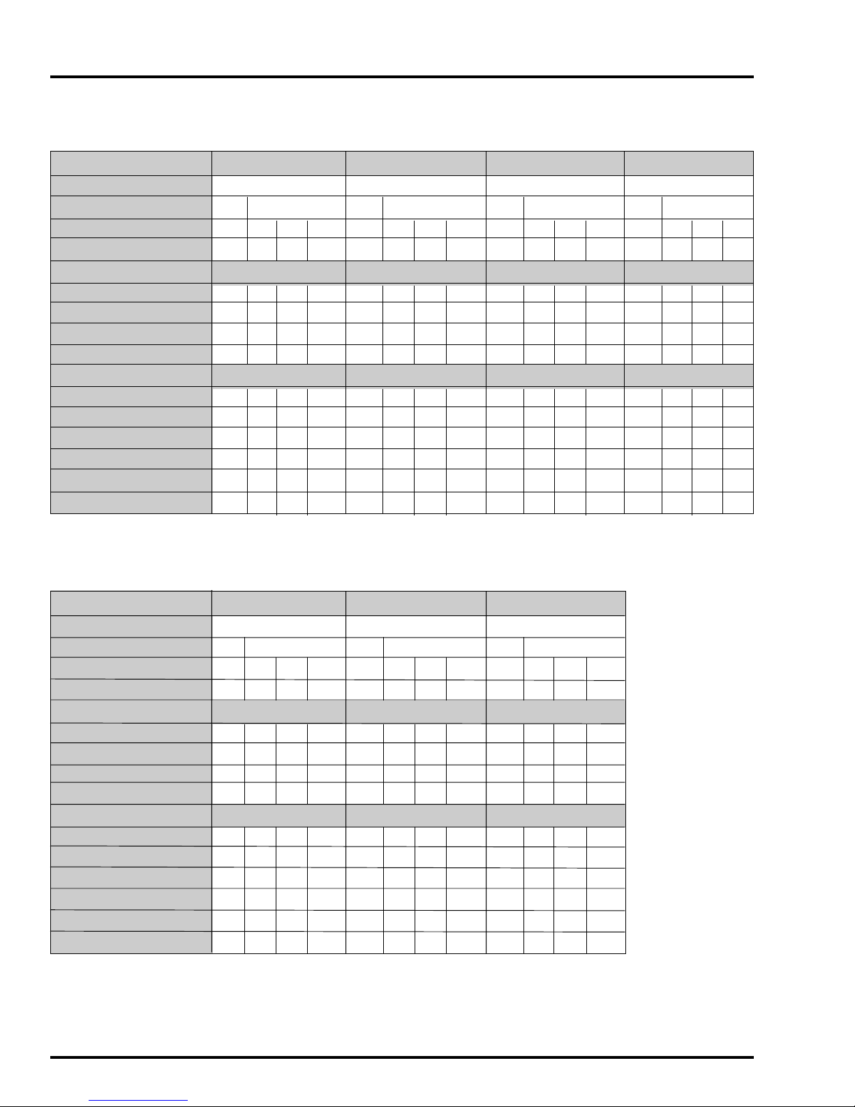
Cross-sectional area of phase
conductors supplying the
equipment S (mm²)
S<=16
16<=S<35
S=>35
Minimum cross-sectional area
of the external protective
conductor (mm²)
S
16
S÷2
9
Fan and Heater TEST STATION
10
Fan and Heater
6
4
2
0
60
80
14
14
14
12
10
15
FAN HORSEPOWER
RPM
PHASE
VOLTS
FULL LOAD AMPS
MINIMUM WIRE SIZE
50' RUN
100' RUN
200' RUN
300' RUN
MINIMUM WIRE SIZE
50' RUN
100' RUN
200' RUN
300' RUN
FUSE SIZE (SLOW BLOW)
BREAKER SIZE
3/4
3450
1
230
5.5
3
230
2.6
460
1.3
575
1.0
Copper Wire
14
14
12
10
14
14
14
14
14
14
14
14
14
14
14
14
Aluminum Wire
14
14
10
8
15
20
14
14
14
12
10
15
14
14
14
14
5
10
14
14
14
14
5
10
1
3450
1
230
5.5
3
230
3.0
460
1.5
575
1.2
Copper Wire
14
14
12
10
14
14
14
14
14
14
14
14
14
14
14
14
Aluminum Wire
14
14
10
8
15
20
14
14
14
14
5
10
14
14
14
14
5
10
1.1/2
3450
1
230
7.5
3
230
4.6
460
2.3
575
1.8
Copper Wire
14
12
8
6
14
14
12
10
14
14
14
12
14
14
14
12
Aluminum Wire
12
10
6
4
15
20
12
12
10
10
10
15
14
12
12
12
5
10
14
14
12
12
5
10
3
3450
1
230
15
3
230
7.4
460
3.7
575
3
Copper Wire
12
10
8
6
12
12
10
8
14
12
12
10
14
12
12
10
Aluminum Wire
12
8
6
4
30
40
12
10
10
8
15
20
12
12
10
10
10
15
12
12
10
10
10
15
FAN HORSEPOWER
RPM
PHASE
VOLTS
FULL LOAD AMPS
MINIMUM WIRE SIZE
50' RUN
100' RUN
200' RUN
300' RUN
MINIMUM WIRE SIZE
50' RUN
100' RUN
200' RUN
300' RUN
FUSE SIZE (SLOW BLOW)
BREAKER SIZE
7
3450
1
230
30
3
230
18
460
9
575
6.9
Copper Wire
10
8
4
4
10
10
8
6
12
12
10
8
12
12
12
10
Aluminum Wire
8
6
3
2
40
60
8
8
6
4
25
30
12
10
10
8
15
15
12
12
10
10
15
15
10
3450
1
230
47
3
230
25
460
13
575
9.6
Copper Wire
8
6
4
2
8
6
4
2
12
10
10
8
12
12
10
8
Aluminum Wire
6
4
2
0
30
40
12
10
8
6
20
20
12
10
10
8
15
20
15
3450
1
230
57
3
230
32
460
16
575
14
Copper Wire
6
4
2
0
6
4
2
0
10
10
10
8
10
10
10
10
Aluminum Wire
4
2
0
00
75
100
4
2
0
00
40
60
8
8
6
4
20
30
8
8
8
6
20
20
3450 RPM Vane Axial Fan
FAN SPECIFICATIONS