3
1 Deutsch
1.1 Allgemeine Angaben
Verwendete Symbole
Symbol Signalwort Bedeutung
Gefahr ! Warnung vor Personenschäden
Achtung ! Warnung vor Sachschäden
⇐Hinweis ! Besondere Funktionen oder Anwendungstipps
9
Handlungsaufforderung
Grundlegende Hinweise
Die Montage- und Betriebsanleitung ist wichtiger Bestandteil der Lieferung und ist an die Personen
gerichtet, die den Motor montieren, betreiben oder warten. Die Anleitung enthält Informationen über
das Produkt und seine sichere Verwendung.
9Bitte lesen Sie die Anleitung sorgfältig durch und beachten Sie insbesondere alle Hinweise, die die
Sicherheit betreffen.
9Bewahren Sie die Anleitung auf.
9Ein zuverlässiger Betrieb und ein Vermeiden von Schäden und Gefahren sind nur bei sorgfältiger
Montage und Einstellung nach der Montageanleitung gegeben.
9Bei unsachgemäß durchgeführter Montage und Installation übernimmt die Fa. Gretsch-Unitas
GmbH Baubeschläge keine Haftung.
9Nach dem Entfernen der Verpackung ist zu prüfen, ob das Gerät vollständig und intakt ist. Plastik-
beutel sowie Kleinteile wie Klammern etc. dürfen nicht in Reichweite von Kindern gelassen werden.
Sie stellen potentielle Gefahrenquellen dar.
Allgemeine Sicherheitshinweise
9Beachten Sie unbedingt die folgenden Sicherheitshinweise.
Zusätzliche Hinweise in den weiteren Kapiteln sind durch die oben beschriebenen Symbole auffällig
gekennzeichnet.
9Lassen Sie die Montage, Installation und Erstinbetriebnahme nur von geschulten, sachkundigen
Personen durchführen.
9Beachten Sie alle für den Einsatzort geltenden Regeln und Bestimmungen, wie z.B.
- Arbeitsschutzvorschriften
- Unfallverhütungsvorschriften
- VDE-Bestimmungen und DIN-Normen
- „Richtlinie für kraftbetätigte Fenster, Türen und Tore“, BGR 232 der Berufgenossenschaft
(bei Bedarf bitte bei Fa. Gretsch-Unitas GmbH Baubeschläge anfordern)
- „Merkblatt KB.01: Kraftbetätigte Fenster“ des Verbandes der Fenster- und Fassadenhersteller
(VFF) (bei Bedarf bitte bei Fa. Gretsch-Unitas GmbH Baubeschläge anfordern)
9Verwenden Sie den Motor nur in technisch einwandfreiem Zustand, bestimmungsgemäß, si-
cherheits- und gefahrenbewusst, unter Beachtung der Montage- und Betriebsanleitung.
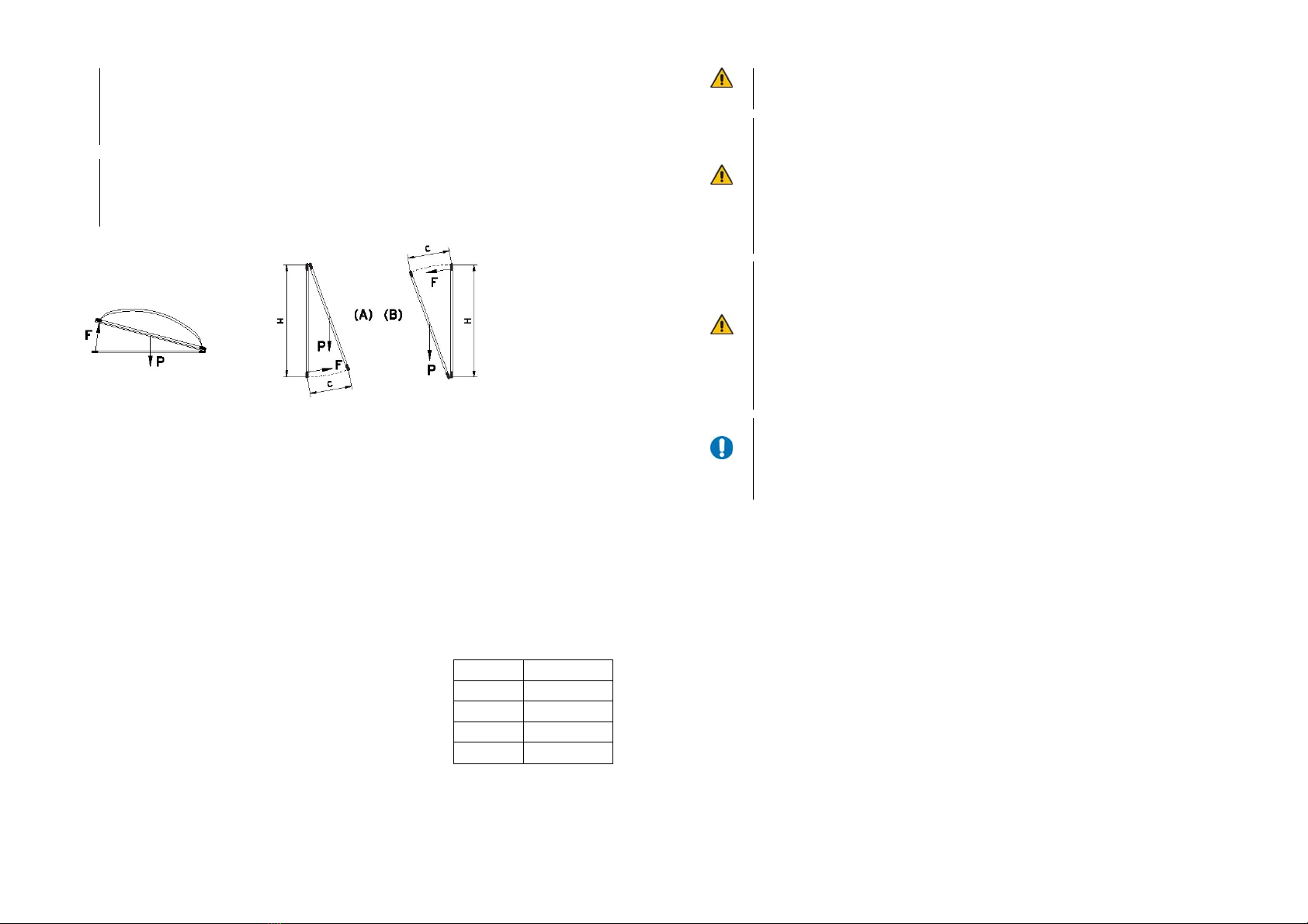
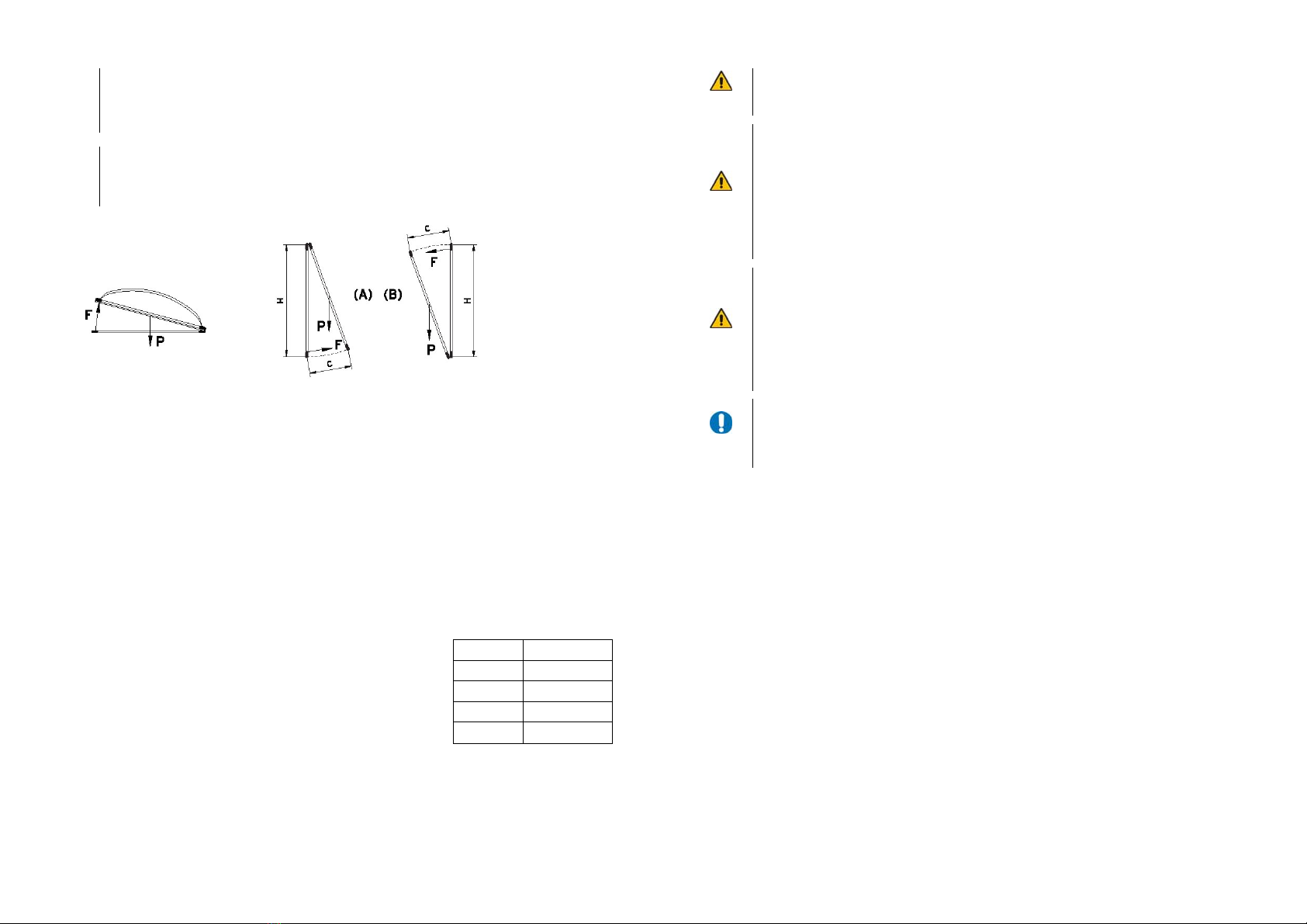
9Bringen Sie Sicherheitseinrichtungen, wie z.B. Fangvorrichtungen oder Sicherheitsscheren sach-
gerecht an und stellen Sie sicher, dass diese funktionsfähig sind. Stellen Sie sicher, dass die Öff-
nungsweite der Fangvorrichtung für den Hub des Kettenantriebs ausreichend ist. 4
9Verwenden Sie nur Original-Ersatzteile, Original-Zubehör und Original-Befestigungsmaterial der
Fa. Gretsch-Unitas GmbH Baubeschläge.
9Benötigtes Befestigungsmaterial ist mit dem Baukörper abzustimmen und wenn nötig zu ergänzen
9Prüfen Sie immer, ob Ihre Anlage den gültigen Bestimmungen entspricht. Besonders zu beachten
sind Öffnungsweite des Fensters, zulässige Einbaumaße, Öffnungsgeschwindigkeit, Druckkraft,
Querschnitt der Anschlussleitung in Abhängigkeit von Leitungslänge und Stromaufnahme.
9Der Antrieb ist ausschließlich zur Installation in trockenen Räumen bestimmt. Schützen Sie den
Antrieb dauerhaft vor Schmutz und vor Feuchtigkeit.
Bestimmungsgemäße Verwendung
Der Kettenmotor ELTRAL K60-300N und ELTRAL K60-300N Synchro ist ausschließlich für das Öffnen
und Schließen von Kipp-, Klapp-, Dreh-, Dach-, Schwing-, und Wendefenstern vorgesehen. Eine
andere oder darüber hinaus gehende Verwendung gilt als nicht bestimmungsgemäß.
Für Schäden, die durch andere Verwendung entstehen, haftet die Fa. Gretsch-Unitas GmbH Baube-
schläge nicht.
Die Gewährleistung erlischt dadurch.
Beschreibung von ELTRAL K60-300N und ELTRAL K60-300N Synchro
Der Kettenmotor ELTRAL K60-300N und ELTRAL K60-300N Synchro ist zum Einsatz in trockenen
Räumen bestimmt mit einer maximal zulässigen Umgebungstemperatur von -5°C bis +75°C. Der
Einbau kann sowohl in horizontaler als auch in vertikaler Lage erfolgen.
•Kettenantrieb mit Edelstahlkette und elektronisch geregelter Soft-Lastabschaltung sowie geringem
Stromverbrauch
•Naturfarben eloxiertes Antriebsgehäuse (E6/EV1) in Schutzart IP32 (Sonderfarbe auf Wunsch)
•Die Einbindung in eine Schließfolgesteuerung ist möglich
•Optimierung der Laufruhe durch stufenlose Einstellung der Kettenvorspannung
•Zur Montage kann mit dem Entriegelungsstecker die Kette entriegelt werden
•Der Antrieb ist neben dem Tandembetrieb auch für den Tridembetrieb an einem Flügel geeignet
(bei Bestellung angeben)
Eine Garnitur ELTRAL K60-300N besteht aus:
•Kettenantrieb mit Anschlusskabel 5m
•Entriegelungsstecker, Blindstopfen, Distanz-
ring, Befestigungsschrauben
•Selbstklebendes Warnzeichen
•Montage und Bedienungsanleitung
Eine Garnitur ELTRAL K60-300N Synchro
besteht aus:
•2x Kettenantrieb mit Anschlusskabel 5m
•Entriegelungsstecker, Blindstopfen, Distanz-
ring, Befestigungsschrauben
•Selbstklebendes Warnzeichen
•Montage und Bedienungsanleitung
Folgende Varianten der Montage sind möglich:
•aufgesetzt auf dem Rahmen,
•aufgesetzt auf dem Flügel,
⇐
Hinweis!
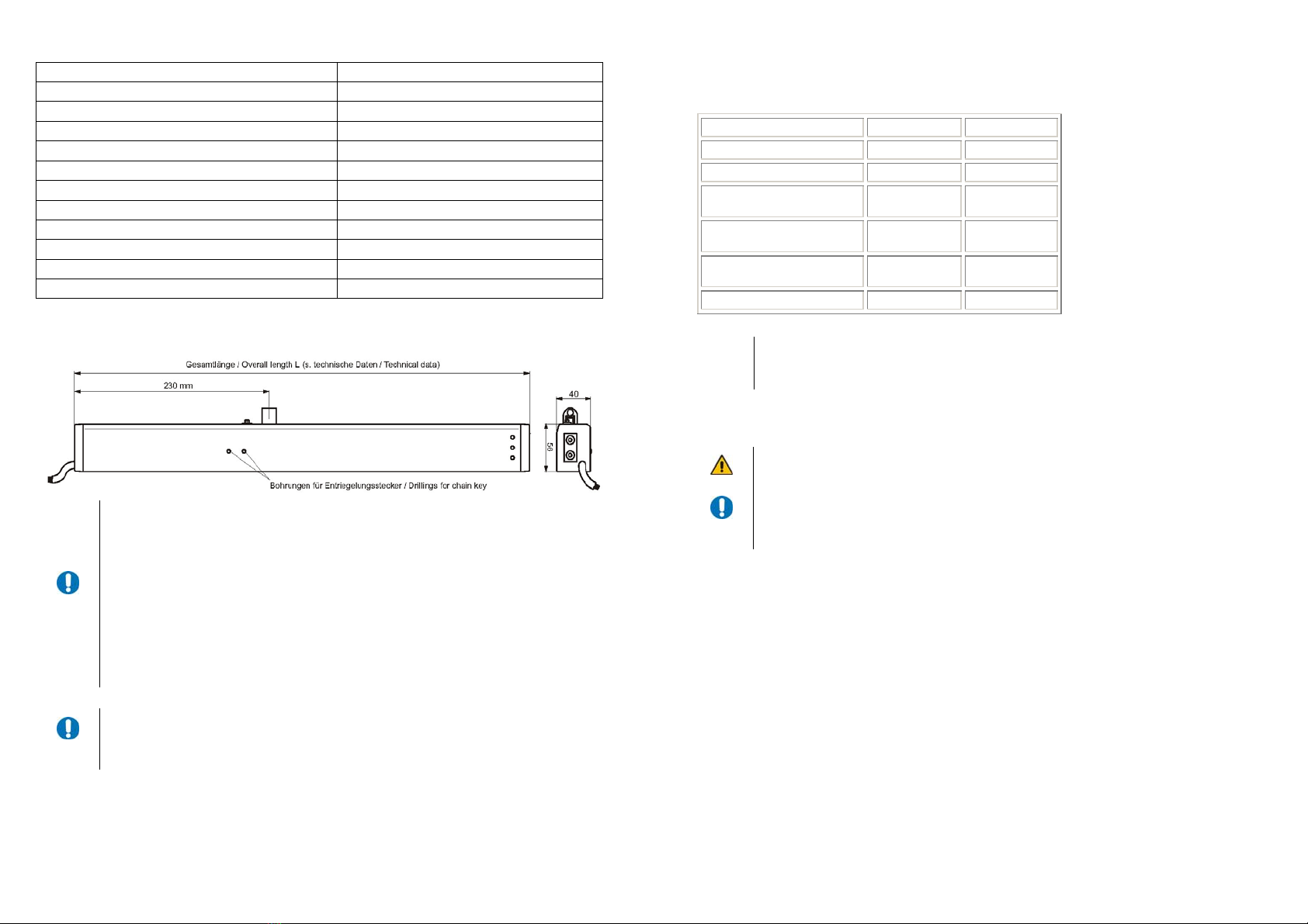
Typenschild
Das Typenschild ist auf dem Motor angebracht. Es ist in eingebautem
Zustand nicht mehr zu erkennen.