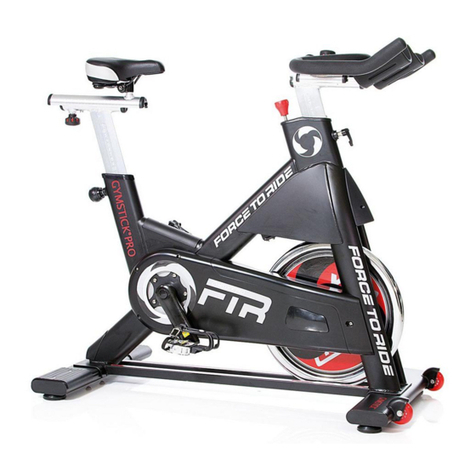
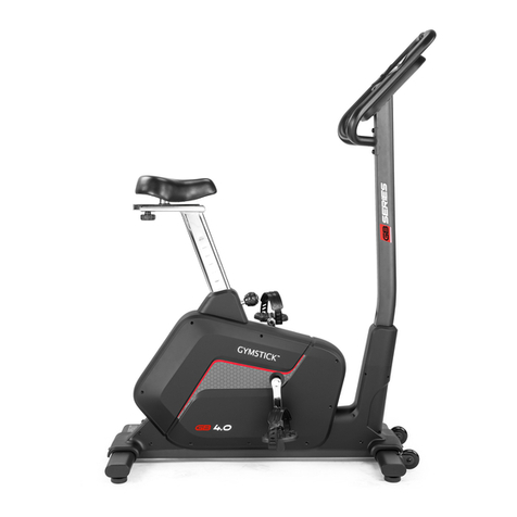
Gymstick 6100 User manual

6100 Exercise bike
Owner’s Manual
5/2012

1
TABLE OF CONTENTS
SAFETY INSTRUCTIONS 2
COMPUTER OPERATION 3
PARTS LIST 4
HARDWARE PACKING LIST 5
OVERVIEW DRAWING 6
ASSEMBLY INSTRUCTIONS 7
IMPLIED WARRANTY 10

2
SAFETY INSTRUCTIONS
Basic precautions should always be followed, including the following safety
instructions when using this equipment: Read all instructions before using this
equipment.
1. Read all the instructions in this manual and do warm up exercises before using this
equipment.
2. Before exercise, in order to avoid injuring the muscle, warming-up is recommended.
3. Please make sure all parts are well fixed before use. This equipment should be placed
on a stable surface. Using a mat or other covering material under the machine
recommended.
4. Please wear proper clothes and shoes when training; do not wear clothes that might be
caught into any part of the equipment.
5. Do not attempt any maintenance or adjustments other than those described in this
manual. Should any problems arise, discontinue use and consult an Authorized
Service Representative.
6. Be careful when step on or off the pedal - always take support on the handlebar first.
7. Do not use the equipment outdoors.
8. This equipment is for home use only.
9. Only one person should train on the equipment at one time.
10. Keep children and pets away from the equipment. This machine is designed for adults
only. The minimum free space required for safe operation is not less than two meters.
11. If you feel any chest pains, nausea, dizziness, or short of breath, you should stop
exercising immediately and consult your physician before continuing.
12. The maximum user weight for this product is 110kgs.
WARNING:
Before beginning any exercise program consult your
physician. This is especially important for the persons who are over 35 years old or
who have pre-existing health problems. Read all instructions before using any
fitness equipment.
CAUTION:
Read all instructions carefully before using this product.
Retain this Owner’s Manual for future reference.

3
COMPUTER OPERATION
FUNCTION MARK
1. SCAN 2.SPEED 2.DIST 4.TIME 5.ODO 6.CAL 7.PULSE
FUNCTIONS AND OPERATIONS:
MODE:
::
:Press Mode to choose functions
AUTO ON /OFF:
The monitor will start automatically when the machine is in motion. A stop over 4 minutes
will turn off the monitor automatically.
SCAN: Press the button until the monitor displays SCAN. Monitor will automatically rotate
display SPEED, DIST, TIME, ODO & CAL in intervals of 30 seconds. Each value will show
for 6 seconds.
SPEED: Press the button until the arrow points to SPEED. Monitor will show the current
speed.
DISTANCE: Press the button until the arrow points to DIST. Monitor will show the current
distance.
TIME: Press the button until the arrow points to TIME. Monitor will count up your exercising
time.
ODOMETER: Press the button until the arrow points to ODO. Monitor will display the total
accumulated distance.
CALORIE: Press the button until the arrow points to CAL. Monitor will accumulate the
calorie consumption (estimation).
PULSE: Press the button until the heartbeat symbol shows. The monitor will display your
current pulse.
SPECIFICATION:
Auto Scan Every 6 seconds
Speed Unit: KPH (km per hour)
Distance 0.0-999.9 Km
Time 0:00-99:59 (Minute: Second)
Odometer 0.0-999.9 Km
Calorie 0.0-999.9 Kcal
FUNCTION
Pulse 40-240 BPM
Sensor No-contact magnetic type
Battery type Two pieces of SIZE-AA A or UM-4
Operation temperature 0℃- +40℃( 32℉- 104℉)

4
PARTS LIST
No.
Description Qty
No.
Description Qty
001 M in Fr me 1 031 Adjust ble Bolt M6x36 2
002 H ndleb r Ø25x1.5 1 032 Hex Nut M6 2
003 H ndleb r Post Ø50x1.5 1 033 Spring W sher Ø6 2
004 Re r St bilizer Ø50x1.5 1 034 C p Nut M10 4
005 Flywheel Ø230,4kg 1 035 Bolt M10x57 4
006 Front St bilizer Ø50x1.5 1 036 Big Curve W sher Ø10 4
007 Tension Control Knob 1 037 Curve W sher Ø16 x Ø8 2
008 Round Knob M16 1 038 W sher Ø8 5
009 Belt 330/J6 1 039 Bolt M8x10 1
010 Computer 1 040 P n He d Phillips Self T pping
Screw ST4.2x25
5
011 Nut M10x1 2 041
P n He d Phillips Self Drilling Screw
ST4.2x20
4
012 Bushing Ø50x1.5 1 042 Locknut M8 3
013 Left Cover 1 043 Be ring 6000zz 2
014 Right Cover 1 044 Pressing Belt Wheel 1
015 Screw ST4.2x15 2 045 Bolt M6x10 1
016 Ring 1 046 Big Curve W sher Ø50x1.5 1
017 Axle Sleeve 7/8” 1 047 Bolt M5x10 2
018 Nut 7/8" 1 048 W sher Ø25 1
019 Belt Pulley with Cr nk 240J6 1 049 H ndleb r End C p Ø25 2
020 Left Foot Ped l YH-30X 1 050 H ndleb r Fo m Grip
Ø30xØ24x455
2
021 Right Foot Ped l YH-30X 1 051 Screw ST4.2x20 2
022 Axle Bush 2 052 W sher Ø6 1
023 B ll Be ring 2 053 H nd Pulse Sensor with Wire
L=750mm
2
024 Bolt M8x15 S6 6 054 Tension C ble L=600mm 1
025 Se t Post 1 055 Curve W sher Ø20 x Ø8 4
026 Sensor with Wire L=450mm 1 056 Bolt M8x70 1
027 Se t Cushion 1 057 Bolt M5x45 1
028 Front St bilizer End C p Ø50 2 058 Axle Sleeve 15/16” 1
029 Re r St bilizer End C p Ø50 2 059 Decor tion Cover 2
030 U Br cket 2 060 Middle Section Sensor Wire
L=800mm
1
5
HARDWARE PACKING LIST
BoltM10*57
PCS
Arc Washerφ
PCS
NUTM10
PCS
Wrench Wrench
Wrench

6
OVERVIEW DRAWING

7
ASSEMBLY INSTRUCTIONS
1. Insta the Front/Rear Stabi izers and Foot Peda s.
Att ch the Front St bilizer (6) onto the front curve pl te of the M in Fr me (1) with two M10
C p Nuts (34), M10x57 Bolts (35), nd Ø10 Big Curve W shers (36).
And mount the Re r St bilizer (4) s me s the Front St bilizer (6)
Connect the Left Foot Ped l (20) to the left Cr nk (19). Thre d it into the cr nk ssembly in
the counterclockwise direction by the tool provided.
Connect the Right Foot Ped l (21) to the right Cr nk (19) by thre ding it in the clockwise
direction.
NOTE: The Left nd Right Foot Ped ls (20, 21) nd Cr nk (19) re m rked with “L” & “R” (left
nd right).

8
2. Insta the Seat Cushion and Seat Post.
Remove three M8 Locknuts (42) nd Ø8 W shers (38) from underne th of the Se t Cushion
(27). Then tt ch the Se t Cushion (27) onto the tri ngle pl te of Se t Post (25) with three
M8 Locknuts (42) nd Ø8 W shers (38) th t were removed.
Insert the Se t Post (25) into the bushing on the tube of the M in Fr me (1) nd then tt ch
the Round Knob (8) onto the tube of the M in Fr me (1) by turning it in clockwise
direction to lock the Se t Post (25) in the suit ble position.
Adjusting the seat post:
Turn the Round Knob (8) in counterclockwise direction until it c n be pulled out. Pull out
the Round Knob (8) nd then slide the Se t Post (25) up or down direction to the suit ble
position. Lock the Se t Post (25) in pl ce by rele sing the Round Knob (8) nd sliding the
Se t Post (25) up or down slightly until the Round Knob (8) "pops" down into the locked
position. For dded s fety, tighten the Round Knob (8) in clockwise direction.

9
3. Insta the Hand ebar Post and Tension Contro Knob.
Remove three M8x15 Bolt (24), Ø8 Curve W sher (55), from the tube of the M in Fr me (1).
Insert the Tension C ble (54) through into the bottom hole of H ndleb r Post (3) nd pull it
out from the squ re hole of H ndleb r Post (3). Connect the Sensor Wire (26) from the
M in Fr me (1) to the Middle Section Sensor Wire (60) from the H ndleb r Post (3).
Insert the H ndleb r Post (3) onto the tube of the M in Fr me (1) nd secure with three
M8x15 Bolt (24), Ø8 Curve W sher (55) th t were removed. Be c reful not to pinch the
c bles inside the H ndleb r Post (3) when turning the Bolts.
Put the c ble end of resist nce c ble of Tension Control Knob (7) into the spring hook of
Tension C ble (54) s shown in dr wing A of figure 3.
Pull the resist nce c ble of Tension Control Knob (7) up nd force it into the g p of met l
br cket of Tension C ble (54) s shown in dr wing B of figure 3. Att ch the Tension
Control Knob (7) onto the H ndleb r Post (3).
4. Insta the Hand ebar and Computer.
Remove two M8x15 Bolts (24) nd Ø8 Curve W shers (37) from the H ndleb r Post (3).
Insert the H nd Pulse Sensor Wires (53) into the hole on the H ndleb r Post (3) nd then
pull them out from the top end of the H ndleb r Post (3).
Att ch the H ndleb r (2) onto the H ndleb r Post (3) with two M8x15 Bolts (24) nd Ø8
Curve W shers (37) th t were removed.
Remove Two M5x10 Bolts (47) from the Computer (10). Connect the H nd Pulse Sensor
Wires (53) nd Middle Section Sensor Wire (60) to the wires th t come from the Computer
(10). Then tt ch the Computer (10) onto the top end of the H ndleb r Post (3) with Two
M5x10 Bolts (47) th t were removed.

10
Implied warranty
The importer of this machine assures that this device is manufactured with high quality
materials.
The prerequisite for the implied warranty is the proper setup in accordance with the
operating instructions. Improper use and /or incorrect transportation can void the warranty.
The implied warranty is valid for 1 year, beginning from the date of purchase. For eventual
defects please contact the dealer of this product within the guarantee period. The warranty
applies to the following parts (as far as included in the scope of delivery): Frame, cable,
electronic devices, wheels, pedals.
The guarantee does not cover:
• Damage effected by outer force
• Intervention by unauthorized parties
• Incorrect handling of the product
• Non-compliance of the operating instructions
Wear parts and expendable parts are also not covered.
The device is only intended for home use. The warranty does not apply to commercial use
of any kind.
Manufactured by:
Gymstick International Oy
Ratavartijankatu 11
15170 Lahti, FINLAND
Table of contents
Other Gymstick Exercise Bike manuals

Gymstick
Gymstick PRO20.0 User manual

Gymstick
Gymstick PRO20.0 User manual

Gymstick
Gymstick EB-DESK User manual

Gymstick
Gymstick MINI BIKE 2.0 User manual

Gymstick
Gymstick GB6.0 User manual

Gymstick
Gymstick GB8.0 User manual

Gymstick
Gymstick PRO FTR User manual

Gymstick
Gymstick VAPOR BIKE 10.0 User manual

Gymstick
Gymstick GB4.0 User manual

Gymstick
Gymstick AIR BIKE PRO User manual