manuals.online logo
Brands
  1. Home
  2. •
  3. Brands
  4. •
  5. H3C
  6. •
  7. Control Unit
  8. •
  9. H3C PSR250-12A User manual

H3C PSR250-12A User manual

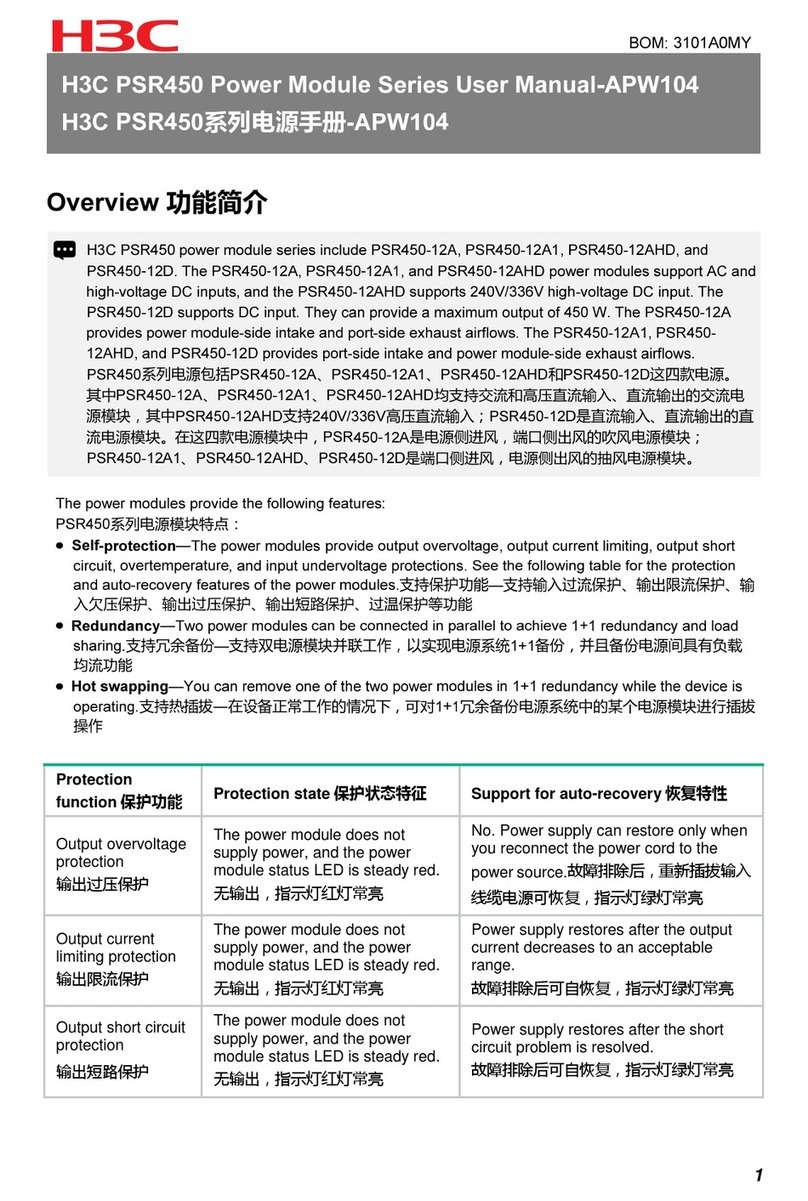
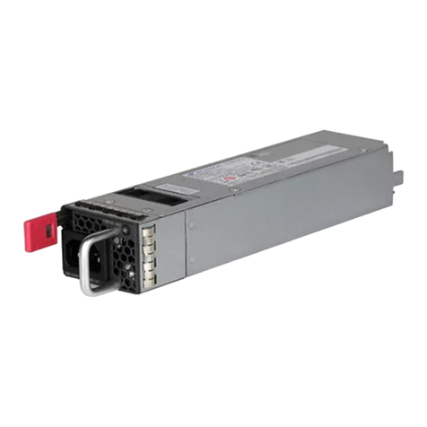
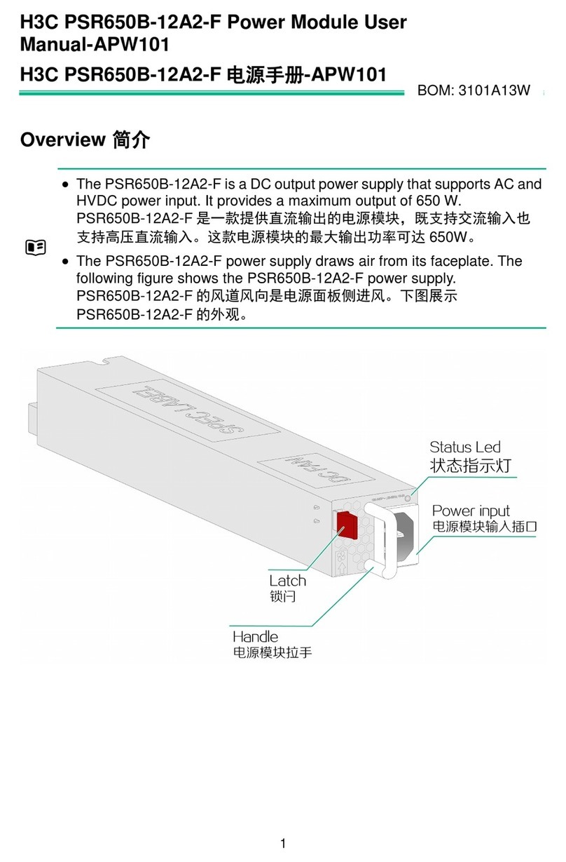
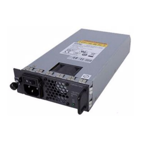
The PSR250-12A and PSR250-12A1 power modules support AC and high-voltage DC inputs. They
can provide a maximum output of 250 W. The PSR250-12A provides power module-side intake and
port-side exhaust airflows, and the PSR250-12A1 provides port-side intake and power module-side
exhaust airflows.
PSR250-12A和PSR250-12A1均是交流或高压直流输入、直流输出的电源模块;最大输出功率可达
250W。两款电源模块的区别是:PSR250-12A是电源侧进风,端口侧出风的吹风电源模块;PSR250-
12A1是端口侧进风,电源侧出风的抽风电源模块。
Functions 功能简介
Technical specifications 电源模块规格
The power module provides the following features:
电源模块特点:
Self-protection—The power modules provide output overvoltage, output current limiting, output short
circuit, overtemperature, and input undervoltage protections. See the following table for the protection
and auto-recovery features of the power modules.
支持保护功能—支持输入过流保护、输出限流保护、输入欠压保护、输出过压保护、输出短路保护、过温
保护等功能。
Redundancy—Two power modules can be connected in parallel to achieve 1+1 redundancy and load
sharing.
支持冗余备份—支持双电源模块并联工作,以实现电源系统1+1备份,并且备份电源间具有负载均流功能。
Hot swapping—You can remove one of the two power modules in 1+1 redundancy while the device is
operating.
支持热插拔—在设备正常工作的情况下,可对1+1冗余备份电源系统中的某个电源模块进行插拔操作。
H3C PSR250-12A & PSR250-12A1 Power Modules User Manual-6PW105
H3C PSR250-12A & PSR250-12A1 电源手册-6PW105
BOM: 3101A0MW
Whether the power module supports high-voltage DC input depends on the device model. For
information, see hardware information and specifications for the device.
电源模块应用于不同设备上时,是否支持高压直流输入与设备型号有关,具体支持情况请参见设备配
套硬件描述。
Item 项目 Specifications 规格
AC input
交流输入
Rated input voltage
额定输入电压范围 100 to 240 VAC @ 50 or 60 Hz
High-voltage DC input
高压直流输入
Rated input current
额定输入电流 4 A
Output voltage
输出电压
Max input voltage
最大输入电压范围 90 to 290 VAC @ 47 to 63 Hz
Output current
输出电流
Max input current
最大输入电流 5 A
Max output power
最大输出功率
Rated input voltage
额定输入电压范围 240 VDC
Rated input current
额定输入电流
Max input voltage
最大输入电压范围
Max input current
最大输入电流
2 A
180 to 320 VDC
2.5 A
Dimensions (H × W × D)
外形尺寸(高×宽×深)
Operating temperature
工作环境温度
Relative humidity
相对湿度
12 V/3.3 V
20.9 A (12 V)/2 A(3.3 V)
250 W
40.2 × 50.5 × 221 mm (1.58 × 1.99 × 8.70 in)
–10°C to +55°C (14°F to 131°F)
5% to 95%
Protection function
保护功能
Protection state
保护状态特征
Support for auto-recovery
恢复特性
Output overvoltage
protection
输出过压保护
The power module does not
supply power, and the power
module status LED is steady red.
无输出,指示灯红灯常亮
No. Power supply can restore only
when you reconnect the power cord
to the power source.
故障排除后,重新插拔输入线缆电源
可恢复,指示灯绿灯常亮
Output current
limiting protection
输出限流保护
The power module does not
supply power, and the power
module status LED is steady red.
无输出,指示灯红灯常亮
Power supply restores after the output
current decreases to an acceptable
range.
故障排除后可自恢复,指示灯绿灯常亮
Output short circuit
protection
输出短路保护
The power module does not
supply power, and the power
module status LED is steady red.
无输出,指示灯红灯常亮
Power supply restores after the short
circuit problem is resolved.
故障排除后可自恢复,指示灯绿灯常亮
Overtemperature
protection
过温保护
The power module does not
supply power, and the power
module status LED is steady red.
无输出,指示灯红灯常亮
Power supply restores after the output
current decreases to an acceptable
range.
故障排除后可自恢复,指示灯绿灯常亮
Input undervoltage
protection
输入欠压保护
The power module does not
supply power, and the power
module status LED is flashing red.
无输出,指示灯红灯闪烁
Power supply restores after the output
current decreases to an acceptable
range.
故障排除后可自恢复,指示灯绿灯常亮
1
2
Appearance 电源模块示意图
A PSR250-12A/PSR250-12A1 has a status LED on its front panel. The following table lists the LED
status and description.
PSR250-12A和PSR250-12A1电源模块面板上都有一个电源模块指示灯,用于指示电源的输入、输出
状态。指示灯在不同情况下的状态及所表示的含义,如下表所示。
LEDs 电源模块状态指示灯
A blue latch indicates power module-side intake and port-side exhaust airflow. A red latch indicates port-
side intake and power module-side exhaust airflow.
锁闩为蓝色,表示电源侧进风、端口侧出风。锁闩为红色,表示端口侧进风、电源侧出风。
PSR250-12A
PSR250-12A1
Power receptacle
电源模块输入插口
Handle
电源模块拉手
Status LED
电源模块状态指示灯
Latch (red)
锁闩(红色)
Power receptacle
电源模块输入插口 Handle
电源模块拉手
Status LED
电源模块状态指示灯
Latch (blue)
锁闩(蓝色)
LED status 指示灯状态 Description 含义
Steady green
绿色常亮
The power module is operating correctly.
电源模块工作正常
Flashing green
绿色闪烁
The power module has power input but is not installed in the device.
当前电源模块有电流输入(电源模块输入正常,但未安装到设备上,
此时电源模块的指示灯会绿色闪烁)
Steady red
红色常亮
The power module has failed or entered protection state.
电源模块出现故障或进入保护状态
Red/Green flashing
alternatively
红色/绿色交替闪烁
The power module has generated an alarm for power problems
(such as output overcurrent, output overload, and overtemperature),
but has not entered protection state.
电源模块告警(电源模块出现了如下情况,但还没有进入保护状态:
输出过流、输出功率过载、过温等)
Flashing red
红色闪烁
The power module does not have power input. If two power
modules are installed and only one power module has power input,
the status LED of the power module that does not have power
input flashes red.
当前电源模块没有电流输入(设备安装有两块电源模块,如果其中
一块电源有电流输入、另一块电源无电流输入,此时无电流输入的
电源模块的指示灯会红色闪烁)
The power module is in input undervoltage protection state.
输入欠压保护
Off
灭
The power module does not have power input.
电源模块没有电流输入
3
4
Tools 工具准备
No ESD wrist strap is provided with the power module. Prepare it yourself.
安装和拆卸电源模块和电源线过程中需要佩戴防静电腕带,请用户自行准备。
Installing and removing a power module
电源模块的安装与拆卸
①Put on the ESD wrist strap, and make sure the strap makes good skin contact and is reliably grounded.
佩戴防静电腕带,请确保防静电腕带与皮肤良好接触,并确认防静电腕带已经良好接地。
②Remove the filler panel, if any, from the target power module slot. Keep the removed filler panel secure
for future use.
若准备安装电源模块的电源槽位上有电源假面板,则在安装电源模块前请先拆卸电源假面板。请善保管
电源模块插槽的假面板,以备将来需要时使用。
③Unpack the power module and verify that the power module model is as required. Keep the packaging
box and bag secure for future use.
从电源模块包装盒中取出电源模块,确认电源模块的型号与所需一致。请善保管电源模块的包装盒、包
装袋等物品,以备将来需要时使用。
④Correctly orient the power module. Holding the power module handle with one hand and supporting the
power module bottom with the other, slide the power power module along the guide rails into the slot
until you hear a click.
保证电源模块上下方向正确(电源模块及插槽为防反插结构设计,如果安装方向错误,电源模块将不能
完全插入到插槽中),用一只手握住电源模块上的拉手,另一只手托住电源模块底部,将其后端对准电
源插槽,将电源模块沿电源插槽水平插入插槽。当电源模块完全插入到插槽时,会听到电源模块上的锁
闩卡住插槽的声音。
Installing the power module 安装电源模块
To avoid bodily injury or device damage, follow the steps in the following figure to install the power
module.
电源模块的安装过程应严格按照下图顺序进行,否则可能会对设备造成损坏或对人身造成伤害。
Install the power module
安装电源模块
Connect the power cord
连接电源线
Turn on the circuit breaker
连通电源输入端断路器
Make sure the power module makes good contact with the backplane of the device.
插入电源模块的过程中,可以借助轻微的惯性将其插入插槽,从而保证电源后端与背板插口良好接触。
The power module is foolproof. If the power module is oriented incorrectly, you cannot install the
power module into the slot. To avoid damaging the terminals on the power module, if you
encounter a hard resistance while inserting the power module, pull out the power module, reorient
it, and then insert it again.
为了避免损坏或弯曲电源端子,在插入过程中,如果位置没有对正,请先将电源模块拉出,调整位
置后再重新插入。
The installation and removal procedures for the PSR250-12A and PSR250-12A1 are similar.
This section takes the PSR250-12A for example. PSR250-12A和PSR250-
12A1两款电源模块的安装与拆卸的操作步骤基本相同,本手册以PSR250-
12A电源模块为例进行介绍。
Make sure the power module is compatible with the device. For more information about the
compatibility matrix, see the installation guide of the device.
安装前请检查电源模块型号与设备是否匹配,具体请参见各产品的安装指导。
Safety guidelines 安全注意事项
To prevent device damage and bodily injury, follow these restrictions and guidelines when you install
or remove the power module:
为避免对电源模块和设备造成损坏及对人身的伤害,请遵从以下的注意事项:
Before you install a power module, make sure its airflow direction is as required.
在安装电源模块以前,请确认电源模块气流方向和安装环境的通风要求一致。
Do not install power modules that provide different directions of airflow on the same device.
不同风向的电源模块不要混插在同一台设备上。
Always wear an ESD wrist strap and make sure it makes good skin contact.
在安装和拆卸电源模块时,请佩戴防静电腕带,并确保防静电腕带与皮肤良好接触。
Before installing the power module, make sure the voltage of the power supply system is as
required by the power module, and the output voltage of the power module is as required by the
device.
在安装电源模块以前,请确保外置供电系统的工作电压与电源模块所标电压、电源模块输出电压与
设备所需电压一致。
Do not touch any bare cables or terminals of the power module.
请不要接触电源模块中露出的任何导线、端子部分。
Do not place the power module in a wet area, and prevent liquid from flowing into the power
module.
请不要将电源模块放置在潮湿的地方,也不要让液体进入电源模块内部。
To avoid power module damage, do not open the power module. When the internal circuits or
components of the power module fail, contact H3C Support.
为了防止电源模块受损,请不要随意打开电源模块外壳,当电源模块内部线路或元器件出现故障时,
请移交维修人员进行检修。
5
6
③Connect the other end of the power cord to the power supply system, and turn on the circuit breaker of
the power supply system.
将电源线的另一端插到外置交流供电系统或者外置高压直流供电系统的插座上,并连通电源输入端的断
路器。
④Examine the LED on the power module. If the LED is steady green, the power cord is successfully
connected. If the LED is off or red, examine the installation conditions, troubleshoot the problems, and
try again until the LED becomes steady green.
查看电源模块的状态指示灯,如果指示灯的状态为绿色常亮,说明电源线连接成功。如果指示灯不亮或
为红色,请仔细检查安装情况,排除各种故障后,再次尝试,直到电源模块状态指示灯正常为止。
Removing the power module 拆卸电源模块
To avoid bodily injury or device damage, follow the steps in the following figure to remove the power
module.
电源模块的拆卸过程应严格按照下图顺序进行,否则可能会对设备造成损坏或对人身造成伤害。
①Turn off the circuit breaker of the power cord.
断开电源输入端断路器。
②Put on the ESD wrist strap, and make sure the strap makes good skin contact and is reliably
grounded.
佩戴防静电腕带,请确保防静电腕带与皮肤良好接触,并确认防静电腕带已经良好接地。
③Loosen the cable tie, and take off the power cord.
松开固定电源线的可拆卸式扎带,取下电源线。
④Holding the power module handle with one hand, use your thumb to press the latch towards the
handle and simultaneously pull the power module outward using force parallel to the ground. After
pulling the power module part way out, hold the power module bottom with the other hand, and pull the
power module slowly out of the slot along the guide rails.
一只手握住电源模块上的拉手,用拇指向拉手侧掰动锁闩,同时沿插槽水平向外拉动电源模块,将模块
拉出来一部分后,用另一只手托住电源模块底部,将电源模块缓慢拉出。
⑤Put the removed power module on an antistatic mat or into its initial package.
将拆卸下来的电源模块放置到防静电垫子上或电源模块的包装袋中。
②Use a cable tie to secure the power cord to the handle of the power module.
用可拆卸式扎带将电源线固定到电源模块的拉手处,以防电源线脱落。
①Connect the female connector on the power cord to the power receptacle on the device.
将电源线带插孔的一端插到电源模块的输入插口上。
Turn off the circuit breaker
断开电源输入端断路器
Remove the power cord
拆除电源线
Remove the power
module
拆卸电源模块
If you are not to install a power module in the slot, install a filler panel in the slot to prevent dust from
entering the chassis.
如果该电源插槽中不再安装电源模块,请将电源模块插槽的假面板安装到该插槽上,以免灰尘进入机箱。
Make sure each power cord has a separate circuit breaker.
请保证电源线有独立的输入断路器。
Turn off the circuit breaker before connecting the power cord.
连接电源线前,请将需要连接电源线的输入端断路器置于断开状态。
Copyright © 2023, New H3C Technologies Co., Ltd.
The information in this document is subject to change without notice.
Copyright © 2023 新华三技术有限公司 版权所有,保留一切权利
本文档中的信息如有更改,恕不另行通知
如需了解产品及安装方面的更多信息,请登录H3C网站 www.h3c.com
Connecting the power cord 连接电源线
12
2
1
7

This manual suits for next models

1

Other H3C Control Unit manuals

H3C LSQM1TGT24FD0 User manual

H3C

H3C LSQM1TGT24FD0 User manual

H3C LSQM1CGS2QSA0 User manual

H3C

H3C LSQM1CGS2QSA0 User manual

H3C SIC-4G-CAT6 User manual

H3C

H3C SIC-4G-CAT6 User manual

H3C NSQM1FWDFGC1 User manual

H3C

H3C NSQM1FWDFGC1 User manual

H3C PSR250-12A1 User manual

H3C

H3C PSR250-12A1 User manual

H3C PSR3000-54A User manual

H3C

H3C PSR3000-54A User manual

H3C MSR Router Comware 5 Series User manual

H3C

H3C MSR Router Comware 5 Series User manual

H3C PSR180-56A User manual

H3C

H3C PSR180-56A User manual

H3C PSR3000-54A User manual

H3C

H3C PSR3000-54A User manual

H3C PSR2400-54A User manual

H3C

H3C PSR2400-54A User manual

H3C SecBlade User manual

H3C

H3C SecBlade User manual

H3C LSQM1SDNB0 User manual

H3C

H3C LSQM1SDNB0 User manual

H3C S9500 LSB1FW2A0 Parts list manual

H3C

H3C S9500 LSB1FW2A0 Parts list manual

H3C PSR750-A User manual

H3C

H3C PSR750-A User manual

H3C EWPA1PCID User manual

H3C

H3C EWPA1PCID User manual

H3C SecPath M9000-AI NSQM5MBSHA1 User manual

H3C

H3C SecPath M9000-AI NSQM5MBSHA1 User manual

H3C SecPath AC2500 User manual

H3C

H3C SecPath AC2500 User manual

H3C LSVM1S9800FAN User manual

H3C

H3C LSVM1S9800FAN User manual

H3C LSVM2106SFAN User manual

H3C

H3C LSVM2106SFAN User manual

H3C PSR6000 User manual

H3C

H3C PSR6000 User manual

H3C PSR650C-12A User manual

H3C

H3C PSR650C-12A User manual

H3C PSR2400-12AHAH-B User manual

H3C

H3C PSR2400-12AHAH-B User manual

H3C SR6600 SPE-FWM-200 User manual

H3C

H3C SR6600 SPE-FWM-200 User manual

H3C Campus SeerEngine LSXM1SEERBXC2 User manual

H3C

H3C Campus SeerEngine LSXM1SEERBXC2 User manual

Popular Control Unit manuals by other brands

Telit Wireless Solutions M.2 N930 Series Hardware user's guide

Telit Wireless Solutions

Telit Wireless Solutions M.2 N930 Series Hardware user's guide

FW Murphy M-VIEW J1939 Series user manual

FW Murphy

FW Murphy M-VIEW J1939 Series user manual

Helo WE 40 User and installation manual

Helo

Helo WE 40 User and installation manual

BBQ Guru CyberQII user guide

BBQ Guru

BBQ Guru CyberQII user guide

Quectel BC950N-N1 Hardware design

Quectel

Quectel BC950N-N1 Hardware design

WAGO 750-1415/040-000 manual

WAGO

WAGO 750-1415/040-000 manual

Gemalto Cinterion BGS2-W miniPCIe Hardware interface description

Gemalto

Gemalto Cinterion BGS2-W miniPCIe Hardware interface description

QTS P3 AN-X-TI-MAS user manual

QTS

QTS P3 AN-X-TI-MAS user manual

Speakman SE-362 Installation

Speakman

Speakman SE-362 Installation

Allen-Bradley SLC 500 DeviceNet user manual

Allen-Bradley

Allen-Bradley SLC 500 DeviceNet user manual

N.A.T. NAMC-ZYNQ-FMC manual

N.A.T.

N.A.T. NAMC-ZYNQ-FMC manual

Emerson BM6X Series instruction manual

Emerson

Emerson BM6X Series instruction manual

SVF K8 Series Installation operation & maintenance

SVF

SVF K8 Series Installation operation & maintenance

Phoenix Mecano Dewert Okin HE-300 SMPS installation instructions

Phoenix Mecano

Phoenix Mecano Dewert Okin HE-300 SMPS installation instructions

Omega DB-PASS-23A installation instructions

Omega

Omega DB-PASS-23A installation instructions

DEUTSCHMANN AUTOMATION LOCON 200 instruction manual

DEUTSCHMANN AUTOMATION

DEUTSCHMANN AUTOMATION LOCON 200 instruction manual

GRAS 12BA instruction manual

GRAS

GRAS 12BA instruction manual

Siemens SINUMERIK 808D Diagnostic manual

Siemens

Siemens SINUMERIK 808D Diagnostic manual

manuals.online logo
manuals.online logoBrands
  • About & Mission
  • Contact us
  • Privacy Policy
  • Terms and Conditions

Copyright 2025 Manuals.Online. All Rights Reserved.