H3C NSQ1TGX4EA0 LPU User manual
Other H3C Network Hardware manuals
H3C
H3C WA6300-CMW710-R2444P01 How to use

H3C
H3C XE 200 User manual
H3C
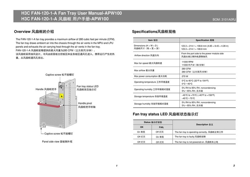
H3C FAN-120-1-A User manual
H3C
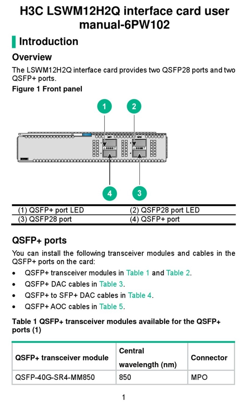
H3C LSWM12H2Q User manual
H3C
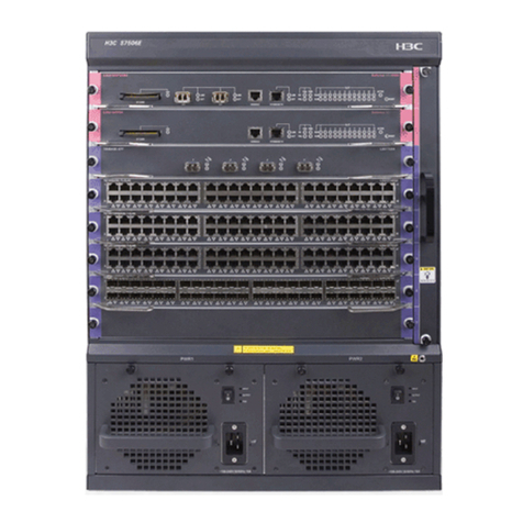
H3C H3C S7500E-X Quick guide
H3C
H3C DHCP User manual
H3C
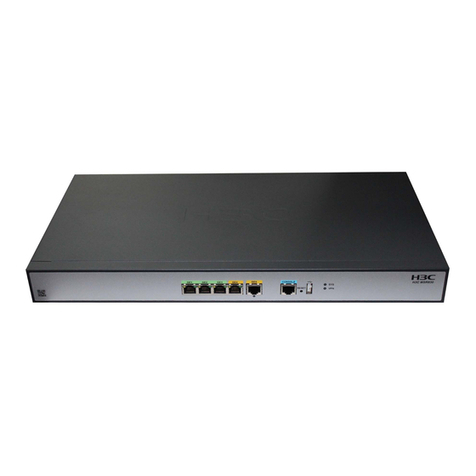
H3C MSR Series Installation manual
H3C
H3C ETH682i User manual
H3C
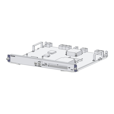
H3C SecPath M9000 NSQ1SUPB0 MPU User manual
H3C
H3C S9500 Series User manual

H3C
H3C SecCenter CSAP-SA User manual
H3C
H3C SecPath L1000-A User manual
H3C
H3C SecPath U200 Series User manual
H3C
H3C 1000BASE-X-SFP User manual
H3C
H3C SecPath F5000-AI-20 User manual
H3C
H3C H3C S7500E Series User manual

H3C
H3C SecPath L5030 User manual
H3C
H3C S7500 Series User manual
H3C
H3C LSQM1BFANSCB User manual
H3C
H3C SecPathT5030 User manual
Popular Network Hardware manuals by other brands

Matrix Switch Corporation
Matrix Switch Corporation MSC-HD161DEL product manual

B&B Electronics
B&B Electronics ZXT9-IO-222R2 product manual

Yudor
Yudor YDS-16 user manual

D-Link
D-Link ShareCenter DNS-320L datasheet

Samsung
Samsung ES1642dc Hardware user manual

Honeywell Home
Honeywell Home LTEM-PV Installation and setup guide
