H3C UniServer BX720EF User manual

Copyright © 2023, New H3C Technologies Co., Ltd. and its licensors
All rights reserved
No part of this manual may be reproduced or transmitted in any form or by any means without prior
written consent of New H3C Technologies Co., Ltd.
Trademarks
Except for the trademarks of New H3C Technologies Co., Ltd., any trademarks that may be
mentioned in this document are the property of their respective owners.
Notice
The information in this document is subject to change without notice. All contents in this document,
including statements, information, and recommendations, are believed to be accurate, but theyare
presented without warranty of any kind, express or implied. H3C shall not be liable for technical or
editorial errors or omissions contained herein.
Environmental protection
This product has been designed to comply with the environmental protection requirements. The
storage, use, and disposal of this product must meet the applicable national laws and regulations.

Preface
This user guide describes specifications and common operations performed on the BX720EF switch
module, such as installing and removing, configuring, and powering on and powering off the switch
module.
This preface includes the following topics about the documentation:
•
Audience.
•
Conventions.
•
Documentation feedback.
Audience
This documentation is intended for:
•
Network planners.
•
Field technical support and servicing engineers.
•
Network administrators working with the server.
Conventions
The following information describes the conventions used in the documentation.
Command conventions
Convention
Description
Boldface Bold text represents commands and keywords that you enter literally as shown.
Italic Italic text represents arguments that you replace with actual values.
[ ] Square brackets enclose syntax choices (keywords or arguments) that are optional.
{ x | y | ... }
Braces enclose a set of required syntax choices separated by vertical bars, from which
you select one.
[ x | y | ... ]
Square brackets enclose a set of optional syntax choices separated by vertical bars,
from which you select one or none.
{ x | y | ... } *
Asterisk marked braces enclose a set of required syntax choices separated by vertical
bars, from which you select a minimum of one.
[ x | y | ... ] *
Asterisk marked square brackets enclose optional syntaxchoices separated by vertical
bars, from which you select one choice, multiple choices, or none.
&<1-n> The argument or keyword and argument combination before the ampersand (&) sign
can be entered 1 to n times.
# A line that starts with a pound (#) sign is comments.
GUI conventions
Convention
Description
Boldface Window names, button names, field names, and menu items are in Boldface. For
example, the New User window opens; click OK.
>
Multi-level menus are separated by angle brackets. For example, File > Create >

Convention
Description
Folder.
Symbols
Convention
Description
WARNING!
An alert that calls attention to important information that if not understood or followed
can result in personal injury.
CAUTION:
An alert that calls attention to important information that if not understood or followed
can result in data loss, data corruption, or damage to hardware or software.
IMPORTANT:
An alert that calls attention to essential information.
NOTE:
An alert that contains additional or supplementary information.
TIP:
An alert that provides helpful information.
Network topology icons
Convention
Description
Represents a generic network device, such as a router, switch, or firewall.
Represents a routing-capable device, such as a router or Layer 3 switch.
Represents a generic switch, such as a Layer 2 or Layer 3 switch, or a router that
supports Layer 2 forwarding and other Layer 2 features.
Represents an access controller, a unified wired-WLAN module, or the access
controller engine on a unified wired-WLAN switch.
Represents an access point.
Represents a wireless terminator unit.
Represents a wireless terminator.
Represents a mesh access point.
Represents omnidirectional signals.
Represents directional signals.
Represents a security product, such as a firewall, UTM, multiservice security
gateway, or load balancing device.
Represents a security module, such as a firewall, load balancing, NetStream, SSL
VPN, IPS, or ACG module.
T
T
T
T

Examples provided in this document
Examples in this document might use devices that differ from your device in hardware model,
configuration, or software version. It is normal that the port numbers, sample output, screenshots,
and other information in the examples differ from what you have on your device.
Documentation feedback
You can e-mail your comments about product documentation to info@h3c.com.
We appreciate your comments.

i
Contents
Safety············································································································1
Safety information··············································································································································1
General operating safety····························································································································1
Electrical safety··········································································································································1
Safety precautions ·············································································································································1
ESD prevention··················································································································································1
Preventing electrostatic discharge·············································································································1
Grounding methods to prevent electrostatic discharge··············································································2
Overview of BX720EF convergent switch module··········································1
Product overview················································································································································1
Reliability····························································································································································1
Device redundancy ····································································································································1
Link redundancy·········································································································································2
Specifications·····················································································································································2
Port·····································································································································································3
Port numbering rules··································································································································3
External ports·············································································································································3
Internal ports··············································································································································5
LEDs ··································································································································································5
Logical structure·················································································································································8
Installation guidelines·········································································································································8
Internal networking ························································································1
Internal connections between ICM and mezzanine network adapter·································································1
Internal connections between ICM and mezzanine network adapter port ·························································3
Hardware compatibility ··················································································3
Compatibility between switch modules and mezzanine network adapters ························································4
Compatibility between switch modules and optical modules/cables··································································4
Replacing the switch module·········································································6
Scenario·····························································································································································6
Installation tools ·················································································································································6
Preparations·······················································································································································7
Replacement procedure·····································································································································7
Powering on and powering off the switch module··········································1
Powering on the switch module ·························································································································1
Supported power-on methods····················································································································1
Operation methods·····································································································································1
Powering off the switch module ·························································································································4
Supported power-off methods····················································································································4
Operation methods·····································································································································4
Configuring the switch module·······································································1
Logging in to the switch module·························································································································1
Obtaining the related data··························································································································1
Login methods············································································································································1
Logging in to the switch module through the SYS serial port (console port)··············································1
Logging in to the SOL serial port through redirection·················································································2
Configuring the management IP address of the switch module·········································································3
Obtaining and planning related data··········································································································3
Configuration methods·······························································································································3
Configuring the management IP address through OM Web interface ·······················································3
Configuring the management IP address through the CLI of the OM module···········································4
Configuring the management IP address through the switch module CLI·················································4


ii
Switching convergent port type··························································································································5
Switching Ethernet ports to FC ports ·········································································································5
Switching FC ports to Ethernet ports ·········································································································5
Configuring services of the switch module·········································································································5
Saving the configuration file·······························································································································6
Common operations···········································································································································7
Logging in to the OM Web interface···········································································································7
Logging in to the OM CLI···························································································································8
Firmware upgrade··························································································1

1
Safety
Safety information
To avoid personal injury or damage to the device, read the following information carefully before you
operate the device. Safety precautions in actual operation include but are not limited to safety
information mentioned in this document.
General operating safety
•
Only H3C authorized or professional engineers are allowed to operate the device.
•
Keep the device clean and dust-free. Do not place it in a humid place or allow liquids to enter it.
•
Before powering on the device, ensure that the blade server chassis is securely grounded.
•
To maintain sufficient heat dissipation, use filler panels on idle slots.
Electrical safety
•
Carefully check any potential hazards in the work area, for example, whether the ground is wet
and whether the blade server chassis is grounded or reliably grounded.
•
Do not work alone when performing live-line maintenance.
•
Do not touch the power supply directly or indirectly through conductive objects to prevent
electric shock.
Safety precautions
•
When maintaining the device, place the device on a clean, stable table or floor.
•
To avoid personal injury from hot surfaces or internal components, allow the device and its
internal components to cool before touching them.
•
When using tools to maintain the device, follow the correct operation methods to avoid damage
to the personnel or device.
•
When connecting, testing or replacing optical fibers, do not look directly into the optical fiber
outlet to prevent the laser beam from hurting your eyes.
•
Gently and slowly transport or place the device with force evenly distributed.
ESD prevention
Preventing electrostatic discharge
Electrostatic charges that build up on people and conductors damage or shorten the lifespan of the
main board and electrostatic-sensitive components.
To prevent electrostatic damage, follow these guidelines:
•
Transport or store the device in an ESD bag.
•
Place the device on a grounded table before taking it out of the ESD bag.
•
Avoid touching pins or circuitry of the device without taking any ESD prevention measures.

2
Grounding methods to prevent electrostatic discharge
When removing or installing the device, you can use one or multiple of the following grounding
methods to prevent electrostatic discharge:
•
Wear an ESD wrist strap and ensure that it is reliably grounded. Ensure that the ESD wrist strap
makes good skin contact and can be flexibly stretched out and draw back.
•
In the work areas, wear the ESD clothing and shoes.
•
Use conductive field service tools.
•
Use a portable field service kit with a folding ESD tool mat.

1
Overview of BX720EF convergent switch
module
Hardware images shown in this document are for illustration only.
This document uses a certain version of software interfaces as examples. The software interfaces
might be updated over time.
ICM modules supported by the blade server chassis are classified into switch modules and
pass-through modules (also known as cascade modules in some documents). BX720EF is a type of
switch module. Both ICMs and switch modules mentioned in this document refer to the BX720EF.
Product overview
As a convergent switching control unit inside the blade server chassis, the H3C UniServer
BX1020EF switch module (BX1020EF for short) provides data switching functions for blade servers
installed in the enclosure and centrally provides external data ports, to achieve the communication
between blade servers and external networks. External ports include Ethernet ports and FC ports.
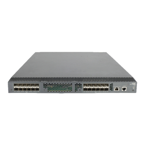
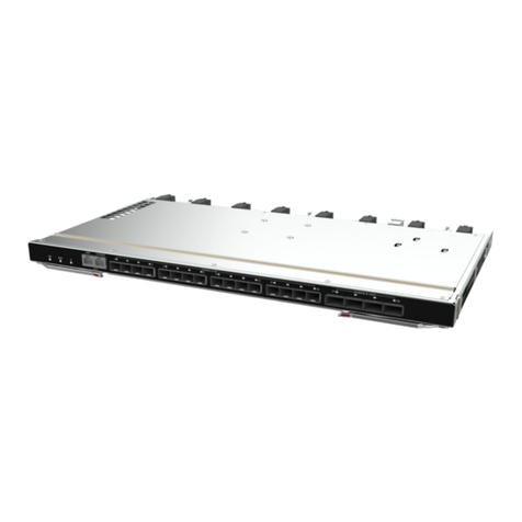
Figure 1 shows the appearance of the BX720EF convergent switch module.
Figure 1 Appearance
Reliability
Device redundancy
The blade server chassis can accommodate up to six switch modules. For information about switch
module installation positions, see Figure 2. Switch modules in slot 1 and slot 4, switch modules in
slot 2 and slot 5, and switch modules in slot 3 and slot 6 are mutually interconnected through internal
interfaces of the switch modules. Each of the three pairs can function as a switch plane. You can
configure these pairs of switch modules in active/standby mode according to service requirements.

2
Figure 2 Slots for installing the switch modules
(1) ICM 1 slot
(2) ICM 2 slot
(3) ICM 3 slot
(4) ICM 4 slot
(5) ICM 5 slot
(6) ICM 6 slot
Link redundancy
The switch modules internally connect to blade servers through the mid-plane. In addition, the switch
modules provide uplink interfaces for the blade servers through the external interfaces of the switch
modules. The switch modules connect to a blade server through two internal interfaces, which
function in active/standby mode, to ensure the reliability of internal links.
Specifications
Table 1 describes the specifications of the switch module.
Table 1 Specifications
Category
Item
Description
Physical
specifications
Dimensions
(H × W × D) 27 × 491.6 × 296.5 mm ( 1.06 × 19.35 × 11.67 in)
Maximum
weight 3.60 kg (7.94 lb)
Power
consumption Maximum
power
110 W

3
consumption
Environment
specifications
Temperature •Operating temperature: 5°C to 45°C (41°F to 113°F)
•Storage temperature: –40°C to +70°C (–40°F to +158°F)
Humidity •Operating humidity: 8% to 90% (non-condensing)
•Storage humidity: 5% to 95% (non-condensing)
Altitude
•Operating altitude: –60 m to +5000 m (–196.85 ft to +16404.20 ft)
(The allowed maximum temperature decreases by 0.33 °C (32.59 °F)
as the altitude increases by 100 m (328.08 ft) from 900 m (2952.76 ft))
•Storage altitude: –60 m to +5000 m (–196.85 ft to +16404.20 ft)
Port
This section describes numbering rules, positions, quantity, and other information about the ports of
the switch module.
Port numbering rules
Ports of the switch module are numbered in three dimensions: A, B, and C.
•
A: Indicates the number of the IRF member device. Since the switch module does not have any
IRF by default, the default value of Ais 1. Devices with the same IRF member ID cannot form an
IRF fabric. To change the member ID of a device, use the irf member renumber command.
•
B: Indicates an internal or external port. 0 indicates an internal port, and 1 indicates an external
port.
•
C: Indicates the sequence number of the port.
External ports
Figure 3 shows the external ports provided by the switch module. Table 2 describes specific
functions of the external ports.

4
Figure 3 External ports
(1) AMC serial port
(2) SYS serial port (Console port)
(3) Convergent port
(4) 10GE optical interface
(5) 40GE optical interface
Table 2 Description of external ports
SN Port Name Port Type Port
Quantity
Description
1 AMC serial port RJ-45 1
Serial port used to enter the AMC
CLI of the switch module. The baud
rate is 115200 bit/s. It is only used by
technical support engineers to
upgrade the AMC firmware.
2 SYS serial port (Console
port) RJ-45 1
Serial port used for local
management, debugging, and
maintenance of the switch module.
The baud rate is 9600 bit/s. You can
log in to the CLI of the switch module
through the SYS serial port.

5
3 Convergent port ZSFP+ 8
•Eight ports are divided into two
groups. Ports 1–4 are in a
group, and ports 5–8 are in a
group.
•Each port can be switched over
between Ethernet port and FC
port. By default, the port works
as an Ethernet port.
•Port switching is conducted in
the unit of groups. You can
uniformly switch a group of
ports from Ethernet ports to FC
ports or from FC ports to
Ethernet ports through the ICM
CLI. For specific switching
methods, see "Switching
convergent port type."
4 10GE optical interface SFP+ 8 Support for FCoE
5 40GE optical interface QSFP+ 4 Support for FCoE
For details about the optical modules and cables supported by the switch module as well as their
specifications, see "Compatibility between switch modules and optical modules/cables."
Internal ports
Table 3 shows the internal port provided by the switch module.
Table 3 Description of the internal port
Port
Name
Port Type Port
Quantity
Description
10GE port N/A 38
•A total of 32 ports are provided to connect to blade servers.
The port number ranges from XGE1/0/1 to XGE1/0/32.
•
Used to connect to switch modules installed in pairs in slots 1
and 4, 2 and 5, and 3 and 6. The ports are numbered from
XGE1/0/33 through XGE1/0/36. The four ports are
connected to each other through the mid plane.As a best
practice, use the ports as physical ports for IRF connection.
•A total of 2 ports are provided to connect toAE modules,
where only switch modules in slot 1 and slot 4, with the ports
numbered XGE1/0/37 through XGE1/0/38, are connected to
the AE modules.
LEDs
Figure 4 shows positions and appearance of LEDs on the switch module. Table 4 describes LED
colors and the corresponding meaning.

6
Figure 4 LEDs
(1) UID LED
(2) RUN LED
(3) Health LED
(4) Port LED
The appearance of all port LEDs of the switch module is identical. The figure takes one port LED for
illustration.
Table 4 Description of LEDs
SN
Name
Color
Status
1 UID LED Blue
•Steady on blue: The UID LED is activated (through the
OM module).
•Flashing blue (at a frequency of 1 Hz): The switch
module is under remote management through SOL or
the firmware is being updated through the OM module.
•Off: The UID LED is not activated.
2 RUN LED (RUN) Green
•Steady on green/off: The system is faulty.
•Flashing green (4 Hz): The system is loading data.
•Flashing green (1 Hz): The system is running correctly.

7
3 Health LED ( ) Red/Green
•Steady on green: The switch module is running
correctly.
•Flashing red (1 Hz): The switch module generates an
alarm.
•Off: The switch module is not powered on or in position.
4 Port LED Yellow/Gre
en
The meaning of the port LEDs of the switch module are as
follows:
•Convergent port (supports switching between an
Ethernet port and an FC port)
Steady on green: When the port functions as an
Ethernet port, this LED status indicates that the port
link is connected, the port rate is 10 Gbit/s, but no
data is transmitted. When the port functions as an
FC port, this LED status indicates that the port link
is connected, the port rate is 16 Gbit/s, but no data
is transmitted.
Flashing green: When the port functions as an
Ethernet port, this LED status indicates that the port
link is connected, theport rate is 10 Gbit/s, and data
transmission is in progress.When the port functions
as an FC port, this LED status indicates that the
port link is connected, the port rate is 16 Gbit/s, and
data transmission is in progress.
Steady on yellow: When the port functions as an
Ethernet port, this LED status indicates that the port
link is connected, the port rate is 1 Gbit/s, but no
data is transmitted. When the port functions as an
FC port, this LED status indicates that the port link
is connected, the port rate is 8 Gbit/s, but no data is
transmitted.
Flashing yellow: When the port functions as an
Ethernet port, this LED status indicates that the port
link is connected, the port rate is 1 Gbit/s, and data
transmission is in progress.When the port functions
as an FC port, this LED status indicates that the
port link is connected, the port rate is 8 Gbit/s, and
data transmission is in progress.
Off: The port link is not connected.
•10GE optical interface
Steady on green: The port link is connected, the
port rate is 10 Gbit/s, but no data is transmitted.
Flashing green: The port link is connected, the port
rate is 10 Gbit/s, and data transmission is in
progress.
Steady on yellow: The port link is connected, the
port rate is 1 Gbit/s, but no data is transmitted.
Flashing
yellow: The port link is connected, the port
rate is 1 Gbit/s, and data transmission is in
progress.
Off: The port link is not connected.
•40GE optical interface
Steady on green: The port link is connected, the
port rate is 40 Gbit/s, but no data is transmitted.
Flashing green: The port link is connected, the port
rate is 40 Gbit/s, and data transmission is in
progress.
Steady on yellow: The port link is connected, the
port rate is 10 Gbit/s, but no data is transmitted.
Flashing yellow: The port link is connected, the port
rate is 10 Gbit/s, and data transmission is in

8
progress.
Off: The port link is not connected.
Logical structure
Figure 5 shows major units in the logical structure of the switch module.
•
CPU unit: As the control and management core of the switch module, the CPU unit is mainly
responsible for device management, system configuration, and special packet processing.
•
AMC unit: As the auxiliary management unit of the switch module, the AMC unit is mainly
responsible for ICM data collection and report, ICM power-on/off control, and system
monitoring.
•
Switch unit: As the data processing core of the switch module, the switch unit is mainly
responsible for internal and external data forwarding and unrecognizable packet reporting.
Figure 5 Logical structure
Installation guidelines
•
As shown in Figure 6, up to six switch modules can be installed in the blade server chassis.
•
The installation positions of the switch modules and mezzanine network adapters must satisfy
internal connection relationships. For details, see Figure 7 and Figure 8.
•
Six switch module slots can be divided into three pairs, corresponding to three switching planes.
Where, slots 1 and 4, slots 2 and 5, and slots 3 and 6 function as the active and standby slots of
three switching planes.
•
The switch module is hot swappable.
Switch
CPU
AMC
Mid-plan
ICM
2*GE
PCIE x1
...
...
4*40GE
8*10GE
... ...
16*2*10GE 4*10GE 2*10GE
RJ45
RJ45
8*FC

9
Figure 6 Guidelines for installing the switch module
(1) ICM1 slot
(2) ICM2 slot
(3) ICM3 slot
(4) ICM4 slot
(5) ICM5 slot
(6) ICM6 slot

1
Internal networking
Internal connections between ICM and mezzanine
network adapter
Table 5 describes the internal connections between ICMs and mezzanine network adapters on blade
servers. Make sure the ICMs and mezzanine network adapters are installed in the correct slots so
that the internal connection requirements can be met.
Table 5 Connection between ICMs and mezzanine network adapters
Model of blade server Maximum number of
supported mezzanine
network adapters
Internal connections
H3C UniServer B5700 G5 3 Figure 7 Note
The connection diagram is a
logical diagram used to identify
the mapping relations between
mezzanine network adapter slots
and ICM slots. For more
information about the slot
locations of the mezzanine
network adapters and ICMs, see
the port numbers on the server.
H3C UniServer B5700 G3 3 Figure 7
H3C UniServer B7800 G3 6 Figure 8
H3C UniServer B5800 G3 3 Figure 7
Figure 7 shows the connection method one for ICMs and mezzanine network adapters, where:
•
The embedded network adapter is connected to the active and standby OM modules.
•
Mezzanine network adapter 1 is connected to ICMs in slot 1 and slot 4.
•
Mezzanine network adapter 2 is connected to ICMs in slot 2 and slot 5.
•
Mezzanine network adapter 3 is connected to ICMs in slot 3 and slot 6.

2
Figure 7 Connections between ICMs and mezzanine network adapters (1)
Figure 8 shows the connection two for ICMs and mezzanine network adapters, where:
•
The embedded network adapter is connected to the active and standby OM modules.
•
Mezzanine network adapters 1 and 4 are connected to ICMs in slot 1 and slot 4.
•
Mezzanine network adapters 2 and 5 are connected to ICMs in slot 2 and slot 5.
•
Mezzanine network adapters 3 and 6 are connected to ICMs in slot 3 and slot 6.
Mezz1
Mezz2
Mezz3
12
LOM P1
LOM P2
2
3
1
6
5
4
Blade ICM
Mid-plane
Embedded
OM
Table of contents
Other H3C Switch manuals

H3C
H3C S12500X-2L User manual

H3C
H3C S7500X-G Series User manual

H3C
H3C S9500 Series Installation instructions

H3C
H3C SOHO IE4300 Installation manual

H3C
H3C S12500-X User manual

H3C
H3C H3C S5100-SI User manual

H3C
H3C S7502 User manual

H3C
H3C H3C S5600 Series User manual

H3C
H3C S7500 Series User manual

H3C
H3C S5120-EI Series User manual

H3C
H3C S9850 Series Instruction Manual

H3C
H3C FS5100-EI Series User manual

H3C
H3C S6550XE-HI Series User manual

H3C
H3C S5120-EI Series Operating and maintenance manual

H3C
H3C S5830V2 series User manual

H3C
H3C S12500 Series User manual

H3C
H3C S6800 Series User manual

H3C
H3C S9820-64H User manual

H3C
H3C S5560S-SI User manual

H3C
H3C BX720E User manual