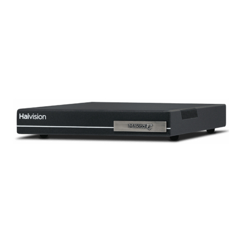
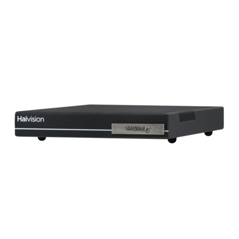
Haivision Makito XR User manual

HVS-ID-IG-MAKXR-22, Issue 01 Page 1 of 25
Makito™ XR Encoder Installation Guide
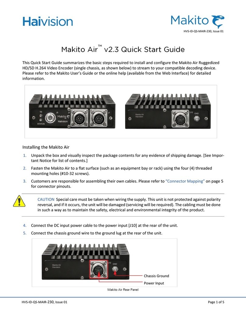
This Installation Guide summarizes the basic steps required to install and configure the Makito XR SD/HD/3G SDI
H.264 Video Encoder (single chassis, as shown below) to stream to your compatible decoding device. Please refer
to the Makito X User’s Guide or the online help (available from the Web Interface) for detailed information.
NOTE We recommend that you familiarize yourself with this Installation Guide before installing your
Makito XR.
The Makito XR is a rugged COTS encoder designed for the most
demanding Intelligence, Surveillance, and Reconnaissance (ISR)
applications and built to match the physical and mission-critical
requirements of Full Motion Video (FMV). The Makito XR High
Profile encoder supports up to four 720p60 HD (in the X4R model)
or two 1080p60 HD/3G inputs (in the X2R model), and can
simultaneously output two H.264 streams, each at different bit
rates. Scaling and frame rate settings can be adjusted on-the-fly.
Applications
Designed for integration on both manned and unmanned platforms, including aerial, naval, and
ground vehicles, the Makito XR is a single Line Replaceable Unit (LRU) that will not require major system upgrades
to existing platform designs. Tested against the highest international standards for ruggedization, including MIL-
STD 810G, MIL-STD 1275E and MIL-STD 461F, it can survive shock and vibration from any mobile application,
including law enforcement, military, and underwater vehicles deployed by oil and gas companies.
<Sbe]`Y
;OYWb]F@
623\Q]RS`
2SQ]RS`
F@

Makito XR Installation Guide
Makito XR Physical Characteristics
HVS-ID-IG-MAKXR-22, Issue 01 Page 2 of 25
Makito XR Physical Characteristics
Makito XR Power Supply Unit Characteristics
Makito XR Product Numbers
CAUTION We strongly recommend that you install the Makito XR in an enclosure for protection against
weather and other environmental stresses. The ambient temperature inside the enclosure should be
between -40°C and +71°C, and the relative humidity between 0 and 100%. If you have specific questions
regarding the suitability of the Makito XR in your operating environment, please contact Haivision Tech-
nical Support.
Dimensions 8.5” W x 3.9” H x 6.7” D
Material Aluminum 6061 T651 per SAE AMS-QQ-A-250/11
Weight 6.8 lbs. (3.08 kg)
Finish External: (Option 1) Black anodized, as per MIL-A-8625F, Type 2, Class 2; (Option 2) CARC white
Internal: Machined T651
Input Voltage 28V DC / 30W (max.) Storage Temperature -51 to 85 deg C from PDD
Input Protection Reverse polarity protection Working Temperature -40 to 71 deg C
S-292E-X2R Dual channel 3G-SDI Makito X Ruggedized with black anodized finish
S-292E-X4R Quad channel HD-SDI Makito X Ruggedized with black anodized finish
S-292E-X2R-W Dual channel 3G-SDI Makito X Ruggedized with white CARC finish
S-292E-X4R-W Quad channel HD-SDI Makito X Ruggedized with white CARC finish

Makito XR Installation Guide
Before You Begin
HVS-ID-IG-MAKXR-22, Issue 01 Page 3 of 25
Before You Begin
1. Unpack the box and visually inspect the package contents for any evidence of shipping damage. See the
Important Notice document in the box for a list of contents.
2. In addition to the contents of the Makito XR box, you may need to have the following items available:
• Four #10-32 or M5 screws for mounting
• Haivision cabling kits (see “Accessory Product Numbers” on page 5), or your own custom cables (see
“Makito XR Pinouts” on page 5)
• A laptop with web browser, Telnet client, and video player (e.g. VLC)
NOTE Connector drawings, kitting and terminated cabling drawings are available upon request.
3. In order to be able to view the output from the Makito XR, make sure you have a decoding device or video
player that is able to support the UDP Transport Stream format.
NOTE If the Makito XR is to be installed in a remote location (e.g. on a utility pole, or on a mobile plat-
form), we recommend that you follow the instructions in this Installation Guide to perform an initial set-
up in a “staging” environment, such as a lab or control center. Once the encoder has been set up and is
demonstrated to be operating normally, you can then move it to the remote location.
CAUTION Before installing the Makito XR, please refer to the section on “Safety Guidelines” in the
Makito X User’s Guide. Only connect the unit to a compatible power source. If an electrical fault occurs,
disconnect the unit and contact Haivision Technical Support. Never try to force the connections when
setting up the system as this may damage the unit.
CAUTION Hot surface. Avoid contact. The chassis can achieve a surface temperature 95°C in poorly
ventilated environments, and may cause personal injury if touched.
ATTENTION Surface chaude. Eviter le contact. Le châssis peut atteindre une température de surface de
95°C dans des environnements mal ventilés et peut causer des blessures en cas de contact.
WARNING This unit is intended for installation in restricted access areas. A restricted access area can
be accessed only through the use of a special tool, lock and key, or other means of security.
AVERTISSEMENT Ce produit est destiné à être installé dans une zone d'accès restreint. Les zones d'accès
limité sont protégées par un mécanisme spécifique, une serrure et une clé ou tout autre dispositif de sé-
curité.
NOTE While the Makito XR has a real-time clock (RTC), it has no RTC battery. In the event of a power loss,
the system date and time settings are lost. For any application with a requirement for standalone syn-
chronized system timing (or derived time codes), an NTP server should be used to provide time and date
synchronization. Refer to the Makito X User’s Guide for details.
Makito XR Installation Guide
Installing the Makito XR
HVS-ID-IG-MAKXR-22, Issue 01 Page 4 of 25
Installing the Makito XR
1. Position the appliance against a solid base.
CAUTION The surface temperature of the chassis can reach 95°C in poorly ventilated environments. We
recommend that you fasten the appliance to a metal (cold) plate to increase heat dissipation.
2. Fasten the appliance to its support base with four screws (size 10-32, or M5).
3. Fasten a grounding wire (10 AWG minimum) to the grounding lug using the nut and lock washer provided.
CAUTION The chassis must be properly grounded in order to provide protection against lightning
strikes and other power surges.
Mounting
hole
Mounting
hole
Mounting
hole
Mounting
hole
Ref: TIID-031 Rev. C-
Grounding lug with
M5 thread
Power indicator
night-vision LED
(green = power on)
Encoder status
night-vision LED
(bi-color: green or yellow)

Makito XR Installation Guide
Accessory Product Numbers
HVS-ID-IG-MAKXR-22, Issue 01 Page 5 of 25
Accessory Product Numbers
Makito XR Pinouts
The J1 to J4 connectors on the Makito XR are GLENAIR 38999 series shells. J5 is a MIL-DTL-38999 matched
impedance connector. The coaxial pins are GLENAIR 852-056-02. For detailed pinout information see “Appendix
A: Makito XR Encoder Pinouts”.
NOTE Connector drawings, kitting and terminated cabling drawings are available upon request. Contact
Haivision Technical Support
CA-292E-XR-CONNSET MIL-STD connector set (power, video, Ethernet/serial) — J1 to J5
CA-292E-XR-TERMSET Commercial break-out connectors terminated cable set (Ethernet = RJ45, serial=DB9,
4-input audio, video BNC, power) with MIL-STD connectors
P-292E-XR-PS Power supply for the XR unit — 120/240 AC to +28V DC (40 Watts) with locking
connector
J1 J2
J3
J4 J5

Makito XR Installation Guide
Connecting the Makito XR to the Network and Video Sources
HVS-ID-IG-MAKXR-22, Issue 01 Page 6 of 25
Connecting the Makito XR to the Network and Video Sources
1. Connect video, serial and network cables, referring to the images below:
2. Remove the protective caps from the Makito XR’s connectors
3. Connect the Makito XR’s J4 port to the IP network using the Ethernet cable:
4. (Optional) Connect the Makito XR’s J2 port to a metadata source or to the serial port of a computer using the
maintenance breakout cable (shown following).
Makito XR
J2 — Maintenance
connector (serial,
USB, and reset)
J1 — Power connector
LED1 — Power status
J3 — Future use
J4 — I/O connector for network commu-
nications (stream output; web interface)
J5 — Connector for video input
(including metadata)
LED2 — Video
encoder card status
RJ-45

Makito XR Installation Guide
Connecting the Makito XR to the Network and Video Sources
HVS-ID-IG-MAKXR-22, Issue 01 Page 7 of 25
NOTE The reset button provides two options:
•If you press and hold the button for less than 4 seconds the system resets and load loads the last
saved configuration. If no configuration was previously saved, the default settings prevail.
•If you press and hold the button for more than 4 seconds, the module performs a complete factory
reset. It clears all of the previously configured settings, including IP, streams and encoder
configurations.
5. Connect the Makito XR’s J5 port to your video source(s) using the video breakout cable.
NOTE The Makito XR supports up to 2 video inputs @ 1080p50/59.94/60 (in the X2R model), or up to 4
video inputs @ 1080p25/29.97/30 (in the X4R model).
6. Power up the unit. Note that there is no power switch on the Makito XR appliance. The power is
automatically on when the unit is plugged in.
CAUTION The power cord is used as the main disconnect device. Ensure that the socket-outlet is locat-
ed/installed near the equipment and is easily accessible.
ATTENTION Le cordon d'alimentation est utilisé comme interrupteur général. La prise de courant doit
être située ou installée à proximité de l'équipement et être facile d'accès.
• Insert the 3-pin connector of the power cable into the power input jack (J1) at the rear of the encoder.
Make sure the connector is properly inserted and locked to avoid intermittent power problems.
• Connect the power cable to a 28V power source (the P-292E-VR-B PSU can be used to convert from
+120V AC to +28V DC).
USB 2.0
(Future use)
DB-9
RS-232/422
System
Reset
J2
Mini-BNCJ5
J1

Makito XR Installation Guide
Connecting the Makito XR to the Network and Video Sources
HVS-ID-IG-MAKXR-22, Issue 01 Page 8 of 25
• The Status LED next to J5 will start blinking green, indicating that the encoder is booting up.
• Wait until the Status LED stays solid green, indicating that the encoder is ready for operation.
NOTE The Makito XR performs Built-in Self Tests (BIST) and Power-On Self Tests (POST) to ensure that the
hardware and firmware are operating reliably and correctly. BIST provides a minimal suite of tests that
test the various hardware and firmware sub-systems to ensure correct operation. The POST suite of tests
(a subset of the BIST suite) are performed every time there is a power-cycle. All BIST/POST configuration,
status and test results are available via CLI (serial, Telnet or SSH). For more information, please refer to
the Makito X User’s Guide.

Makito XR Installation Guide
Modifying the Makito XR’s IP Address
HVS-ID-IG-MAKXR-22, Issue 01 Page 9 of 25
Modifying the Makito XR’s IP Address
If you haven't changed the factory presets, and if not specified elsewhere in the shipment, the encoder’s IP
address is set by default to: 10.5.1.2. To be able to log in to the Makito XR Web interface, your computer has
to be in the same IP address range (subnet). You may have to temporarily change your computer’s IP address to
be in the same subnet as the encoder. Only then will you be able to access the encoder and change its IP address,
and then afterwards change your computer's IP address back.
TIP After you change the Makito XR encoder’s IP address, we recommend that you document it some-
where, and label the chassis.
1. If you have not already done so, power up the Makito XR.
2. The Makito XR comes pre-configured with the following settings:
* The IP address of your computer must be in the same subnet.
3. Open a Web browser, type the IP Address for the Makito XR into the URL address bar, and press Enter.
4. Log in to the Makito XR Web Interface, using the following default administrative username and password:
* Be sure to change the default password.
NOTE While the Web interface is most commonly used to control the Makito XR, a Command Line Inter-
face (CLI) is accessible via Telnet or SSH. For more information, please refer to the Makito X User’s Guide.
IP Address* Subnet Mask Gateway
10.5.1.2 255.255.0.0 10.5.0.1
Admin Username Password*
admin manager

Makito XR Installation Guide
Modifying the Makito XR’s IP Address
HVS-ID-IG-MAKXR-22, Issue 01 Page 10 of 25
5. Select the ADMINISTRATION icon from the toolbar, and then select NETWORK (under SETTINGS).
6. Type in the new IP address. If required, select or enter other new value(s) in the appropriate field(s).
7. To apply your changes, click Apply, and then click Reboot. (You must reboot the system for the changes to
take effect.)
NOTE Remember to change your computer network settings to be on the same network segment as the
Makito XR.

Makito XR Installation Guide
Setting up a Test Stream
HVS-ID-IG-MAKXR-22, Issue 01 Page 11 of 25
Setting up a Test Stream
Setting up a test stream requires that you have an active video source connected to the Makito XR. You will need
to configure an encoding instance based on your video source, and then configure an output stream for that
encoder. For detailed information, please refer to Chapter 4 of the Makito X User’s Guide.
1. If you have not already done so, power up the Makito XR.
2. Open a Web browser, type the IP Address* for the Makito XR into the URL address bar, and press Enter.
* The IP address of your computer must be in the same subnet (see “Modifying the Makito XR’s IP Address”
on page 9).
3. Click the STREAMING icon on the toolbar, and then click VIDEO ENCODERS from the sidebar menu.
The Video Encoders List View opens, as shown in the following example.
4. From the Video Encoders List View, click a link in the table to select the encoder.
Click link to o
p
en Detail View

Makito XR Installation Guide
Setting up a Test Stream
HVS-ID-IG-MAKXR-22, Issue 01 Page 12 of 25
The Video Encoder Detail View opens, displaying the settings for the selected video encoder (see following
example).
5. Select or enter the new value(s) in the appropriate field(s).
6. Click Start, and then click Apply.
7. Click the STREAMING icon on the toolbar, and then click OUTPUTS from the sidebar menu.
The Output Streams List View opens, as shown in the following example.

Makito XR Installation Guide
Setting up a Test Stream
HVS-ID-IG-MAKXR-22, Issue 01 Page 13 of 25
8. To add an output stream, click Add.
The Output Streams Detail View opens (as shown in the following example for a new stream).
9. Type a Name for the stream and select TS over UDP for the Protocol.
10. In the Source section, select the encoder you started in step 6. from the Video menu.
11. In the Destination section, type in a valid multicast Address (e.g. 239.192.2.3) and Port number (e.g.
2000).
NOTE The Multicast address range is from 224.0.0.0 to 239.255.255.255. Multicast addresses from
224.0.0.0 to 224.0.0.255 are reserved for multicast maintenance protocols and should not be used
by streaming sessions. We recommend that you use a multicast address from the Organization-Local
scope (239.192.0.0/14).

Makito XR Installation Guide
Viewing the Test Stream
HVS-ID-IG-MAKXR-22, Issue 01 Page 14 of 25
12. To add metadata to the stream, select the Metadata source, and (optionally) select the encapsulation type
(Data Carriage).
13. To apply your changes and start streaming, click Apply.
The changes will take effect immediately but will be lost after a reboot. For information on saving configura-
tion settings, please refer to the “Saving and Loading Presets” section of the Makito X User’s Guide.
Viewing the Test Stream
1. Make sure your decoding device (or software) is compatible with the UDP Transport Stream format.
2. Turn the device on and connect it to a display (if applicable), or open your video player software (e.g. VLC).
3. Make sure you are on the same network segment as the Makito XR, and
4. Tune your decoding device or software to the multicast address of the test stream coming from the Makito
XR.

Makito XR Installation Guide
Abbreviations & Definitions
HVS-ID-IG-MAKXR-22, Issue 01 Page 15 of 25
Appendix A: Makito XR Encoder Pinouts
This appendix contains the pinout descriptions for the Makito XR SD/HD/3G SDI H.264 Video Encoder. This
information must be used in conjunction with Haivision drawing no. TIID-031 (Makito XR Enclosure External Cable
Connections).
Abbreviations & Definitions
References
For additional information, please refer to the following documents:
• Makito XR External Cable Connections (TIID-034)
• Makito XR Data Sheet
• Makito X User’s Guide
• SMPTE 259M (SD-SDI), 292M (HD-SDI) and 424M (3G-SDI)
• IEEE 802.3-2012 (Ethernet)
• USB standard, USB Implementers Forum (USB.org)
• High Definition Audio (HDA) codec specification (Rev.1.0a), Intel
EMC Electromagnetic Compatibility
ESD Electro Static Discharge
GBE Gigabit Ethernet per IEEE 802.3ab (same as 1000BASE-T)
GPIO General Purpose Input/Output
HDA High Definition Audio (Intel standard)
I2C Two-wire Serial Interface
NC No Connect
PCB Printed Circuit Board
p/n Part Number
SCD Source Controlled Drawing / Source Controlled Document
SDI Serial Data Interface (governed by SMPTE standards)
SKU Stock Keeping Unit
TBD To be determined
USB Universal Serial Bus

Makito XR Installation Guide
Enclosure Front Panel
HVS-ID-IG-MAKXR-22, Issue 01 Page 16 of 25
Enclosure Front Panel
The Makito XR video encoder enclosure offers total of 5 MIL-STD connectors for external cables attachment.
Makito XR Video Encoder Enclosure Front View
Connector Part Numbers
J1 to J4 are GLENAIR 38999 series shells.
J5 is a MIL-DTL-38999 matched impedance connector that accommodates 4 pin contacts, size 8, with 75-ohm
impedance. The coaxial pins are GLENAIR 852-056-02
Refer to Haivision drawings TIID-031 and TIID-034 for detailed list of part numbers.
List of Connectors
ID Description Number of Contacts
J1 Power Connector 3
J2 Maintenance Connector 26
J3 Future use 85
J4 Ethernet 85
J5 Video Input Connector 4 pins (coaxial, 75-ohm)
List of LED Indicators
ID Description Location
LED1 Power Status Near J1
LED2 Video Encoder Card Status Near J5

Makito XR Installation Guide
Power Entry Connector (J1)
HVS-ID-IG-MAKXR-22, Issue 01 Page 17 of 25
Power Entry Connector (J1)
Refer to the Makito XR video encoder data sheet for power requirements details.
J1 Power Connector Pin Locations
Power Connector J1
Manufacturer GLENAIR
Connector Type MIL-DTL-38999
Part Number 805-004-07ZNU8-23PA
Front Connector Power Location
Connector Pin Description
J1 1 28 Volt Input – 1.0A max
J1 2 28 Volt Return
J1 3 Chassis Ground

Makito XR Installation Guide
Maintenance Connector (J2)
HVS-ID-IG-MAKXR-22, Issue 01 Page 18 of 25
Maintenance Connector (J2)
USB 2.0 Interface
The Makito XR video encoder has a USB 2.0 Host Interface which is provisioned for future use applications. It is
currently disabled.
Do not attach a USB device requiring more than 500 mA.
I/O Connector: J2
Manufacturer GLENAIR
Connector Type MIL-DTL-38999
Part Number 805-005-07 ZNU 12-26SA
Feature Reference
USB 2.0 interface Refer to “USB 2.0 Interface”
RS-232 serial interface Refer to “RS-232 Serial Interface”
Reset Button Refer to “Reset Button”
Front Connector View I/O Location
Connector Pin Description
J2 11 USB7_GND signal
14 USB7 Drain Wire – Cable shield SH - Shield
15 USB7 5V - Always enabled 500 mA Max
18 USB7_D+ Data signal ESD Protected ± 8 kV
23 USB7_D- Data signal ESD Protected ± 8 kV
All Others Not Connected (NC)

Makito XR Installation Guide
RS-232 Serial Interface
HVS-ID-IG-MAKXR-22, Issue 01 Page 19 of 25
J2 Maintenance Connector USB Pin Locations
RS-232 Serial Interface
Makito XR video encoder can be managed through a RS-232 serial interface, one commonly used for configuration
making use of the Command Line Interface (CLI). This port is designated as COM1.
Front Connector View I/O Location
Connector Pin Description
J2 1 COM1 – Drain Wire / Cable Shield SH
3 COM1 – RX RS-232 Receive Data
signal
RX1 ESD Protected ± 18 kV
6 COM1 – TX RS-232 Transmit Data
signal
TX1 ESD Protected ± 18 kV
8 COM1 – RS-232 Ground signal

Makito XR Installation Guide
Reset Button
HVS-ID-IG-MAKXR-22, Issue 01 Page 20 of 25
J2 Maintenance Connector COM1 – Module RS-232 Pin Locations
Reset Button
A reset button (RST# signal) can be asserted to ground to provide the user with 2 options.
• If RST is asserted for 0s < t < 4s duration, the system resets and loads the last saved configuration. If no
configuration was previously saved, the default settings prevail.
• For assertion of t > 4s, the module performs a complete factory reset. It clears all of the previously configured
settings, including IP, streams and encoder configuration.
Front Connector I/O Location
Connector Pin Description
J2 19 System Reset Ground
24 System Reset Signal – asserted LOW RST# 3.3V Input
ESD Protected ± 18 kV
Table of contents
Other Haivision Media Converter manuals

Haivision
Haivision Makito XH User manual

Haivision
Haivision Kraken CR User manual

Haivision
Haivision Makito XH User manual

Haivision
Haivision Makito User manual

Haivision
Haivision Makito X User manual

Haivision
Haivision S/B-292E-DVI User manual

Haivision
Haivision Kraken User manual

Haivision
Haivision Makito User manual

Haivision
Haivision Makito HVS-ID-QS-MAKD-130 User manual

Haivision
Haivision Makito Air v2.3 User manual