Haldex EB Plus Manual

OPERATOR'S
GUIDE
000 700 241 / 02.05. / Redditch

2
The demand pressure is then
modified using data from the air
suspension (Electronic Load
Sensing), and may be further
modified when a wheel speed
sensor detects imminent locking
of the sensed wheels (ABS) .
The output to the brakes is
exercised by the ECU control of
the EPRV's see Fig 2.
TheEB+ECUalsoprovidesupto
5 auxillary functions such as
automaticreset-to-rideheight
(COLAS ), lift axle control
(ILAS -E),retarder and Stability
controlduringABS
EB+incorporatesanodometer
facility which measures total
distance of the trailer and its
read-outisshownonaoptional
EB+INFO CENTRE unit.
TheEB+INFO CENTRE is a side of
trailermountedunitusedalsofor
read-outofdiagnosticcodesand
otherinformationasavailablefrom
theEB+ECU.
TheEB+also incoporatesa
enhancedinformation storageand
retrievalfacility.
Forthefleetoperator,a 'Fleet Log
Reader'allowsthe compilation of a
full history of each trailer or long
termmonitoring.
Forthetrailer manufacturer,an
'End-of-line'Testing(EOLT)to
confirmcorrect performance ofthe
EB+system.
For semi and centre axle,
Air suspension trailers:-
EB+ (1M and 2M) features
♦Brake application control for all
trailer wheels
♦ABS - 2S/1M or 2S or 4S/2M
2 or 4 Sensors and 1 or 2
Modulators (EPRV's)
♦PneumaticLoadsensingfunction
♦CANinterface
♦'End-of-Line'Test
♦FleetLogReader
♦Odometerfunction
♦Reset-to-RideHeight(COLAS® )
♦LiftAxle (ILAS® -E)
♦Steer axle lock
♦EB+ Stability (2m only)
♦LiningWearIndication
For Full Trailers :-
EB+ 3M (2M +1M)
A 4S/3M system with
featuresas above.
Your trailer has been fitted with the
latest technologyHaldex Electronic
Braking System EB+.This system
has been specifically designed to be
effective,reliableand easy to service.
The purpose of this booklet is to
describethe componentsinvolvedand
giveyousufficient information to make
your use of the system easy.
The use of the diagnostic system is
describedbut when overhaulofthe
componentsisrequired, we advise
you to referto the full SERVICE
MANUAL whichdescribes
replacementprocedures fully.
SystemDescription Page2
SystemLayout Page4
SystemDiagnostics Page6
Warningdeviceand Page7
SystemCheck
Procedure
DiagnosticSystem Page9
Codes
ECUConnection Page12
Identification
WiringDiagram
Semi,CentreaxleTrailers Page13
FullTrailers Page14
PipingDiagram
Semi,CentreaxleTrailers Page15
FullTrailers Page 18
Multimeterreadings Page 19
Recommended Page 20
Maintenance
Schedules
ServiceParts Page 21
GeneralInformation Page 24
UserNotes Page 25
The position of the various
components is shown in Tri-axle
layout, Fig 1. The system is equally
compatible with single and tandem
axles.The EB+systemfeaturesare,
amodularintegrated construction,
anencapsulatedElectronic Control
unit(ECU)andElectro pneumatic
relayvalve/s(EPRV's),over-moulded
connectors,integratedpressure
transducers and a flash up-gradable
program memory.
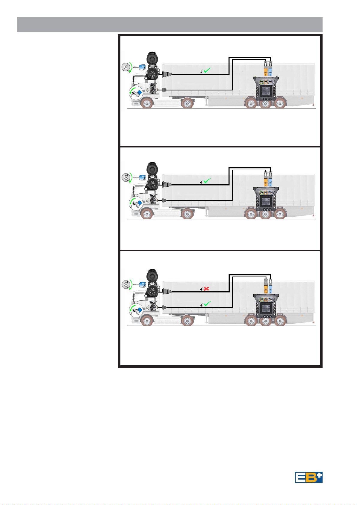
Onset of braking is denoted by
either the presence of a demand on
the ISO11992 data link (CAN) via
the ISO7638 connector and/or by
the operation of the pressure switch
in the pneumatic control line.
Driver demand pressure is then
determined electronically either by
the data link or control line pressure
transducer within the EPRV's
assembly.
EB+=A nt i lock Brake System
+ Electronic Load Sensing
+ CAN (Controller area network
ISO11992 data link-
computer data from and to
the towing vehicle)
The system reacts to electrical or
pneumatic signal from the towing
vehicle. It electronically processes
those signals plus signals received
from other sensors on the trailer.
In response to those signals the
EB+
regulatespressureto the brake
chambers.
Operators Guide
Concept
System Description
®
®
Contents

Fig 1
3
General Components Guide
Driver's information
plate EB+INFOCENTRE
ISO 7638 - 7 Pin
Connector assembly
Sensor and Exciter
Relay
Emergency
Valve
Pressure
Switch
EB+ECUand
EPRV's assembly
Fig 2
ISO 7638/CAN
Control line REV Pressureswitch Sensor
Air suspension EB+
1M
2M
Option
Ref Page22
InstallationsOption
Example Semi / Centre axle Trailers

4
The system fitted to your Semi-trailer
may have 2 or 4 Sensors and 1 or
2Modulators(EPRV's). The variants
availablebeing2S/1M, 2S/2M and
4S/2M.
ForFull-Trailers(alsospecial semi-
trailers) the system available is 4S/3M
(2M Master ECU assembly and a
1MSlaveECUassembly).
The layout of the chassis components
are shown in Fig 6. The ECU and
EPRV'sareintegratedtogether for
ease of installation and maintenance.
The powering of the system is via :
ISO 7638- 7 Pin - Full EBS function
Fig 3.
The EB+system can also be
powered via :
ISO 7638- 5 Pin - No CAN data bus
ABS + ELS function only Fig 4.
As an safety back-up
ISO 1185 (24N) - Stop Light
powering providesABSfunction only
(1M and 2M systems only)
Fig 5.
The ISO 7638 controls a Trailer
warning device in the driver's
console .
The warning device has two
functions:
-To indicate system integrity via the
correct sequence (see Fig 8,
on page 7 and step 1- Fig 9 on page
8) every time the EB+ECU is
electrically powered up.
-To indicate by a permanent display,
when the vehicle is moving, if a fault
has been detected.
System Layout
ISO 7638- 7 Pin
EBS
= ABS + ELS function only
No CAN data bus
ISO 7638- 5 Pin
ABS
= Full EBS function
ISO 1185- (24N)
ABS/EBS
= On foot brake application
ABS function ONLY
Fig 3
Fig 4
Fig 5
EB+
EB+
EB+

5
Chassis Components
Fig 6
Item Description
1EB+Label
2 ISO 7638 - 7 Pin Socket assembly
3 Safetyback-upcable ISO 1185 (24N)
4 RelayEmegency Valve
5 Pressure switch assembly
6EB+INFOCENTRE
7 Diagnostic Side of Vehicle cable assy
8 Sensorassembly
9 Exciter
10 EB+ECU and Modulatorsassembly
11 Auxiliary1 (COLAS®)
12 Auxiliary 2 (ILAS® - E)
13 Auxiliary 4 Lining Wear Sensing
14 Auxiliary5LateralAccelerometer
ISO 7638
ISO 1185
(24N)
1
24
10
11
8
9
9
10
3
5
12
13
14
6
Option Ref Page22
7

Fig 7
ALTERNATIVE - Directly Connected to ECU or
Side of Vehicle connection
Diagnostic
connection
'DIAGN'
on ECU
ALTERNATIVE POSITIONS
Animportantfeatureof the
EB+system is that it provides
an extensive on board diagnostic
capability. The system displays a
range of codes, which allow rapid
diagnosis of the problem should
one occur.
Diagnostic communication is in
accordance to ISO 11898 using
Keyword (KWP2000) protocol
and is accessed by the
ISO 7638 - 7 pin connector which
uses pin 6 and 7 as a CAN data
bus. Any suitable device connected
to this CAN data bus may read
diagnostic information.
6
PCINTERFACE
System Diagnostics
AHaldexPC based program
DIAG+may be used for more
advanceddiagnosis. This also
allowsconfigurationwithsystem
parameterstobe entered and an
End-of-LineTest to be carried out.
An EB+INFO CENTRE can be
connectedpermanentlytothe ECU's
diagnostic 'DIAG'connection.While
theECUispoweredinformation is
transferredto the InfoCentre's
memory,whichcanberecalled.Power
issuppliedfrom the vehicle system via
theECUdiagnosticsconnector.
TheEB+INFOCENTREprovides a
multi-digit display of:
EB+INFOCENTRE
Changes:
Servicedistance
Serviceinterval
Wheel scale factor
Clock(timeand date)
Options-on/off(parameter updating/
backlight)
Password(PIN number)
UnlockInfo Centre(PINnumber
Un-known)
Testing:
Load
Wheels (sensor / cabling check)
Pressure
Plate(Loadplate data)
Auxiliaries
BrakeTest
LiningWear Indication
Information:
ReadDiagnosticTroubleCode (DTC)
ClearDTC
Configuration
ECUsoftwareversionnumber
ECUserial number
Vehicle IdentNumber(VIN)
ManufacturerOEM
InfoCentresoftwareversionnumber
Distance:
Odometer-Totaldistance
Tripdistance(1stand 2nd)
Servicedistance
Wheel scale factor
Clock(timeand date)
ClearTrip1 and 2
Connect
toECU
directly
orviaaSide
ofVehicle
connector

7
A warning device located on
the driver's console of the towing
vehicle is operated from the
ISO 7638 power cable only when
the EB+is powered by the ignition
switch. Fig 8.
Warning Device
The warning device function
depends on the ISO 7638
power supply used:
Note: If a dedicated power source
is unavailable to the EB+from the
ISO7638 connector then system
integrity will not be indicated by
thecab mounted warningdevice.
As an option to the cab warning
device a trailer mounted warning
lamp may be provided as an
auxiliary function. This lamp
mimics the signal to the cab
warning device but will only
function if the ISO7638 power
is connected.
Note: The signal produced may
be different to that produced by
the cab device due to possible
modification of the cab device
by the towing vehicle.
System Check Procedure
1. On power up of the system, the warning
device must indicate in the following
sequence in order to show a fault-free
system:
OPTION 'A' - Industry normal
2. During the self-check
procedure, the system cycles
the EPRV's. With foot brake
applied one exhaust of air
from each EPRV will be
audible.
Once these two checks are
made with correct results, no
furtherchecksare required.
If the results are not satisfactory,
HaldexDIAG+or EB+Info Centre
should be used to establish the
diagnosis.
This information is described
visually in Fig 9 on page 8.
Fig 8
Warning
device
WarningDevice,SystemCheck Procedureand Power Up Modes
ON for 2 seconds = Warning device
OK and
system self-
checking.
OFF for 2 seconds= System
self-checked
and preparing
to check
sensors.
ON until moving = System
waiting for
vehicle to
move above
10 km/h in
order to check
that the
sensorsare
working.
OFF = Once the
vehicle is
moving above
10 km/h and
the warning
device clears,
the electronic
system is fully
checked.
Power Up Modes
The EB+system has two power
up modes. With switching the
Ignition on (B+ applied) the
following occurs:
With No yellow line pneumatic
pressure (i.e. Brakes OFF)
The system adopts load sensing
mode when the brakes are
applied. This load sensing mode
is limited to 2 minutes for any
single brake application, after
which it returns to a
push-through condition
(approx 1:1).
The push-through condition is
cancelled on vehicle movement
above 10 km/h returning the
system to load sensing
operation.
With yellow line pneumatic
pressure (i.e. Brakes ON)
(Park on air)
Apply foot brake, switch
Ignition On.
The system adopts a
push-through (approx 1:1)
condition. When the brakes are
released and re-applied the
system remains in push-through
unless the brakes are released
for longer than 2 minutes, after
which it returns to load sensing
operation.
This condition is cancelled on
vehicle movement above
10 km/h returning the system
to load sensing operation.
ON
OFF
2 sec. 2 sec. @
10 km/h
OPTION 'B' - Haldex normal
ON for 2 seconds = Warningdevice
OKand
system self-
checking.
OFF = System
self-checked
(notsensors)
ON
OFF
2 sec.

8
STEP
2
STEP
3
Power up, Apply foot brake :
STEP 1WATCH WARNING DEVICE IN TOWING VEHICLE
STEP 2Listen for EPRV CYCLE.
STEP 3Remove foot brake
SPIN EACH SENSED WHEEL IN TURN,
Refer to diagnostic code listing.
STEP
1
Example :
4MULTIPLE LAMP SEQUENCE
TheHaldexEB+incorporates a
modified lamp flash of three flashes.
The red lamp will flash when the
system is powered up when at rest.
This lamp sequence relates to :-
1. Service due - indicates that
trailer or system service distance is
due. After servicing the trailer or
system the next service distance
must be reset by using the
Info Centre or EOLT program.
2. NON EB+fault -Afault
with a device connected to the
EB+but not directly effecting the
EB+,for example:Reset-to-Ride valve
(COLAS®).
Fig 9
READING
DIAGNOSTIC
CODES USING
DIAGNOSTIC
CODE
Refer to Diagnostic
Trouble Code listing
Pages9-11
EBS EBS
EBS
Key
EPRV
Cycle
O.K.
NOT O.K.
Test Procedure - Summary
EBS
Option 'A' Option 'B'
ODOMETER
AND LOAD
DISPLAY
ALL SEGMENT
DISPLAY TEST INFORMATION
MENU DISPLAY
DIAGNOSTIC
MENU
DISPLAY
EB+Info Centre
'EB+ INFO'
DISPLAY
22
12
21

DTCDISPLAYED
ECUTIME OUT No supply on ignition switched line.
or Possiblecauses:
NOLINK Truck fuse blown.
EB+INFOCENTRE or cable fault.
Open circuit B -. ISO7638 not connected
SENSOR GROUP
If a Diagnostic Trouble Code not listed below is displayed check for intermittent sensor and wiring faults.
9
Diagnostic Trouble Codes (DTC))
))
)
S1A CONT 1A Sensor/wiring open or short circuit
S1B CONT 1B Sensor/wiring open or short circuit
S2A CONT 2A Sensor/wiring open or short circuit
S2B CONT 2B Sensor/wiring open or short circuit
INTERMITTENT LOW SENSOR OUTPUT GROUP
S1A SIGNAL 1A Sensor signal fault
S1B SIGNAL 1B Sensor signal fault
S2A SIGNAL 2A Sensor signal fault
S2B SIGNAL 2B Sensor signal fault
Possible causes:
Loose sensor, connection, bracket or exciter. Damaged exciter.
Maladjusted sensor or worn sensor cable insulation.
LOW SENSOR OUTPUT GROUP
S1A OUTPUT 1A Sensor system fault
S1B OUTPUT 1B Sensor system fault
S2A OUTPUT 2A Sensor system fault
S2B OUTPUT 2B Sensor system fault
Possible causes:
Sensor worn, maladjusted sensor, wiring open or short circuit
BRAKE APPLY SOLENOID GROUP
BRK APPLY SC Brake apply solenoid short circuit
BRK APPLY OC Brake apply solenoid open circuit
BRK APPLY SC DRIVE Brake apply solenoid short circuit permanently energised
BRK APPLY UNSPEC Brake apply solenoid control circuit fault
EPRV 21 HOLD AND DUMP SOLENOID GROUP
EPRV 21 HOLD SC Modulator 21 hold solenoid short circuit
EPRV 21 DUMP SC Modulator 21 dump solenoid short circuit
EPRV 21 HOLD OC Modulator 21 hold solenoid open circuit
EPRV 21 DUMP OC Modulator 21 dump solenoid open circuit
EPRV 21 HOLD SC DRIVE Modulator 21 hold solenoid short circuit permanently energised
EPRV 21 DUMP SC DRIVE Modulator 21 dump solenoid short circuit permanently energised
EPRV 21 HOLD UNSPEC Modulator 21 hold solenoid control circuit fault
EPRV 21 DUMP UNSPEC Modulator 21 dump solenoid control circuit fault

DTCDISPLAYED
EPRV 22 HOLD AND DUMP SOLENOID GROUP
EPRV 22 HOLD SC Modulator 22 hold solenoid short circuit
EPRV 22 DUMP SC Modulator 22 dump solenoid short circuit
EPRV 22 HOLD OC Modulator 22 hold solenoid open circuit
EPRV 22 DUMP OC Modulator 22 dump solenoid open circuit
EPRV 22 HOLD SC DRIVE Modulator22hold solenoid short circuit permanently energised
EPRV 22 DUMP SC DRIVE Modulator22dumpsolenoidshort circuit permanently energised
EPRV 22 HOLD UNSPEC Modulator 22 hold solenoid control circuit fault
EPRV 22 DUMP UNSPEC Modulator 22 dump solenoid control circuit fault
DEMAND PRESSURE TRANSDUCER GROUP
DEMAND SC Service line pressure transducer short circuit
DEMAND OC Service line pressure transducer open circuit
DELIVERY PRESSURE TRANSDUCER GROUP
EPRV 21 DEL SC Modulator 21 delivery pressure transducer short circuit
EPRV 21 DEL OC Modulator 21 delivery pressure transducer open circuit
EPRV 22 DEL SC Modulator 22 delivery pressure transducer short circuit
EPRV 22 DEL OC Modulator 22 delivery pressure transducer open circuit
ONE WHEEL WITH SLOW RECOVERY GROUP
EPRV 21 SLOW REC Slow recovery of one wheel of modulator 21
EPRV 22 SLOW REC Slow recovery of one wheel of modulator 22
Possible causes:
Slow brake release, foundation brake mechanical faults, dry
bearings, broken spring, restricted piping
Check for kinks and blockages etc. Incorrect piping, Wiring.
Modulator fault. Sensor wiring crossed across an axle.
RESERVOIR PRESSURE TRANSDUCER GROUP
RESR SC Reservoir pressure transducer short circuit
RESR OC Reservoir pressure transducer open circuit
SUSPENSION PRESSURE TRANSDUCER GROUP
SUSP SC Suspension pressure transducer short circuit
SUSP OC Suspension pressure transducer open circuit
SUSP LOW Suspension pressure values outside operating range
PRESSURESWITCH GROUP
REV SWITCH SC Relayemergencyvalvepressure switch short circuit
REV SWITCH OC Relayemergencyvalve pressure switch opencircuit
REVSWITCH PNEUMATIC Relayemergencyvalvepressure switch pneumaticfault
REV SWITCH SIGNAL Relayemergencyvalve pressure switchfailedtoactivate
10
Diagnostic Trouble Codes (DTC)

DTCDISPLAYED
ISO11992 (CAN) ELECTRICAL SIGNAL GROUP
PNEUMATIC DEMAND LOSS No corresponding pneumatic demand pressure
TOWED CAN DEMAND LOSS CAN line (pin 6 and 7 on ISO7638) fault
TOWEDCAN CONTROL LOSS CAN line (pin 6 and 7 on ISO7638) data fault
SUPPLY VOLTAGE GROUP
PWR ISO7638 FAIL Power loss on pin 1 or 2 (ISO7638)
PWR LO VOLT Supply voltage at ECU less than 19v when brake apply
solenoid energised
PWR HI VOLT Supply voltage at the ECU greater than 32v
PWR UNSPEC Internal ECU fault
ECU GROUP
ECU EEERR Internal ECU fault or ECU not programmed
ECU PARAMERR Internal ECU fault or ECU not programmed
ECU EE UNSPEC Internal ECU fault or ECU not programmed
AUXILIARY COMPONENTS GROUP
AUX1 Auxiliary 1 system/wiring open or short circuit
AUX2 Auxilliary 2 system/wiring open or short circuit
AUX3 Auxilliary 3 system/wiring open or short circuit
AUX4 Auxilliary 4 system/wiring open or short circuit
AUX5 Auxilliary 5 system/wiring open or short circuit
LINING WEAR GROUP
BRAKEPADS Lining wear wiring open circuit
LATERALACCELEROMETER
LATACC OC Lateral accelerometer wiring open circuit
LATACC SC Lateral accelerometer wiring short circuit
LATACC SIGNAL Lateral accelerometer signal fault
SLAVE VALVE GROUP
SLAVEVALVESENSOR Pressure transducers open or short circuit
SLAVEVALVE MODULATOR Hold, Dump or Brake Apply solenoid open or short circuit
SLAVEVALVE CABLE Link cable open or short circuit
SLAVE VALVE SLOW REC Slow recovery of one wheel of slave valve
SLAVE SUSP LOW Suspension pressure values outside operating range
11
Diagnostic Trouble Codes (DTC)

12
Fig 10
ISO 7638
ISO 1185
(24N)
Green
Orange
Blue
Pressure
switch -
Option
Ref Page 22
SENSOR 1A
SENSOR 2A SENSOR 2B
SENSOR 1B
Blanking plugs
Blue Blue
Black
ECU Connector Identification
EB+
INFO
CENTRE
or
PC
Interface
Auxiliaryconnectors
Blanking
plug
OPTIONS
Tacho
COLAS®
Retarder
Trailerlamp
ILAS®-Efront
ILAS®-Erear
Auxpower
Steer axle lock
LiningWearLamp
Overloadlamp
Auxiliary
connectorAUX 1
Black
Blue
OPTIONS (AUX 5)
EB+ Stability (2M Semi -Retrofit)
OPTIONS (AUX 4)
Lining Wear System
OPTIONS (AUX 2 & 3)
Tacho COLAS®
Trailer lamp Retarder
ILAS®-Efront ILAS®-E rear
Auxpower Steer axle lock
System - 3M (Full Trailers)
Red
Red
SlaveECU(1M) MasterECU(2M)
ISO
7638
Blue
3M LINK POWER 'B'
BSensors
BSensors
A Sensors
ASensors
Liningwear lamp
Overloadlamp ILAS®-EFrontManual
ILAS®-ERear Manual
Blanking
plug

13
Fig 11
Key
W - White
BK - Black
BU - Blue
BN - Brown
GN - Green
RD - Red
YE - Yellow
Sensor
ISO 7638
ISO 1185
(24N)
RD
CAB LAMP
B-IGN
B+P
RD
WB+
B-
EB+INFO
CENTRE
YE W
1A
1B
EB+ECU
AUX2
AUX3
AUX4
AUX5
PSW
S2B
S1B
POWERA
POWER B
AUX1
S1A
S2A
REV
COLAS
Sensor
1
2
3
45
6
7BK
BN
W/BN
W/GN
1
4
B+IGN
B-
CAN -L
CAN -H
B-
CAN -H CAN -L
B+DIAG
BKBN
BK
BN
DIAGN
RD GN YE BU
Sensor
2B
BK
BN
BK
BN
2A
Sensor
System - 4S/2M
ISO7638
ISO1185 (24N)
EB+INFOCENTRE
REV(PressureSwitch)
COLAS®
ILAS®-E
Pressure
Switch
Option
Ref Page 22
RD
BK YE
YE
RD BK B-
OPEN CLOSED
-+
®
42
Wiring Diagram - Semi , Centre axle Trailers
1m MAX.
ILAS -E
®-
+
RD YE
PCINTERFACE
BK

14
Fig 12
Wiring Diagram - Full Trailers
Sensor
ISO 7638
CABLAMP
B-IGN
B+P
EB+INFO CENTRE
1A
1B
EB+MasterECU
AUX2
AUX3
AUX4
AUX5
PSW
S2B
S1B
POWERA
POWER B
AUX1
S1A
S2A
REV
Sensor
B+IGN
B-
CAN -L
CAN-H
B-
CAN-H
CAN -L
B+DIAG
BK
BN
BK
BN
DIAGN
RD
GN
YE
BU
Sensor
BK
BN
BK
BN
2A
Sensor
System - 4S/3M
ISO7638
3M LINK - POWER 'B'
EB+INFOCENTRE
REV(PressureSwitch)
YE
RD BK B-
OPEN CLOSED
PCINTERFACE
2B
EB+Slave ECU
AUX2
AUX3
AUX4
AUX5
PSW
S2B
S1B
POWERA
POWER B
AUX1
S1A
S2A
DIAGN
Key
W - White
BK - Black
BU - Blue
BN - Brown
GN - Green
RD - Red
YE - Yellow
YE BN
W/BN
RD
W
BK W/GN
Slave Valve Return
Dumpsol
Hold sol Pressure signal
Apply sol
5v
Signal 0v
RD
YE W
1
23
45
6
7
BN
W/BN
W/GN
BK
Pressure
Switch
Option
Ref Page 22

4
15
Fig 13
Piping Diagram - Semi , Centre axle Trailers
21
1
11
3
22
4
22
2
1
11 11
12 12
11 11
12
11
12
2
2
12
2
21
1
Emergency
Item Description
1 EmergencyCoupling
2 ServiceCoupling
3 PipeFilter
4 CombinedPark andShuntvalve
5 PressureSwitch
6 AirReservoir
7 Drainvalve
8 Test point
9EB+Assembly
10 SpringBrakeChamber
11 SingleDiaphgramBrakeChamber
12 DoubleCheckValve
13 Quick ReleaseValve
14 Test point simulator
Service
1
3
23
8
7
68
8
11 10 10
11 10
12
13
41
2
3 axle Semi-Trailer - 2 line air brake system - Spring Brake Chambers
Suspension
System
8
2
2S/1M - Side by Side Configuration - Without REV
41
14 9
5
InstallationOptionRef Page 22

16
Piping Diagram - Semi , Centre axle Trailers
4
Fig 14
21
1
11
3
22
4
22
2
1
11 11
12 12
11 11
12
11
12
2
2
4
2-1 12
12
2
21
1
Emergency
Item Description
1 EmergencyCoupling
2 ServiceCoupling
3 PipeFilter
4 CombinedPark andShuntvalve
5 RelayEmergency Valve
6 AirReservoir
7 Drainvalve
8 Test point
9EB+Assembly
10 SpringBrakeChamber
11 SingleDiaphgramBrakeChamber
12 DoubleCheckValve
13 Quick ReleaseValve
14 Test point simulator
Service
1
3
235
8
7
68
8
11 10 10
11 10
12
13
22
1
21
22
22 9
3 axle Semi-Trailer - 2 line air brake system
Suspension
System
8
21
21
4S/2M - Side by Side Configuration - With REV
41
14

17
Piping Diagram - Semi , Centre axle Trailers
4
Fig 15
23
4
21
4
22
2
1
11 11
12 12
11 11
12
11
12
2
2
12
2
21
1
Emergency
Item Description
1 EmergencyCoupling
2 ServiceCoupling
3 PipeFilter
4 TrailerControlModule(TCM)
5 AirReservoir -Service
6 AirReservoir - Suspension
7 Drainvalve
8 Test point
9EB+Assembly
10 SpringBrakeChamber
11 SingleDiaphgramBrakeChamber
12 DoubleCheckValve
13 Quick ReleaseValve
14 Test point simulator
Service
1
3
23
8
7
58
8
11 10 10
11 10
12
13
22
1
21
22
22 9
3 axle Semi-Trailer - 2 line air brake system
Suspension
System
8
21
21
4S/2M - Side by Side Configuration - With Trailer Control Module (TCM)
41
14
8
7
6
22
1
1-2
3
Suspension
System

18
Fig 16
Piping Diagram - Full Trailers
4
2
1
11 12
11
11 12
2
4
2
12
2
2
1
1
Service
1
3
2
8
7
6
8
8
14 13
14 13
15
16
22
1
22
11
8
Suspension
System
Side by Side Configuration
2 axle Full Trailer - 2 line air brake system - Spring Brake chambers
Emergency
41
17 21
3
Suspension
System
17
41
2
2-1
5
2
12
9
2
1
12 42
1
SLAVE MASTER
4
2
2
1
12
V
ST
S
10
ITEM DESCRIPTION
1 Emergencycoupling
2 Servicecoupling
3 Pipefilter
4 Shuntvalve
5 RelayEmergency Valve
6 Airreservoir
7 Drainvalve
8 Testpoint
9 Parkvalve
10 Releasevalve(Maneuveringvalve)
11 EB+ Assembly 2M(MasterECU)
12 EB+ Assembly1M (Slave ECU)
13 SpringBrake chamber
14 Single DiaphgramBrakechamber
15 Double checkvalve
16 Quick releasevalve
17 Testpointsimulator

19
B
A
Fig 17 - SensorConnector
Fig 19 - COLAS® Solenoid Connector
17
17
19
CHECKING MEASURE CORRECT REMARKS Fig
POSITION BETWEEN VALUE
Sensor output A B 0.2V AC Min. Sensor 1A, 1Bor 2A, 2B
Sensordisconnectedfrom ECU.
Wheel rotated at 1 rev/2 sec.
Sensor resistance A B >1.0 <2.4 kohm Sensor 1A, 1Bor 2A, 2B
Sensordisconnectedfrom ECU.
Earth continuity ECU/EPRV 0ohms
Bracketand <5 ohms
Vehicle chassis
COLAS® Solenoid + - >79 <96 ohms Cabledisconnected
resistance
ILAS® - E Solenoid + - >79 <96 ohms Cabledisconnected 20
resistance
Fig 18 - Earth continuity
18
+_
Multimeter Reading
Fig 20 - ILAS® - E Solenoid Connector
+_

TIME OR MILEAGE COMPONENT OPERATION
(whichever occurs first)
When hubs are removed Exciter Check for damage
Sensor Check for wear clean and readjust.
Check output
Every 3 months Complete System Perform system check out and air
or 25,000 miles leakage check.
(40,000 km)
Annually or every Complete System Perform system check out and air
or 100,000 miles leakage check. Check wiring and
(160,000 km) piping security and integrity.
Sensor Check for wear clean and readjust.
Check output
Everyseven years EPRV'S Replace.
500,000miles
(800,000km)
20
The list of available service
partsareindicatedon page
19 to 21. Theses can be
obtained from Haldex service
centres or distributors.
A Quick Reference Guide is
available free of charge on
application.
The different components are
showninview form in order to
alloweasyrecognition.
Recommended Maintenance Schedule
Servicing Parts
Table of contents
Other Haldex Diagnostic Equipment manuals