Haldex TPMS 2.0 User manual

Innovative Vehicle Solutions
INSTALLATION GUIDE

TPMS 2.0 Installation guide
2Innovative Vehicle Solutions 2023
Notes on the use of this manual
This manual has been designed to assist personnel in
satisfactorily installing Haldex TPMS 2.0 onto trailers.
The intention has been to illustrate the various areas
of installation. It is expected that this manual will be in
possession of the appropriate person throughout their
training and experience and that the manual will be
used for:
› A teaching aid following supervision of a Haldex
engineer.
› A reminder of the correct procedure of Haldex TPMS
2.0 installation.
› Appropriate spare parts documentation when
obtaining spare parts.
› Only genuine Haldex parts in repairs.
› Due to continuous development the right is reserved
to alter the specification without notice.
› No legal rights can be derived from the contents of
the manual.
› Duplication, translation and reprinting are prohibited
without permission from Haldex Brake Products.

Introduction.........................................................................................................................................................4
Specifications.......................................................................................................................................................5
TPMS 2.0 components.........................................................................................................................................6
Mounting the WUS (Belt version) .........................................................................................................................8
Twin wheel mounting ........................................................................................................................................13
Super single rims................................................................................................................................................13
Mounting the tire .............................................................................................................................................. 14
Removing the tire from the rim ..........................................................................................................................15
Receiver Control Unit (RCU) ...............................................................................................................................16
Receiver Control Unit (RCU) mounting ...............................................................................................................22
Receiver Control Unit (RCU) supply cable ...........................................................................................................24
Standard configurations.....................................................................................................................................34
Standard configuration - ADR ............................................................................................................................40
Painting .............................................................................................................................................................41
Enabling and Configuring the TPMS 2.0.............................................................................................................42
TPMS 2.0 Smart DIAG application......................................................................................................................45
TPMS 2.0Installation guide
3
2023 Innovative Vehicle Solutions
Contents

TPMS 2.0 Installation guide
4Innovative Vehicle Solutions 2023
Haldex TPMS 2.0 is a tire pressure and temperature monitoring system for any commercial vehicle trailer equipped
with EB+ 4.0. The EB+ 4.0 shall facilitate the transmission of pressure and temperature for each wheel via
ISO11992 CAN to the towing vehicle and the EB+ Info Centre can be used locally to display the pressure and
temperature on the trailer.
The wheel unit sensor (WUS) measures the pressure and temperature inside the tire and transmits all the
measurements by radio frequency (RF) to the receiver control unit (RCU). The RCU then determines the system
status and sends it to the electronic braking system (EBS) on the trailer CAN bus. The EBS then transmits this
information to the dashboard which can display the required information of pressure, warning, alerts and system
status for the vehicle driver.
The system is configured and diagnosed through CAN communication using Haldex DIAG++ software, and by
using the Haldex TPMS phone application. A trigger is used for low frequency (LF) communication to the wheel
unit sensor (WUS) and is used to force the WUS to send it's unique identification code (ID) to the RCU.
Haldex TPMS 2.0 at a glance
The Haldex TPMS 2.0 monitors both the pressure and the temperature of each individual trailer tire and is
compatible with the Haldex EB+ 4.0 EBS for trailers.
TPMS 2.0 features include:
› Constant measuring of tire pressure and temperature
› Low pressure warning
› Auto-detection
› High Temperature warning
› Over pressure warning
› TPMS Malfunction warning (self-diagnosis)
› WUS low-battery notification
› Compliance with UNECE Regulation 141
Fully compliant
Our improved TPMS 2.0 keeps up the high standards of Haldex, all while being up to industry standards.
The TPMS 2.0 is compatible with the UNECE R141 legislation. Haldex next generation TPMS 2.0 in combination
with EB+ 4.0 is fully compliant with the revised legislation for both OE and aftermarket.
Introduction

Wheel unit sensor (WUS) Belt WUS
Rim diameter range 17.5'' <> 24.5 ''
Tire inflating Air ; Azote (Nitrogen)
TPMS 2.0: Electronic features Data
Power supply 12-24 V
Temperature range -20°C to +85°C
Storage range temperature 0°C to +40°C
RCU nominal current 30 mA (max)
System maximum current (i.e. 2 x RCU) 600 mA (peak)
Antennas (GSM, RF and LF) Internal
Type of signal Analogue
TPMS 2.0: Mechanical features Data
Total mass 143g
Dimensions (L x W x H) 118 x 98 x 57 mm
Female connector TE 1-1418469-1
Ingress protection rating IPx9K
Mounting Bracket
Wiring Haldex harness
TPMS 2.0Installation guide
5
2023 Innovative Vehicle Solutions
Specications

TPMS 2.0 Installation guide
6Innovative Vehicle Solutions 2023
P/N 815 058 001
P/N 042 7272 19
P/N H144896
P/N H144897
TPMS 2.0 components
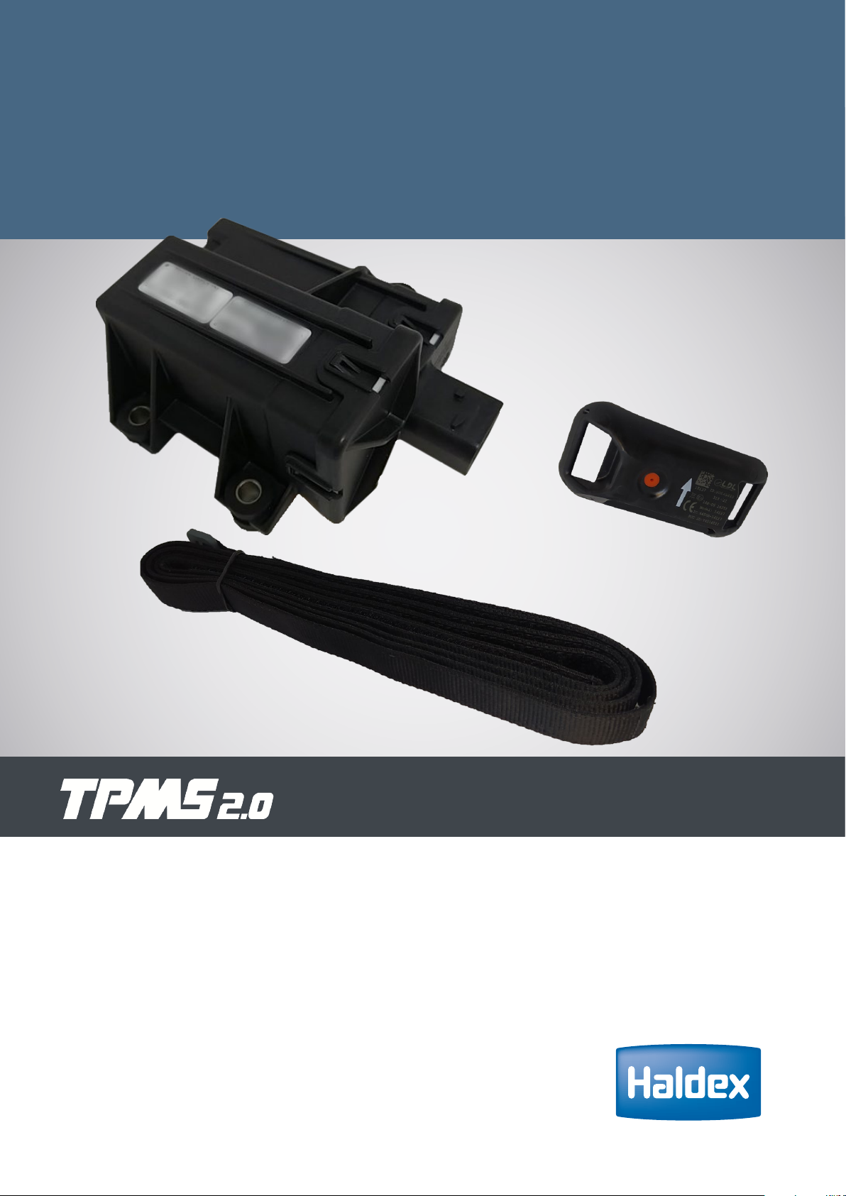
Receiver control unit (RCU)
The RCU receives sensor information, determines the system status, and
sends it to the EBS via the trailer CAN.
Wheel unit sensor (WUS)
The TPMS 2.0 wheel unit sensor (WUS) is a pressure sensor which is
clamped inside the tire using a velcro belt. It measures the pressure and
temperature inside the tire and transmits all the measurements by radio
frequency (RF) to the RCU.
Belt assembly
A velcro belt is used to attach the WUS (042727219) to the tire rim. One
belt part number covers all rim sizes from 17.5'' to 24.5''
WUS Sole (optional)
The sole should be used / clipped onto the WUS for smaller diameter rims,
which have a small drop centre width from 25 mm to 40 mm.

TPMS 2.0Installation guide
7
2023 Innovative Vehicle Solutions
P/N 815 063 001
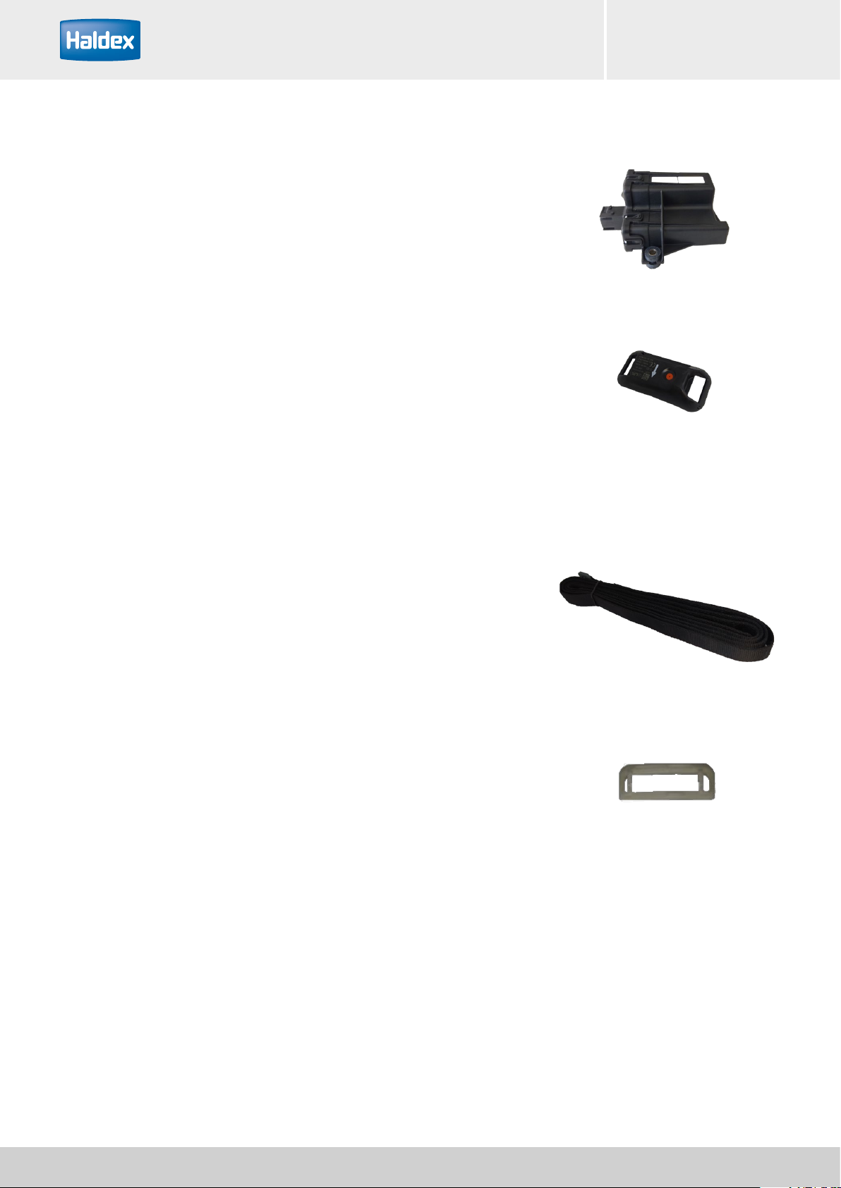
TPMS 2.0 Smart DIAG Tool
The TPMS Smart diagnostic tool is a tool used to send
a low frequency (LF) trigger to the WUS. This tool is
operated by an Android mobile phone application.
It is used to configure the system for the first time,
writing the trailer configuration (number of wheels
and axles), recommended pressure per axle, warning
thresholds and WUS positions into the RCU.
TPMS 2.0 Smart Box
The TPMS 2.0 Smart Box is connected to the mobile
phone and used to read the TPMS wheel sensor ID's.
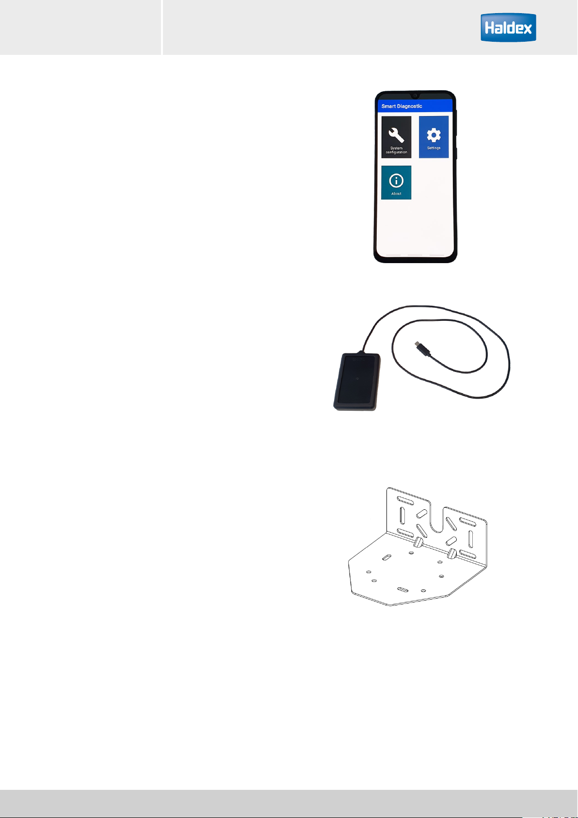
Bracket
Bracket as per "Bracket specifications" on page 22

TPMS 2.0 Installation guide
8Innovative Vehicle Solutions 2023
TPMS 2.0 label
Indicate the presence of a WUS in the wheel by
sticking the TPMS label onto the wheel rim next to the
valve. The WUS must be located by eye before the tire
is removed from the rim.
Valve indication
Indicate the presence of a WUS in the wheel by fixing
a plastic colored tube (blue or other) onto the wheel
valve nose.
P/N 006700021_M
The TPMS 2.0 wheel unit sensor (WUS) can be mounted on all tire rims compliant to national and international
tire standards from 17.5 up to 24 inches diameter.
Tire standards:
› European tire and rim technical organisation (ETRTO)
› Tire and rim association (TRA)
› Japan automobile tire manufacturers association (JATMA)
For all rims which do not respect these specifications, customer must send all rims drawings for Haldex Brake
Products for approval.
Mounting the WUS (Belt version)
TPMS 2.0 indicator

TPMS 2.0Installation guide
9
2023 Innovative Vehicle Solutions
Examples of major mounting
problems
Example 1
There is a limitation of the mounting of the WUS on
small width drop centre tire rims.
Do not mount the WUS, if the flat width available in
the drop centre is below 25 mm.
Mount the WUS with the sole, if the flat width
available in the drop centre is between 25 mm to 40
mm.
Mount the WUS without the sole, if the flat width
available in the drop centre is larger than 40 mm.
Larger than 40 mm = OK to mount the WUS without the sole
OK
Larger than 25 mm = OK to mount the WUS with the sole
OK
OK
Flat width 25 - 40 mm = Not OK to mount the WUS without the sole

TPMS 2.0 Installation guide
10 Innovative Vehicle Solutions 2023
Example 2
Mounting with a wrong position on a conical rim profile.
Note: The angle between the sensor and the wheel axis must stay below 15° in order to avoid bad acquisition of
the acceleration level by the sensor. Also the more the sensor is raised from the rim, the greater the tire can catch
it during mounting / dismounting phase.
On a conical rim
profile, always locate
the TPMS 2.0 WUS on
the lower perimeter to
avoid sliding
Sliding under vibration
Attaching the sole adaptor (optional)
For small diameter rim with small drop centre width (25 mm minimum): => clip the sole onto the housing of the
WUS before introducing the belt in windows.

TPMS 2.0Installation guide
11
2023 Innovative Vehicle Solutions
Mounting the wheel unit sensor
Precaution before mounting operation
› Do not use the wheel unit sensor after a drop of
more than 1 meter
› Storage temperature between 0°C and 30°C
› It is forbidden to use water pressure jet on the WUS
Mounting procedure
A. Assemble the belt strap to the WUS case. The
belt strap is introduced first into the window N°1,
running under the case and pass through window N°2.
Carefully set the loop side of the strap away from the
rim. Pass through the reversal buckle and tighten the
strap firmly before closing the velcro system. The final
position of the WUS belt is at 12h, or 180° from the
valve (steps 1-9).
B. Proceed to the Velcro closing by a sliding press with
your thumb, complete 3 round trips along the velcro
system, this optimizes the attachment of the velcro
(step 10).
C. If you can move the sensor under finger stress
(Approx. 40N), tighten the strap and return to point B
D. The belt is designed to withstand 8 years of usage
and ensure 30 velcro’s mounting / dismounting
operations. It is mandatory to replace the belt with a
new belt when the old one has more than 8 years or
30 velcro’s mounting / dismounting.
E. During a tire dismounting, inspect the belt. If the
belt shows cuts or fiber destruction done by mounting
tools, it is mandatory to remove it and use a new belt.
F. The belt is designed to withstand automotive fluids,
nevertheless it is forbidden to clean the belt with
petroleum or solvents, only cleaning with soap and
rinsing with tap water is authorized.
Orientation
(See separate WUS
section page 12)

TPMS 2.0 Installation guide
12 Innovative Vehicle Solutions 2023
Wheel Unit Sensor (WUS) orientation
When installing the wheel unit sensor (WUS) onto the
tire rim, ensure that the orientation according to the
"embossed arrow" marking on the WUS is followed.
Fitted WUS orientation shown by WUS orientation arrow
Semi Trailer
Semi Trailer - twin wheels

Twin wheels mounting
Important: It is recommended to mount the twins
wheels with an angle shift about 180°. Therefore
on this couple of wheels, wheel units are set as far
as possible from each other (this position offers an
optimized radio frequency performance).
Super single rims
Mounting a wheel unit sensor to a super-single rim.
In the case of radial valve hole (ex: Super single rim),
the cable must be located in the drop centre. Never set
the cable onto the valve air flow channel.
Cable location on the tire rim
WUS on external
wheel
WUS on internal
wheel
Vehicle axis
TPMS 2.0Installation guide
13
2023 Innovative Vehicle Solutions

Tire mounting precautions
Tire mounting should only be completed by a qualified tire technician.
Before any mounting operation of the tire, make sure that the WUS has been correctly mounted and tightened to
the rim. If the WUS moves more than 10 mm in the drop centre of the rim well under transversal stress about 6
Kg, do not mount the tire, and the WUS must be installed again.
Application by spraying the tire mounting soap lubricant is possible, if the viscosity of the product stays below
800 mPa.s (milli Pascal-second) at -10°C to 100°C. No lubrication product or any other matter may partially or
completely cover the pressure measuring hole of the wheel unit sensor. Always avoid direct lubrication onto the
WUS.
Mounting the tire
Mounting of the tire
During the tire mounting, avoid any contact of the
sensor by the tire.
Step 1
The tire hanged on rim gives gap @ 180° between
WUS and tire bead contact with rim, in this condition,
the first tire bead can be introduced by a foot push or
machine push without hurting sensor.
Introduce the first side of the tire on the rim avoiding
contact with the WUS, the first tire bead jumps into
the rim after a wheel rotation about 90°. Be sure that
the first side wall of the tire has passed over the WUS
before starting to introduce the second side wall of the
tire.
Step 2
Mounting tool (static). For second bead mounting
The second tire wall is assembled avoiding any contact
between the tool and the WUS.
Key:
1Tire
2Tire valve
3Wheel spin direction on the mounting machine
4WUS
5Mounting tool (static) or foot push
6Rim
Step 1
1
2
3
4
5
6
Valve position at 12h for start
of first flank mounting.
Step 2
1
2
3
4
5
6
Valve position for starting
second flank mounting.
TPMS 2.0 Installation guide
14 Innovative Vehicle Solutions 2023

Tire removal precautions
Tire removing should only be completed by a qualified tire technician.
If using a machine or manual method to remove the tire from the rim, the operator must look for the WUS (TPMS
2.0 sensor) in the drop centre of the rim well when the first side wall is pushed enough. This is to ensure that the
WUS is not damaged by the machine or tire. This process should start from the tire valve.
Removing the tire
Operator using the rotational tool to push out the tire
from the rim.
The operator has must look for the WUS (TPMS 2.0
sensor) in the drop centre of the rim well when the
first side wall is pushed enough. This is to ensure that
the WUS is not damaged by the machine or tire. This
process should start from the tire valve.
When the second side wall is being removed, first push
the wall enough to give the operator a visual access to
the WUS (TPMS 2.0 sensor). The transversal speed of
the bead loosener must be equal to zero, with the tire
and rim still rotating. As soon as the operator detects
the WUS, they must launch the final dismounting,
using the rotation tool.
1 - WUS visual detection
2 - Launch the final
dismounting step
Removing the tire from the rim
TPMS 2.0Installation guide
15
2023 Innovative Vehicle Solutions

Receiver Control Unit (RCU)
In compliance with UNECE Regulation 141, the TPMS 2.0 RCU will warn the driver in the event of a low-pressure
or TPMS malfunction.
A maximum of 12 wheel unit sensors can be programmed to 1 RCU – if more wheels are required per trailer,
additional RCUs (up to 3) can be linked together. See possible configurations on page 18.
Conguring the system
To configure the system, the Haldex TPMS Smart DIAG phone application is to be used. See page 42 for more
detailed instruction on its use.
The overview is as follows:
› The RCU is plugged into the EB+ 4.0 EBS and powered.
› The appropriate configuration is selected by the user.
› The recommended pressure and warning thresholds per axle can be adjusted according to the tyre
manufacturers / OEM recommendations.
› The Smart box tool is used to trigger the RCU(s).
› The Smart box tool is used to trigger each WUS in turn, paying attention to the position of each.
› The configuration is written into the RCU(s).
Description Part number Drawing
TPMS 2.0 RCU 815 058 001 815 058 000 2
TPMS 2.0 Installation guide
16 Innovative Vehicle Solutions 2023

Warnings from TPMS
Low Pressure
The low pressure warning is mandatory to achieve compliance with UNECE R141. This will raise a warning at a
user configurable threshold (minimum 80%) below the recommended tire pressure. This will raise a malfunction
lamp.
High Temperature
The high temperature warning will raise a warning at a user configurable value. This will NOT raise a malfunction
lamp.
Over Pressure
The over pressure warning will raise a warning at a user configurable threshold above the recommended tire
pressure This will NOT raise a malfunction lamp.
TPMS Malfunction
The TPMS malfunction is mandatory to achieve compliance with UNECE R141. This will raise a warning after 10
minutes of no communication with a WUS. This will raise a malfunction lamp.
Automatic Learning
If a wheel in an already-configured system is to be swapped, the system is capable of automatically learning that
a new WUS ID has joined the system.
The automatic learning feature will place the position of the newly learned ID in the ‘empty’ position.
Occasionally, if the reception of the new WUS is not optimal, the automatic learning will take longer than 10
minutes and, therefore, the TPMS malfunction lamp will be illuminated due to loss of communication with a
WUS. It will be soon extinguished upon confirmation of the learned WUS ID.
TPMS 2.0Installation guide
17
2023 Innovative Vehicle Solutions

Config
No.
No. of
axles
Number of wheels per axle Total
no. of
sensors
No. of
RCUs
required
No. of
supported
spares
Axle 1
(front)
Axle 2 Axle 3 Axle 4 Axle 5
1 1 2 2 1 2
2 1 4 4 1 2
3 2 2 2 4 1 2
4 2 2 4 6 1 2
5 2 4 2 6 1 2
6 2 4 4 8 1 2
7 3 2 2 2 6 1 2
8 3 2 2 4 8 1 2
9 3 2 4 2 8 1 2
10 3 2 4 4 10 1 2
11 3 4 2 2 8 2 4
12 3 4 2 4 10 2 4
13 3 4 4 2 10 2 4
14 3 4 4 4 12 2 4
15 4 2 2 2 2 8 2 4
16 4 2 2 2 4 10 2 4
17 4 2 2 4 2 10 2 4
18 4 2 2 4 4 12 2 4
19 4 2 4 2 2 10 2 4
20 4 2 4 2 4 12 2 4
21 4 2 4 4 2 12 2 4
22 4 2 4 4 4 14 2 4
23 4 4 2 2 2 10 2 4
24 4 4 2 2 4 12 2 4
25 4 4 2 4 2 12 2 4
26 4 4 2 4 4 14 2 4
27 4 4 4 2 2 12 2 4
28 4 4 4 2 4 14 2 4
29 4 4 4 4 2 14 2 4
30 4 4 4 4 4 16 2 4
31 5 2 2 2 2 2 10 2 4
32 5 2 2 2 2 4 12 2 4
33 5 2 2 2 4 2 12 2 4
34 5 2 2 2 4 4 14 2 4
35 5 2 2 4 2 2 12 2 4
36 5 2 2 4 2 4 14 2 4
37 5 2 2 4 4 2 14 2 4
38 5 2 2 4 4 4 16 2 4
RCU Conguration table
TPMS 2.0 Installation guide
18 Innovative Vehicle Solutions 2023

Part Material Characteristic
RCU All electronic parts -
1 Housing Thermoplastic Black
1 Cover Thermoplastic Black
3 Silent-blocks EPDM Black
3 Spacers Stainless steel Up to M6 screw
Housing
Cover
Spacer
Silent Block
TPMS 2.0Installation guide
19
2023 Innovative Vehicle Solutions

RCU Location
The RCU must be free from any metallic shield in the direction of the road (between the road and the RCU). The
antenna should be cleared as possible to optimize RF communication and reduce areas of non-receipt.
RCU uses an internal RF antenna for receiving TPMS 2.0 message from sensors, RF antennas are very sensitive
to close objects (especially metallic objects / obstructions / shields include harnesses / cables etc), that’s why it’s
mandatory to keep a minimum clearance about 5cm around RCU as shown on the figure below.
RF Antenna location
+ X = 5 cm
+ Y = 5 cm
- Y = 5 cm
- X = 5 cm
Note: Radio frequency reception are disturbed by the presence of metallic objects.
TPMS 2.0 Installation guide
20 Innovative Vehicle Solutions 2023
Table of contents
Other Haldex Diagnostic Equipment manuals