Hammar HM-0600 User manual

HK-41702
INSTALLATION MANUAL
HM-0600
LIFEBUOY RELEASE SYSTEM Mk II
Complete package for electric/water release

HK-41702
3. Mount the connector box close to the GRP holder. Make sure that the cable from the ERU is long enough to reach the connector box.
The connector box shall be mounted with the cable glands horizontal in order to avoid water ingress. Always tighten the cable glands.
4. Mount the Release Switch in an easy to locate and manage position on the bridge. The Release Switch shall always be mounted
inside the wheelhouse or bridge.
5. Install the screened cable from the connector box to the Release Switch and connect the black ERU cable to the connector box.
6. Connect 24V emergency power supply to the Release Switch. Ensure that you follow the enclosed connection drawing. Test the
electrical installation according to instructions on the drawing or the enclosed document ”Test of the Lifebuoy Release System”.
7. The ERU is pre-installed. The ERU must be marked with its expiry date. Markings must be done solely by a manufacturer of liferafts
or an authorised liferaft service station. The expiry date is 2 years, or otherwise stated on the product, from month of installation
onboard. The release unit is labelled with a marking for year and month. Use a knife and carefully scratch away the appropriate
square for month and year of expiry.
8. Put a lifebuoy 2/3 into the GRP holder and then secure it for the installation phase. Use the supplied thin white pilot line to pull the
release cord through the ERU unit.
INSTALLATION
1. Mount the GRP holder in a position so that a released lifebuoy will easily fall into the water.
2. Follow the instructions for the mounting bolts in accordance with the pictures. Make sure that you mount double washers between
frame or bulkhead and the GRP holder.

HK-41702
Make sure that the lifebuoy line is not on the outward side of the release cord! This might entangle the lifebuoy in an activation situation.
9. Pull up the release cord through the ERU hole with the pilot line. Secure it with the manual safety pin.
10. Connect the power to the Release Switch.
11. The safety cover on the Release Switch shall be secured with some kind of easy-to- break seal, in order to avoid unintentional use of
the system.
12. The system is now ready for use. The ERU shall be changed after two years of service.

HK-41702
TESTING THE MECHANICAL RELEASE FUNCTION
1. Remove the manual safety pin holding the release cord.
2. The Lifebuoy will be released and launched from the GRP holder.
TESTING THE ELECTRONIC RELEASE FUNCTION BY USING THE EMULATOR HM-0467
1. Open the enclosure of the Emulator and attach two connection wires to the terminals on the Emulator.
(Do not use to much torque on the terminal screws)
2. Push the push button on the circuit board to switch on the Emulator. The red and the green LED on the circuit board shall light up
simultaneously. The green LED will start ashing green and the device is ready to be used.
3. Open the Connector box (mounted close to the GRP holder) and disconnect the exible cable of the H20 ERU. Connect the two
connection wires from the Emulator to the terminals on the Connector box, were the exible cable was mounted. (The polarity is not
important).
The Emulator can be left without observation mounted to the Connector box, as the Emulator will hold the indication of the
LED turning from green to red if activated until the device is reset manually.
4. Push the Release Switch (should be mounted on the bridge or inside the wheelhouse) to activate the output of the Lifebuoy Release
unit. The Emulator’s LED will change from LED ashing green to LED ashing red if the output has been activated and the system is
functional.
DO NOT FORGET TO RECONNECT THE H20 ERU AND THE SAFETY PIN AFTER THE TEST!
TEST OF THE LIFEBUOY RELEASE SYSTEM

HK-41702
COMPONENTS
PACKAGE
Part no.
HM-0600
1. One GRP holder with pre-installed metal spring holder. The GRP holder can
be mounted on port or starboard side of the ship and no change of the
metal spring holder is needed. Measurements and hole positions - please
check enclosed drawing.
2. One ERU (electric remote unit) with cord pre-installed on the metal holder.
The ERU cable is 1,5m long and shall be well strapped to the GRP holder in
order to avoid any damage by weather or wind.
3. One Release Switch in protective box to be mounted at the wheelhouse or
bridge, IP66 class. Colour: silky grey. If mounted outside it shall be protected
by an outer protective enclosure. Maximum diameter for cable 12mm. If
the Release Switch shall be mounted ush in a bridge control panel please
specify in the order - HM-0451 Release Switch for ush mounting. Measure-
ments and hole position - please check enclosed drawing.
4. One connector box in marine grade plastic, IP66 class. Colour: steel grey.
Maximum diameter for cable 12mm. Measurements and hole positions -
please check enclosed drawing.
5. 20m cable from connector box to release switch, marine approved, scree-
ned 2 x 0,75mm2, diameter 8mm. Longer lengths can be supplied on
request by additional meter price. Maximum length of the installation is
150m. The Hammar products are designed to handle any voltage drop, so
there is no need to increase the cable dimensions more than our recom-
mendation.
Cable recommendations:
0 - 75m installation length: 2 x 0,75mm2
75 - 150m installation lenght: 2 x 1,5mm2.
Cables with a diameter larger than 12mm can not be handled in the cable
glands and terminal blocks. Electric power required is 24VDC emergency
power.
6. One manual safety pin in stainless steel.
7. One pilot line for loading the lifebuoy.
8. Installation manual and user guide.

HK-41702
SPARE PARTS
Part no.
HM-0620 Lifebuoy metal spring
holder only.
HM-0630 Replacement kit for Lifebuoy
System MkII, ERU electric/
water activation - HM-0600
with release cord and instal-
lation manual in English.
HM-0660 Replacement kit for Lifebuoy
System MkII, MRU vacuum
operated - HM-0650 with
release cord and installation
manual in English.
HM-0406 Replacement kit for LifeBuoy
System MkI, ERU electric/
water activation - HM-0500
with release cord, metal
ring, cable tie and installa-
tion manual in English.
COMPONENTS
OPTIONS AVAILABLE
Part no.
HM-0610 LifeBuoy Release system,
only manual release.
HM-0650 LifeBuoy Release System,
vacuum pump operated
system.
ATEX approved products are available, please contact Hammar for further information.

HK-41702
Sideview Backview Frontview Topview
190
780
958
510
650
60
800
160
60
670
680
540
M8(x5)
GRP HOLDER DRAWING

HK-41702
55
55 38 45
45
4,30
Front side Back
tor.c
tor.c
1
CM HAMMAR AB
Tel.: +46 31 709 65 50 Fax.: +46 31 49 70 23
Drawn/Ritad Checked/Kontr. Appr./Godkänd Scale/skala Repl./Ersätter: Date/Datum: (dd-mm-yyyy)
Draw.No./Ritn.nr.
Det. Number/ant. Designation/benämn.
Sheet1
Notes/noteringar
Material
tor.c 10-07-2009
A010007-01
1:1
CONNECTOR BOX ERU
Rev.:
1
of
CONNECTOR BOX DRAWING

HK-41702
7
87
87
tor.c
tor.c
1
CM HAMMAR AB
Drawn/Ritad Checked/Kontr. Appr./Godkänd Date/Datum:
Repl./Ersätter:
Scale/skala
Draw.No./Ritn.nr.
Det. Number/ant. Designation/benämn. Material Notes/noteringar
RELEASE SWITCH - DIMENSIONS
Sheet1
A010031
tor.c 10-07-2009
1:1
Tel.: +46 31 709 65 50 Fax.: +46 31 49 70 23
Rev.:
1
of
82
MAXIMUM DIAMETER FOR CABLE 12 mm
102
102
RELEASE SWITCH BOX DRAWING

HK-41702
Optional connection to ERRS System, Terminal No:
1 to +24VDC EMERGENCY POWER SYSTEM
4 to 0VDC EMERGENCY POWER SYSTEM
2 to + output ERRS System (upper terminals 1-10 in ERRS control box)
5 to - output ERRS system (Lower terminals 1-10 in ERRS control box)
POWER SUPPLY, Terminal No:
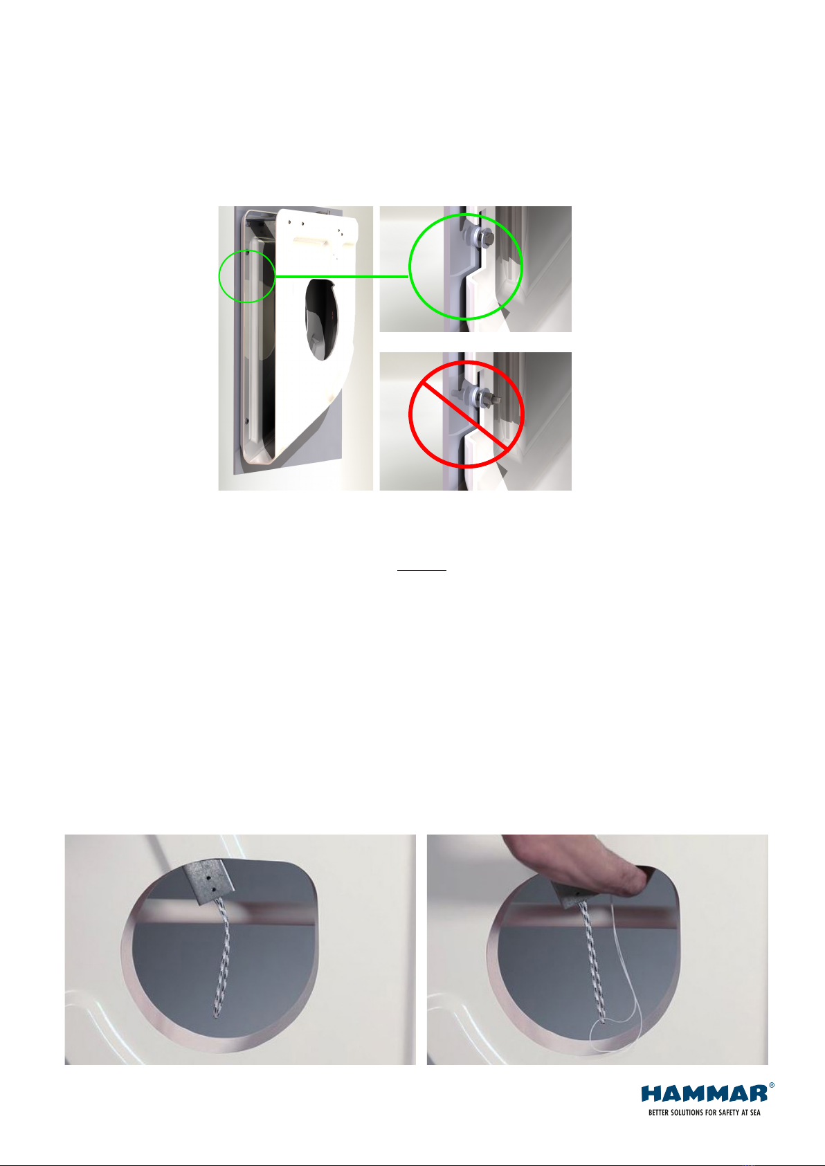
TESTING THE INSTALLATION:
The correct function of the HAMMAR ERU RELEASE SWITCH can be tested by
Note 3
connecting a 200 mAF 5x20 mm glass tube fuse to the ERU RELEASE SWITCH
output instead of the pos. 1 ERU unit. The fuse blows off when the ERU RELEASE
SWITCH push button is pressed if the system is correctly installed.
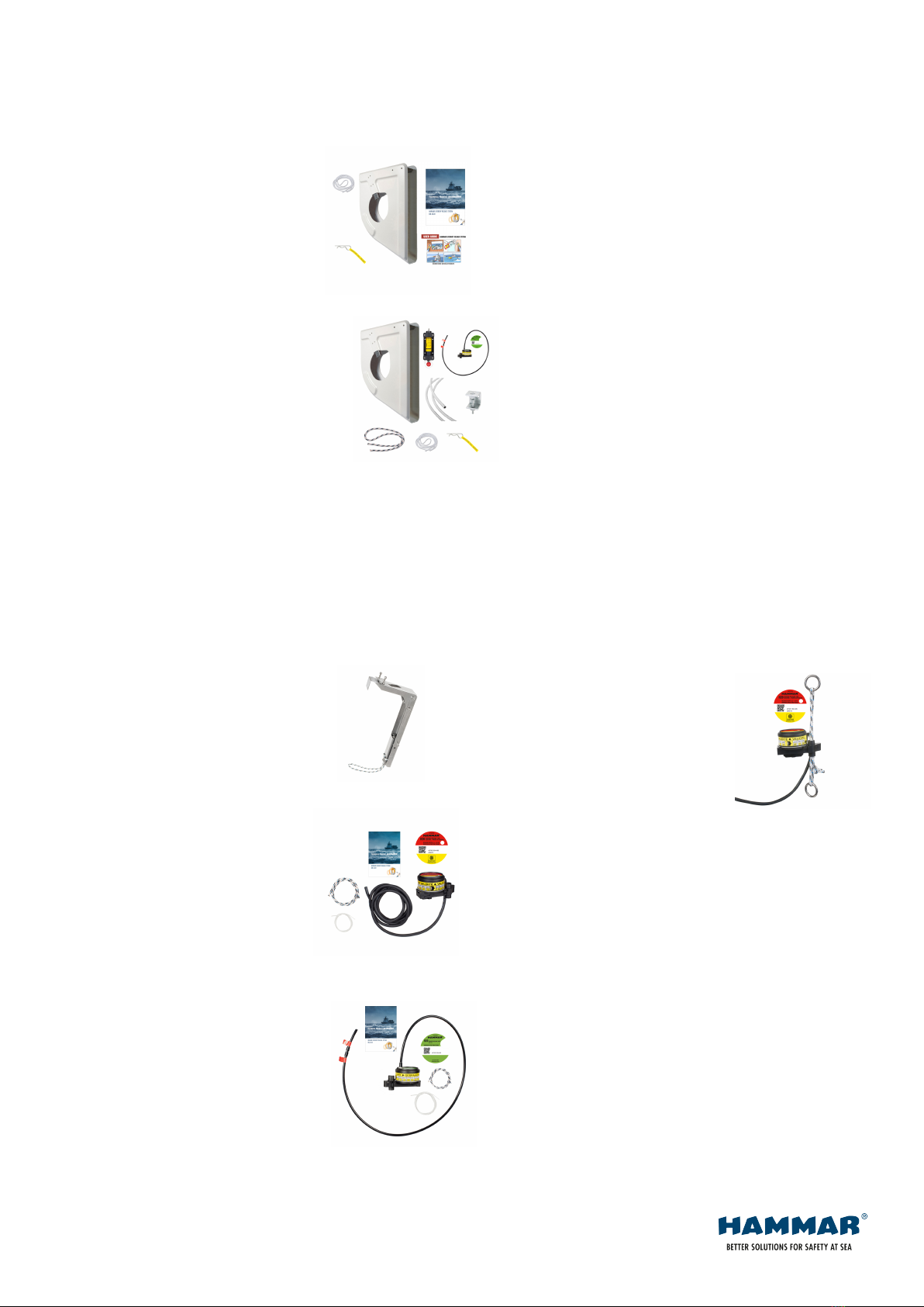
POS 1: HAMMAR ELECTRIC RELEASE UNIT (H20 ERU)
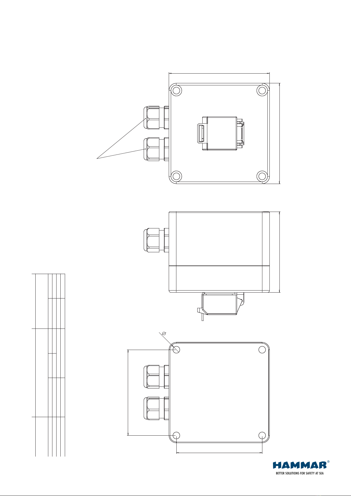
POS 2: HAMMAR ERU CONNECTION BOX
Cable glands, max cable diameter 10 mm
Terminals: max cable area 2,5 mm2
POS 3: HAMMAR ERU RELEASE SWITCH with integrated push button
Input voltage 18VDC - 32VDC, Max. intermittent load 3A
Cable glands, max cable diameter 12 mm
Terminals: max cable area 2,5 mm2
POS 4: Cable, 2 x min. 0,75 mm2 (screened). Outer diameter max.10 mm
POS 5: Cable, 4 x min. 0,75 mm2 (screened). Outer diameter max.12 mm
or
Cable, 2 x min. 0,75 mm2 (screened). Outer diameter max.12 mm
Note 1: When connecting the cable from the H20 -ERU to the CONNECTION BOX,
the polarity of the wires is of no importance.
Note 2: Connect the screen of the cables inside the Release switch enclosure
Note 3: Connect the screen of the power supply cable to ships ground Sheet1 1
CM HAMMAR AB
Drawn/Ritad Checked/Kontr. Appr./Godkänd Date/Datum: (dd-mm-yyyy)
Repl./Ersätter:
Scale/skala
Draw.No./Ritn.nr.
Det. Number/ant. Designation/benämn. Material Notes/noteringar
tc
Tel.: +46 31 709 65 50 Fax.: +46 31 49 70 23
24VDC - CONNECTION DIAGRAM ERU1001
tc 03-10-2007
Rev.:
7
tc
HAMMAR H20 ERU - RELEASE SWITCH
of
3
4
1
2
5
Note 1
7
module
123456
1: +24VDC
4: 0VDC
3: +ERU outp.
6: - ERU outp.
5: - ERRS (optional)
2: + ERRS (optional)
Elect.
Note 2
WIRING CONNECTION DIAMGRAM ERU
This manual suits for next models
2
Table of contents
Other Hammar Safety Equipment manuals