Handicare SystemRoMedic EvaDrive User manual

60900012
60900013
60900002
60900003
Manual no: 677 En Rev 2
Service manual - English
Safety information
Visual inspection
Inspect lift functions regularly. Check to ensure that material is free from damage.
Before use
Make certain the lift is properly assembled.
Check lifting function and base-width adjustment.
Check driving function in all directions.
Check that the accessory (EvaDrive) is properly mounted on the lift.
Always read the user manuals for all assistive devices used during a transfer.
Keep the user manual where it is accessible to users of the product.
Always make sure that you have the right version of the user manual.
The most recent editions of user manuals are available for downloading from our website, www.handicare.com.
Under no circumstances may a lift with EvaDrive be used by persons who have not received instruction in the operation
of a lift with the accessory mounted.
It is strongly prohibited to modify the original product.
Always read the user manual
SystemRoMedicTM
EvaDrive

Table of contents
Assembly
Final inspection....................................................................................... 3
Using the product
Important information ............................................................................. 4
Trouble-shooting ..................................................................................... 5
Exploded view ............................................................................. 6-8
Spare parts................................................................................10-14
Changing spare parts.........................................................................12-14
Adjusting Toe-in/Toe-out ......................................................15
Periodic inspection - protocol......................................................16
Description of periodic inspektion ............................................................17
Periodic inspection - instruction...............................................................18
Maintenance ..................................................................................19
Technical information ................................................................20
Symbols ................................................................................................21
Dimensions.......................................................................................22-23
Appendix 1: Error codes.....................................................24-26

3
SERVICE MANUAL
SystemRoMedicTM
Final inspection
• Check to ensure that no components are left in the packaging.
• Inspect the product for signs of damage.
• Inspect wheels and brakes.
• Check mechanical brake function by activating the brakes and, without activating EvaDrive, try to
move the lift forward. If the lift does not move, the brakes function as they should.
• Check all connections, screws and bolts.
• Check emergency-stop function by activating EvaDrive; press the emergency-stop button, and
then press the up or down button. If nothing happens, the emergency stop is functioning as it should,
since it stops all electrical functions.
• Using the hand control, activate EvaDrive, press the up button and run the lift boom all the way up.
Then, press the down button and run the boom all the way down.
• Test base-width adjustment. Activate the system, press the button for base-width adjustment, open
the undercarriage to maximum width, and then press the other button to reduce the width.
• If the lift is functioning as it should, connect the charger and check to ensure that the charging
indicator light on the control panel lights up.
• Activate EvaDrive and grasp the handlebar with both hands, hold the safety switch in, and then run
the lift forward, backward and in a turning motion. Check that the lift moves easily, to both the right
and to the left.
• Test the rear wheels by turning them a bit; turn the lift back and forth. Turn the wheels all the way and
run the lift sideways. Check that the yellow light lights up when the wheels turn and are turned, and
that the light goes out when the wheels are returned to the normal position.
NOTE!
The lift must be charged for at least 10 hours before it is used for the first time. See section on battery charging.
Keep the manual where it is easily accessible for users of the product.

Using the product
Important information
• The accessory must be assembled according to the assembly instructions included with the product.
• The lift, with the accessory installed, may only be operated indoors on a dry and level surface.
• Never leave a user unattended during a transfer.
• Maximum load may under no circumstances be exceeded. See section on maximum load.
• The lift must not be lowered into water or used in the shower.
• The lift must not be left or stored in a damp or humid environment.
• The lift must not be charged in a wet room.
• For optimal function, inspect the lift regularly. See section on Maintenance.
• Warranty applies only if repairs or alterations are made by authorized personnel.
• Never attempt to lift the mobile lift unit by the handlebar.
• Ensure that there are no obstacles or people in the way of the lift.
• Never stand on the lift during operation. Always walk behind the lift.
• Low speed is recommended when a user is seated in a sling attached to the lift.
• The lift must not be used in oxygent-enriched environments.
• Handle the battery with care. Do not drop.
• Use only batteries, cables and chargers intended for EvaDrive.
• If a lift is attempted at an angle, a safety function will temporarily pause the lifting motion. Ensure that
the EvaDrive is correctly positioned over the user, or let the EvaDrive position itself with the brakes
unlocked. Once the lift is in its correct position, the lifting motion will automatically be resumed.
4USER MANUAL SystemRoMedicTM

5
SERVICE MANUAL
SystemRoMedicTM
Troubleshooting
The green light blinks, but stops after a while. Automatic calibration complete
The green light blinks. - Manual calibration is required, see section on manual
calibration.
- Check to ensure that no load was applied to the
handlebar when the lift was started e.g., that nothing was
hanging on the handlebar. In that case, remove it and the
green light will stop blinking.
All or parts of the battery scale blink quickly. Something is wrong with the lift’s electrical system.
Restart EvaDrive. If there is still a problem, contact
Handicare.
Red light + battery scale blink - Restart
- Contact Handicare
If unusual sounds are heard: - Try to locate the source of the sound.
- Take the lift unit out of service and contact Handicare.
The lift cannot be started - Check the battery switch.
- Check battery connection.
- Connect charger and charge for at least 2 hours.
- Contact Handicare.
Resetting service indicator
• The handle should be ON.
• Press and hold the start button untill the service indicator starts flashing (aprox 2 sec. )
• Without releasing the start button, press down both of the manouver buttons for the rear wheels and hold
untill the service indicator is turned off (aprox. 5 sec).

2
3
1
5
786
4
12
9
11
10
13
REVISION HISTORY
REV.
POS.
DESCRIPTION
DATE
DRAWN BY
ITEM
NO.
DOCUMENT
NO.
REV.
TITLE
QTY.
1
90005037
00D+
Eva Drive 450 base assy
1
2
90005021
00C+
EvaDrive Hinge assembly
1
3
90003290
00+
Battery EvaDrive
1
4
90005041 03
Battery Plate EvaDrive
1
5
90003939
00+
ED cables
1
6
90003270 00A
Cover leg
2
7
90005007 01
Spacer 8x12x6
2
8
90003073
01A+
Converter Nut EvaDrive
2
9
90000697 02
Screw M6S DIN931 8.8 M10x16H
fzb
1
10 90000539 02
Lock nut DIN 985 CL6 M10 FZB
1
11 90000601 01
Washer DIN125 10.5x20x2 fzb
2
12 90000660 01
Nut cover MSM10
2
13 90000789
00B
Screw MLC6S DIN7984 8.8 M5x8
2
D
E
F
C
1
2
3
4
B
A
3
2
1
5
C
D
4
6
7
8
A
B
This drawing and any information or descriptive matter set out hereon are the confidential and copyright property of Handicare
and must not be disclosed, loaned, copied or used for manufacturing, tendering or any other purpose without their written permission.
00+
SCALE
PROJECTION
MATERIAL SPECIFICATION:
A3
2015-11-11
90005038
Eva Drive 450 kit
In work
SIZE
MATERIAL:
TITLE
STATUS
WEIGHT:
SHEET 1 OF 1
CREATED
DATE
NAME
REV.
DWG. NO.
1:5
5
6
E
hc-matfre
2
3
1
5
786
4
12
9
11
10
13
REVISION HISTORY
REV.
POS.
DESCRIPTION
DATE
DRAWN BY
ITEM
NO.
DOCUMENT
NO.
REV.
TITLE
QTY.
1
90005037
00D+
Eva Drive 450 base assy
1
2
90005021
00C+
EvaDrive Hinge assembly
1
3
90003290
00+
Battery EvaDrive
1
4
90005041 03
Battery Plate EvaDrive
1
5
90003939
00+
ED cables
1
6
90003270
00A
Cover leg
2
7
90005007 01
Spacer 8x12x6
2
8
90003073
01A+
Converter Nut EvaDrive
2
9
90000697 02
Screw M6S DIN931 8.8 M10x16H
fzb
1
10
90000539 02
Lock nut DIN 985 CL6 M10 FZB
1
11
90000601 01
Washer DIN125 10.5x20x2 fzb
2
12
90000660 01
Nut cover MSM10
2
13
90000789
00B
Screw MLC6S DIN7984 8.8 M5x8
2
D
E
F
C
1
2
3
4
B
A
3
2
1
5
C
D
4
6
7
8
A
B
This drawing and any information or descriptive matter set out hereon are the confidential and copyright property of Handicare
and must not be disclosed, loaned, copied or used for manufacturing, tendering or any other purpose without their written permission.
00+
SCALE
PROJECTION
MATERIAL SPECIFICATION:
A3
2015-11-11
90005038
Eva Drive 450 kit
In work
SIZE
MATERIAL:
TITLE
STATUS
WEIGHT:
SHEET 1 OF 1
CREATED
DATE
NAME
REV.
DWG. NO.
1:5
5
6
E
hc-matfre
2
3
1
5
786
4
12
9
11
10
13
REVISION HISTORY
REV.
POS.
DESCRIPTION
DATE
DRAWN BY
ITEM
NO.
DOCUMENT
NO.
REV.
TITLE
QTY.
1 90005037
00D+
Eva Drive 450 base assy
1
2 90005021
00C+
EvaDrive Hinge assembly
1
3 90003290
00+
Battery EvaDrive
1
4 90005041 03
Battery Plate EvaDrive
1
5 90003939
00+
ED cables
1
6 90003270
00A
Cover leg
2
7 90005007 01
Spacer 8x12x6
2
8 90003073
01A+
Converter Nut EvaDrive
2
9 90000697 02
Screw M6S DIN931 8.8 M10x16H
fzb
1
10 90000539 02
Lock nut DIN 985 CL6 M10 FZB
1
11 90000601 01
Washer DIN125 10.5x20x2 fzb
2
12 90000660 01
Nut cover MSM10
2
13 90000789
00B
Screw MLC6S DIN7984 8.8 M5x8
2
D
E
F
C
1
2
3
4
B
A
3
2
1
5
C
D
4
6
7
8
A
B
This drawing and any information or descriptive matter set out hereon are the confidential and copyright property of Handicare
and must not be disclosed, loaned, copied or used for manufacturing, tendering or any other purpose without their written permission.
00+
SCALE
PROJECTION
MATERIAL SPECIFICATION:
A3
2015-11-11
90005038
Eva Drive 450 kit
In work
SIZE
MATERIAL:
TITLE
STATUS
WEIGHT:
SHEET 1 OF 1
CREATED
DATE
NAME
REV.
DWG. NO.
1:5
5
6
E
hc-matfre
Exploded view and components - EvaDrive
6SERVICE MANUAL SystemRoMedicTM

7
SERVICE MANUAL
SystemRoMedicTM
21
4033
4
131418
1
2
8
2016 10 11 22
756
31
30
3
17
9
2928
27 24
19
23
15
26
25
39 32
12
34
35
37
36
38
REVISION HISTORY
REV.
POS.
DESCRIPTION
DATE
DRAWN BY
ITEM NO.
DOCUMENT NO.
REV.
TITLE
QTY.
1 90004710
01A+
EvaDrive leg right welded
1
290004711
01A+
EvaDrive leg left welded
1
390000345 04
Washer DIN125 8.4x16x1.6 fzb
4
490004723
01A
Eva drive actuator stearing pin
1
590004718 01
Eva drive wheel bracket left
1
690004466
00B+
Hub motor and wheel left
1
790004737
00A+
Bushing teflon COB010_DB16
4
890004734
00+
Lock nut DIN985 M18 fzb
2
990004720 01
Eva drive wheel distance
2
10 90004719 01
Eva drive wheel bracket right
1
11 90005035
00A+
Parallell key DIN 6885 A RK h9 4x20
2
12 90000026 03
Lock nut DIN985 M8 fzb
10
13 90004735
00A+
Bushing with flange PTFE COB010F 15090 Internordic
4
14 90004722 01
Eva drive sleeve
4
15 90004721 01
Eva drive tension bracket
2
16 90005031
01A+
Eva drive support welded
1
17 90001674 01
Screw MC6S DIN912 8.8 M8x16 fzb
4
18 90004471 01
Screw_MC6S_DIN912_8.8_M8x20_fzb
4
19 90005026 01
Screw K6S DIN7380 10.9 M8x20 fzb
6
20 90005036
00+
Flanged lid Enclosure - Hammond 1591GFLGY
1
21 90005002
00+
Eva Drive cover
1
22 90004467
00+
Hub motor and wheel right
1
23 90003940
00+
Emergeny stop button CE3T-10R-11 (ABB)
1
24 90005023 00
Screw K6S DIN7380 10.9 M8x40 fzb
2
25 90001200 01
Washer DIN125 4,3x9x0,8 fzb
2
26 90005025 01
Screw MC6S DIN912 8.8 M4x30 fzb
2
27 90004920 01
Spacer 6,2x10x5 PA-66 Skiffy 005 4900 000 02
4
28 90005028 01
Washer DIN 7349 4,3x12x1,6 fzb
4
29 90005027 01
Lock nut DIN985 M4 fzb
4
30 90005029 01
Screw MF6S DIN7991 8.8 M4x20 fzb
4
31 90003696 01
Shoulder bolt ISO7379 12.9 10xM8x40
2
32 90001716 01
Plug Ackurat IKPT 13x9 G
2
33 90003706 01
Flange bushing COB010f - 10120 (Internordic)
1
34 90005060 00
Nut ML6M DIN439 ISO4035 M10 fzb
1
35 90000732 01
Bushing teflon C0B010-1012
1
36 90005086
00+
Eva Drive Cable entry top
1
37 90005085
00+
Eva Drive Cable entry front
1
38 90005087
00+
Screw for thermoplastic TPPT 2,5x12 fzb (BUFAB)
2
39 90003273
00+
Control box VR2
1
40 90003945
00+ Actuator LA30 2-way 335mm
1
B
C
D
1
2
A
3
2
1
4
B
A
5
6
C
3
1:5
DWG. NO.
REV.
NAME
DATE
CREATED
SHEET 1 OF 1
WEIGHT:
STATUS
TITLE
MATERIAL:
SIZE
In work
Eva Drive 450 base assy
90005037
00D+
2015-11-18
A4
This drawing and any information or descriptive matter set out hereon are the confidential and copyright property of Handicare
and must not be disclosed, loaned, copied or used for manufacturing, tendering or any other purpose without their written permission.
MATERIAL SPECIFICATION:
PROJECTION
SCALE
hc-matfre
21
4033 4
131418 1
2
82016 10 11 22756
31
30
3
17
92928
27 24
19
23
15
26
25
39 32
12
34
35
37
36
38
REVISION HISTORY
REV.
POS.
DESCRIPTION
DATE
DRAWN BY
ITEM NO.
DOCUMENT NO.
REV.
TITLE
QTY.
1
90004710
01A+
EvaDrive leg right welded
1
2
90004711
01A+
EvaDrive leg left welded
1
3
90000345 04
Washer DIN125 8.4x16x1.6 fzb
4
4
90004723
01A
Eva drive actuator stearing pin
1
5
90004718 01
Eva drive wheel bracket left
1
6
90004466
00B+
Hub motor and wheel left
1
7
90004737
00A+
Bushing teflon COB010_DB16
4
8
90004734
00+
Lock nut DIN985 M18 fzb
2
9
90004720 01
Eva drive wheel distance
2
10
90004719 01
Eva drive wheel bracket right
1
11
90005035
00A+
Parallell key DIN 6885 A RK h9 4x20
2
12
90000026 03
Lock nut DIN985 M8 fzb
10
13
90004735
00A+
Bushing with flange PTFE COB010F 15090 Internordic
4
14
90004722 01
Eva drive sleeve
4
15
90004721 01
Eva drive tension bracket
2
16
90005031
01A+
Eva drive support welded
1
17
90001674 01
Screw MC6S DIN912 8.8 M8x16 fzb
4
18
90004471 01
Screw_MC6S_DIN912_8.8_M8x20_fzb
4
19
90005026 01
Screw K6S DIN7380 10.9 M8x20 fzb
6
20
90005036
00+
Flanged lid Enclosure - Hammond 1591GFLGY
1
21
90005002
00+
Eva Drive cover
1
22
90004467
00+
Hub motor and wheel right
1
23
90003940
00+
Emergeny stop button CE3T-10R-11 (ABB)
1
24
90005023 00
Screw K6S DIN7380 10.9 M8x40 fzb
2
25
90001200 01
Washer DIN125 4,3x9x0,8 fzb
2
26
90005025 01
Screw MC6S DIN912 8.8 M4x30 fzb
2
27
90004920 01
Spacer 6,2x10x5 PA-66 Skiffy 005 4900 000 02
4
28
90005028 01
Washer DIN 7349 4,3x12x1,6 fzb
4
29
90005027 01
Lock nut DIN985 M4 fzb
4
30
90005029 01
Screw MF6S DIN7991 8.8 M4x20 fzb
4
31
90003696 01
Shoulder bolt ISO7379 12.9 10xM8x40
2
32
90001716 01
Plug Ackurat IKPT 13x9 G
2
33
90003706 01
Flange bushing COB010f - 10120 (Internordic)
1
34
90005060 00
Nut ML6M DIN439 ISO4035 M10 fzb
1
35
90000732 01
Bushing teflon C0B010-1012
1
36
90005086
00+
Eva Drive Cable entry top
1
37
90005085
00+
Eva Drive Cable entry front
1
38
90005087
00+
Screw for thermoplastic TPPT 2,5x12 fzb (BUFAB)
2
39
90003273
00+
Control box VR2
1
40
90003945
00+
Actuator LA30 2-way 335mm
1
B
C
D
1
2
A
3
2
1
4
B
A
5
6
C
3
1:5
DWG. NO.
REV.
NAME
DATE
CREATED
SHEET 1 OF 1
WEIGHT:
STATUS
TITLE
MATERIAL:
SIZE
In work
Eva Drive 450 base assy
90005037
00D+
2015-11-18
A4
This drawing and any information or descriptive matter set out hereon are the confidential and copyright property of Handicare
and must not be disclosed, loaned, copied or used for manufacturing, tendering or any other purpose without their written permission.
MATERIAL SPECIFICATION:
PROJECTION
SCALE
hc-matfre
21
4033 4
131418 1
2
82016 10 11 22756
31
30
3
17
92928
27 24
19
23
15
26
25
39 32
12
34
35
37
36
38
REVISION HISTORY
REV.
POS.
DESCRIPTION
DATE
DRAWN BY
ITEM NO.
DOCUMENT NO.
REV.
TITLE
QTY.
1 90004710
01A+
EvaDrive leg right welded
1
2 90004711
01A+
EvaDrive leg left welded
1
3 90000345 04
Washer DIN125 8.4x16x1.6 fzb
4
4 90004723
01A
Eva drive actuator stearing pin
1
5 90004718 01
Eva drive wheel bracket left
1
6 90004466
00B+
Hub motor and wheel left
1
7 90004737
00A+
Bushing teflon COB010_DB16
4
8 90004734
00+
Lock nut DIN985 M18 fzb
2
9 90004720 01
Eva drive wheel distance
2
10 90004719 01
Eva drive wheel bracket right
1
11 90005035
00A+
Parallell key DIN 6885 A RK h9 4x20
2
12 90000026 03
Lock nut DIN985 M8 fzb
10
13 90004735
00A+
Bushing with flange PTFE COB010F 15090 Internordic
4
14 90004722 01
Eva drive sleeve
4
15 90004721 01
Eva drive tension bracket
2
16 90005031
01A+
Eva drive support welded
1
17 90001674 01
Screw MC6S DIN912 8.8 M8x16 fzb
4
18 90004471 01
Screw_MC6S_DIN912_8.8_M8x20_fzb
4
19 90005026 01
Screw K6S DIN7380 10.9 M8x20 fzb
6
20 90005036
00+
Flanged lid Enclosure - Hammond 1591GFLGY
1
21 90005002
00+
Eva Drive cover
1
22 90004467
00+
Hub motor and wheel right
1
23 90003940
00+
Emergeny stop button CE3T-10R-11 (ABB)
1
24 90005023 00
Screw K6S DIN7380 10.9 M8x40 fzb
2
25 90001200 01
Washer DIN125 4,3x9x0,8 fzb
2
26 90005025 01
Screw MC6S DIN912 8.8 M4x30 fzb
2
27 90004920 01
Spacer 6,2x10x5 PA-66 Skiffy 005 4900 000 02
4
28 90005028 01
Washer DIN 7349 4,3x12x1,6 fzb
4
29 90005027 01
Lock nut DIN985 M4 fzb
4
30 90005029 01
Screw MF6S DIN7991 8.8 M4x20 fzb
4
31 90003696 01
Shoulder bolt ISO7379 12.9 10xM8x40
2
32 90001716 01
Plug Ackurat IKPT 13x9 G
2
33 90003706 01
Flange bushing COB010f - 10120 (Internordic)
1
34 90005060 00
Nut ML6M DIN439 ISO4035 M10 fzb
1
35 90000732 01
Bushing teflon C0B010-1012
1
36 90005086
00+
Eva Drive Cable entry top
1
37 90005085
00+
Eva Drive Cable entry front
1
38 90005087
00+
Screw for thermoplastic TPPT 2,5x12 fzb (BUFAB)
2
39 90003273
00+
Control box VR2
1
40 90003945
00+
Actuator LA30 2-way 335mm
1
B
C
D
1
2
A
3
2
1
4
B
A
5
6
C
3
1:5
DWG. NO.
REV.
NAME
DATE
CREATED
SHEET 1 OF 1
WEIGHT:
STATUS
TITLE
MATERIAL:
SIZE
In work
Eva Drive 450 base assy
90005037
00D+
2015-11-18
A4
This drawing and any information or descriptive matter set out hereon are the confidential and copyright property of Handicare
and must not be disclosed, loaned, copied or used for manufacturing, tendering or any other purpose without their written permission.
MATERIAL SPECIFICATION:
PROJECTION
SCALE
hc-matfre
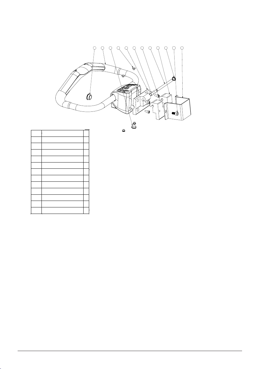
Exploded view and components - EvaDrive, base

310 8 2 7 4 569 1 11
12
REVISION HISTORY
REV.
POS.
DESCRIPTION
DATE
DRAWN BY
ITEM NO.
DOCUMENT NO.
REV.
TITLE
QTY.
1 90003327 01
Hinge outer
1
290003326 01
Hinge inner
1
390003269 00
Handle EvaDrive
1
490003323 01
Hinge axis
1
590003322 00
Washer starlock dome 8x5,7x16
2
690000596 02
MC6S DIN 912 8.8 M6x12 FZB
4
790003328 00
Hinge bushing 8x10x12
3
890003466 00
Cover 7mm grey
4
990003467 00
Cover 16mm grey
1
10 90003468 00
Cover 20mm grey
1
11 90003072 01
Handle Bracket Eva Drive
1
12 90001674 01
Screw MC6S DIN912 8.8 M8x16 fzb
2
D
E
F
C
1
2
3
4
B
A
3
2
1
5
C
D
4
6
7
8
A
B
This drawing and any information or descriptive matter set out hereon are the confidential and copyright property of Handicare
and must not be disclosed, loaned, copied or used for manufacturing, tendering or any other purpose without their written permission.
00C+
SCALE
PROJECTION
MATERIAL SPECIFICATION:
A3
2015-11-05
90005021
EvaDrive Hinge assembly
In work
SIZE
MATERIAL:
TITLE
STATUS
WEIGHT:
SHEET 1 OF 1
CREATED
DATE
NAME
REV.
DWG. NO.
1:2
5
6
E
hc-matfre
310 8 2 7 4 569 1 11
12
REVISION HISTORY
REV.
POS.
DESCRIPTION
DATE
DRAWN BY
ITEM NO.
DOCUMENT NO.
REV.
TITLE
QTY.
1 90003327 01
Hinge outer
1
2 90003326 01
Hinge inner
1
3 90003269 00
Handle EvaDrive
1
4 90003323 01
Hinge axis
1
5 90003322 00
Washer starlock dome 8x5,7x16
2
6 90000596 02
MC6S DIN 912 8.8 M6x12 FZB
4
7 90003328 00
Hinge bushing 8x10x12
3
8 90003466 00
Cover 7mm grey
4
9 90003467 00
Cover 16mm grey
1
10 90003468 00
Cover 20mm grey
1
11 90003072 01
Handle Bracket Eva Drive
1
12 90001674 01
Screw MC6S DIN912 8.8 M8x16 fzb
2
D
E
F
C
1
2
3
4
B
A
3
2
1
5
C
D
4
6
7
8
A
B
This drawing and any information or descriptive matter set out hereon are the confidential and copyright property of Handicare
and must not be disclosed, loaned, copied or used for manufacturing, tendering or any other purpose without their written permission.
00C+
SCALE
PROJECTION
MATERIAL SPECIFICATION:
A3
2015-11-05
90005021
EvaDrive Hinge assembly
In work
SIZE
MATERIAL:
TITLE
STATUS
WEIGHT:
SHEET 1 OF 1
CREATED
DATE
NAME
REV.
DWG. NO.
1:2
5
6
E
hc-matfre
310 8 2 7 4 569 1 11
12
REVISION HISTORY
REV.
POS.
DESCRIPTION
DATE
DRAWN BY
ITEM NO.
DOCUMENT NO.
REV.
TITLE
QTY.
1
90003327 01
Hinge outer
1
2
90003326 01
Hinge inner
1
3
90003269 00
Handle EvaDrive
1
4
90003323 01
Hinge axis
1
5
90003322 00
Washer starlock dome 8x5,7x16
2
6
90000596 02
MC6S DIN 912 8.8 M6x12 FZB
4
7
90003328 00
Hinge bushing 8x10x12
3
8
90003466 00
Cover 7mm grey
4
9
90003467 00
Cover 16mm grey
1
10
90003468 00
Cover 20mm grey
1
11
90003072 01
Handle Bracket Eva Drive
1
12
90001674 01
Screw MC6S DIN912 8.8 M8x16 fzb
2
D
E
F
C
1
2
3
4
B
A
3
2
1
5
C
D
4
6
7
8
A
B
This drawing and any information or descriptive matter set out hereon are the confidential and copyright property of Handicare
and must not be disclosed, loaned, copied or used for manufacturing, tendering or any other purpose without their written permission.
00C+
SCALE
PROJECTION
MATERIAL SPECIFICATION:
A3
2015-11-05
90005021
EvaDrive Hinge assembly
In work
SIZE
MATERIAL:
TITLE
STATUS
WEIGHT:
SHEET 1 OF 1
CREATED
DATE
NAME
REV.
DWG. NO.
1:2
5
6
E
hc-matfre
Exploded view and components - EvaDrive, handle
8SERVICE MANUAL SystemRoMedicTM

9
SERVICE MANUAL
SystemRoMedicTM
2
1
A1
A2
OBC
M1
M2
BATTERY
INH-2
JSM
3
4
PG DRIVES VR2 POWER MODULE CONNECTIONS
JSM
INH-2
A1 A2
OBC
M1
BATTERY
M2
5
6
7
ITEM NO.
DOCUMENT NO.
REV.
TITLE
QTY.
1 90005090 03
EvaDrive actuator cable long
straight mini-fit
1
2 90005089 01
EvaDrive actuator cable short
angled micro-fit
1
3 90005091 01
EvaDrive Emergency Stop Cable
1
4 90005092 01
EvaDrive battery cable
1
5 90003269 01
Eva Drive Handle
1
6 90004467 02
Hubmotor with connector right
1
7 90004466 02
Hubmotor with connector left
1
8 90005192 01
Ferrite filter 742 712 21
3
9 90005191 01
Ferrite filter 742 715 3
2
10 90005190 01
Ferrite filter 742 715 1
3
2
1
A1
A2
OBC
M1
M2
BATTERY
INH-2
JSM
3
4
PG DRIVES VR2 POWER MODULE CONNECTIONS
JSM
INH-2
A1 A2
OBC
M1
BATTERY
M2
5
6
7
ITEM NO.
DOCUMENT NO.
REV.
TITLE
QTY.
1
90005090 03
EvaDrive actuator cable long
straight mini-fit
1
2
90005089 01
EvaDrive actuator cable short
angled micro-fit
1
3
90005091 01
EvaDrive Emergency Stop Cable
1
4
90005092 01
EvaDrive battery cable
1
5
90003269 01
Eva Drive Handle
1
6
90004467 02
Hubmotor with connector right
1
7
90004466 02
Hubmotor with connector left
1
8 90005192 01
Ferrite filter 742 712 21
3
9 90005191 01
Ferrite filter 742 715 3
2
10 90005190 01
Ferrite filter 742 715 1
3
2
1
A1
A2
OBC
M1
M2
BATTERY
INH-2
JSM
3
4
PG DRIVES VR2 POWER MODULE CONNECTIONS
JSM
INH-2
A1 A2
OBC
M1
BATTERY
M2
5
6
7
ITEM NO.
DOCUMENT NO.
REV.
TITLE
QTY.
1 90005090 03
EvaDrive actuator cable long
straight mini-fit
1
2 90005089 01
EvaDrive actuator cable short
angled micro-fit
1
3 90005091 01
EvaDrive Emergency Stop Cable
1
4 90005092 01
EvaDrive battery cable
1
5 90003269 01
Eva Drive Handle
1
6 90004467 02
Hubmotor with connector right
1
7 90004466 02
Hubmotor with connector left
1
8 90005192 01
Ferrite filter 742 712 21
3
9 90005191 01
Ferrite filter 742 715 3
2
10 90005190 01
Ferrite filter 742 715 1
3
Exploded view and components - VR2 and cabels

Spare part list
Art no. Product Unit Components Parts
80100172 Handle EvaDrive 1 pce 1 x Drive handle incl. hinge
assembly
2 x Screws
60900022 Battery EvaDrive 1 pce 1 x Battery
1 x Charger
4 x Charger cable EU, AU,
US/JP, UK
80100174 Cover leg EvaDrive 2 pce 2 x Cover leg EvaDrive
80100175 Cover Eva450Drive 1 set 1 x Cover
1 x Cabel entry
1 x Velcro 100 mm
80100176 Cover Eva600Drive 1 set 1 x Cover
1 x Cabel entry
1 x Velcro 100 mm
80100196 Emergency stop button
EvaDrive
1 pce 1 x Emergency stop button
80100177 Actuator LA30 2-way
335mm Eva450Drive
1 pce 1 x Actuator
4 x Cable ties
2 x M8 lock nut
80100178 Actuator LA30 2-way
478mm Eva600Drive
1 pce 1 x Actuator
4 x Cable ties
2 x M8 lock nut
80100179 Hub motor wheel, right
EvaDrive
1 pce 1 x Wheel
2 x Cable ties
80100180 Hub motor wheel, left
EvaDrive
1 pce 1 x Wheel
2 x Cable ties
80100181 ADM - box EvaDrive 1 pce 4 x Spacer 4,2 x 8 x 15
4 x Screw MF6S
4 x M4 Lock nut
4 x Washer DIN125
80100182 Control box VR2
Eva450Drive
1 pce 1 x Control box VR2
2 x Screw MC6S
2 x Washer DIN125
80100197 Control box VR2
Eva600Drive
1 pce 1 x Control box VR2
2 x Screw MC6S
2 x Washer DIN125
REV.
5
234
32 54
REV.
234
32 54
5
1
2
3
REVISION HISTORY
REV.
POS.
DESCRIPTION
DATE
DRAWN BY
01
Released for manufacturing
2016-12-06
hc-theeli
Item
No.
Part No.
Rev.
Description
Qty.
1 90004212 01
Actuator LA30 2-
way 478mm
(301358-00)
1
290005060 01
Nut ML6M DIN439
ISO4035 M10 fzb
1
390004723 03
Eva drive actuator
stearing pin
1
D
E
F
C
1
2
3
4
B
A
3
2
1
5
C
D
4
6
7
8
A
B
This drawing and any information or descriptive matter set out hereon are the confidential and copyright property of Handicare
and must not be disclosed, loaned, copied or used for manufacturing, tendering or any other purpose without their written permission.
01
SCALE
PROJECTION
MATERIAL SPECIFICATION:
A3
2016-12-07
967.82 g
80100178
Actuator LA30 2-way 478mm Eva600Drive
Released
SIZE
MATERIAL:
TITLE
STATUS
WEIGHT:
SHEET 1 OF 1
CREATED
DATE
NAME
REV.
DWG. NO.
1:2
5
6
E
hc-theeli
1
2
3
REVISION HISTORY
REV.
POS.
DESCRIPTION
DATE
DRAWN BY
01
Released for manufacturing
2016-12-07
hc-theeli
Item No.
Part No.
Rev.
Description
Qty.
1
90003945 01
Actuator LA30 2-way
335mm (301357-00)
1
2
90005060 01 Nut ML6M DIN439
ISO4035 M10 fzb
1
3
90004723 03
Eva drive actuator
stearing pin
1
D
E
F
C
1
2
3
4
B
A
3
2
1
5
C
D
4
6
7
8
A
B
This drawing and any information or descriptive matter set out hereon are the confidential and copyright property of Handicare
and must not be disclosed, loaned, copied or used for manufacturing, tendering or any other purpose without their written permission.
01
SCALE
PROJECTION
MATERIAL SPECIFICATION:
A3
2016-12-07
878.55 g
80100177
Actuator LA30 2-way 335 mm Eva450Drive
Released
SIZE
MATERIAL:
TITLE
STATUS
WEIGHT:
SHEET 1 OF 1
CREATED
DATE
NAME
REV.
DWG. NO.
1:2
5
6
E
hc-theeli
10 SERVICE MANUAL SystemRoMedicTM

11
SERVICE MANUAL
SystemRoMedicTM
Art no. Product Unit Components Parts
80100184 Cable entry EvaDrive 1 set 1 x EvaDrive cable entry top
1 x EvaDrive cable entry front
2 x Screws
80100185 Cable Battery EvaDrive 1 pce 1 x Cable Battery
80100186 Cable actuator LA44
EvaDrive
1 pce 1 x Cable actuator LA44
80100187 Cable actuator LA23
EvaDrive
1 pce 1 x Cable actuator LA23
80100189 Cable Emergency stop
EvaDrive
1 pce 1 x Cable Emergency stop
80100190 Charger Li-Ion EvaDrive 1 pce 1 x Charger Li-Ion EvaDrive
Note: Charger cabel not
included.
80100191 Cable Charger EU
EvaDrive
1 pce 1 x Cable Charger EU
80100192 Cable Charger AU/NZ
EvaDrive
1 pce 1 x Cable Charger AU/NZ
80100193 Cable Charger US/JP
EvaDrive
1 pce 1 x Cable Charger US/JP
80100194 Cable Charger UK
EvaDrive
1 pce 1 x Cable Charger UK
234
32 54
5

Changing of spare parts
80100172 Handle EvaDrive
Set battery switch OFF. Disconnect battery cable. Remove battery. Detach cover. The cover is secured by pads of velcro.
Remove Cable entry. Separate cable entry. Detach connectors from control boxes (VR2 box AND ADM-box) Remove
cable from cover. Note: routing of cables. Remove 2 screws from handle bracket.
Replace Handle including hinge assembly. Replace 2x Screws (K6S M8x16). Adjust handle height. Tighten screws.
Thread cable through cover and routing them to control boxes. Attach connectors to VR2 and ADM-box (see p. 9).
Assemble cable entry and adjust cable positions and length. Note: Cable length adjustment is important in relation to
mast and handle position. Fit cable entry in cover. Reposition the cover and press it into place. Reattach battery and
battery cable. Important! If a new handle is is fitted, an initial calibration must be performed as follows:
- Make sure the handle is not physically loaded in any way (e.g. handset must not be hangin on the handle)
- Start the system by pressing the ON button
- The Snail light starts blinking with double beats
- Allow the system to initiate until the Snail light stops blinking. This may take up to 10 minutes
- Test all basic functions of the drive system. Make sure approximately the same force is needed to initiate
forwards and backwards motion. If not, perform a manual calibration of the system (se page 10 in the user
manual).
60900022 Battery Eva Drive
Set battery switch OFF. Detach battery cable. Slide the old battery upwards. If necessary adjust handle position.
Replace with new battery. Gently slide battery back into place. Reattach battery cable and switch ON. Readjust handle
position.
80100174 Cover leg EvaDrive
Replace cover leg by pressing it into back of leg profile, use LocTite715 glue to fasten the profile.
80100175/176 Cover Eva450Drive/ Cover Eva600Drive
Set battery switch OFF. Disconnect battery cable. Detach cover. The cover is secured by pads of velcro. Remove the
velcro from base. Cut the new velcro into eight pieces. Attach the bits of velcro to the same place on the base as the old
ones. Keep them together with their ”twins”. Detach Cable entry. Remove the emergency stop button by unscrewing
the plastic retainer on the inside of the cover. Note routing of cables. Remove and replace cover.
Route cables and fit cable entry into cover. Re-connect cables to control boxes, 4x to VR2 and 1x to ADM-box (see p.
9). Remove the glue cover from the velcro. Secure the cover by pressing it into place. Re attach battery cable and switch
ON.
80100196 Emergency stop button EvaDrive
Set battery switch to OFF. Disconnect battery cable. Detach cover. The cover is secured by pads of velcro. Detach Cable
entry. Remove the emergency stop button by unscrewing the plastic retainer on the inside of the cover. Note routing of
cables. Detach emergency stop cable connector from control box VR2. Disconnect cables from emergency stop button
by unscrewing the cable clamp screws. NOTE! numbers of connection points (no 21, 22). Remove and replace emer-
gency stop button with the new one, re-attach Emergency stop cables to the emergency stop button. Route cables and
fit cable entry into cover. Re-connect cables to control boxes, 4x to VR2 and 1x to ADM-box (see p. 9). Secure the cover
by pressing it into place. Re attach battery cable and switch ON.
12 SERVICE MANUAL SystemRoMedicTM

13
SERVICE MANUAL
SystemRoMedicTM
Changing of spare parts
80100177/178 Actuator LA30 2-way 335mm Eva450Drive/ Actuator LA30 2-way 478mm Eva600Drive
Position the wheels in forward position. Set battery switch OFF. Disconnect battery cable. Detach cover. The cover is
secured by pads of velcro. Disconnect the connectors to the actuator. Note: routing of cables. Cut 4x cable ties securing
the HUB-motor cables. Unscrew the 2 shoulder bolts holding the actuator ends. Slide the actuator out backwards.
Loosen the nut, securing the Actuator stearing pin. Slide the new actuator in place. Before reattaching the 2 shoulder
bolts to the actuator ends, make sure that the actuator pistons are in its most inward position by turning the pistons
clock-wise. Reattach shoulder bolts with new M8 lock nuts. Secure HUB-motor cables with 4x cable ties.
Note: cable tension. Route the actuator cable and reconnect the connectors. Reattach cover. Secure the cover by
pressing it into place. Re attach battery and battery cable and switch ON. Test wheel turning function. Check that the
wheels are straight forward and parallel in forward drive mode. If not follow the instructions in chapter Adjusting Toe-in/
Toe-out (see p. 15).
80100179/180 Hub motor wheel, right EvaDrive/ Hub motor wheel, left EvaDrive
Position the wheels in forward position. Set battery switch OFF. Disconnect battery cable. Detach cover. The cover is
secured by pads of velcro. Disconnect the connectors to the HUB motor. Note: routing of cables. Cut the cable ties
securing the HUB-motor cable. Unscrew the M18 lock nut. Remove the spacer. Tap the wheel shaft to remove the
HUB-motor wheel. Replace the HUB motor wheel Note: Replace and reposition the parallel key in the keyway. Fit the
spacer and tighten a new lock nut firmly. Rout the cable and reattach the connector to the HUB-motor. Secure
HUB-motor cable with cable ties. Note: cable tension. Reattach cover. Secure the cover by pressing it into place.
Re-attach battery and battery cable and switch ON. Test the drive function by maneuvering the lift.
80100181 ADM - box EvaDrive
Position the wheels in forward position. Set battery switch OFF. Disconnect battery cable. Detach cover. The cover is
secured by pads of velcro. Disconnect the connectors to the wheel-actuator LA30. Note: routing of cables. For easier
access, tilt the lift on its side. Disconnect the connector from the ADM-box to the handle.
Loosen the VR2-control box by loosening one screw on one side and removing the other. Remove and replace the
ADM-box. Using the new components. Reattach the VR2-control box. Reconnect the handle connector to the
ADM-box. Tilt the lift back on its wheels. Reconnect the wheel-actuator LA30. Note: routing of cables. Reattach cover.
Secure the cover by pressing it into place. Re attach battery and battery cable and switch ON. Test the drive function by
turning the back wheels.
80100182/ 80100197 Control box VR2 Eva450Drive/ Control box VR2 Eva600Drive
Position the wheels in forward position. Set battery switch OFF. Disconnect battery cable. Detach cover. The cover is
secured by pads of velcro. Disconnect all of the connectors to the VR2 Control box. Note: connector positions. Remove
and replace the VR2 control box. Using the new components. Re-connect all of the cables to control box (see p. 9).
Secure the cover by pressing it into place. Re attach battery and battery cable and switch ON.
80100184 Cable entry EvaDrive
Detach cover. The cover is secured by pads of velcro. Remove Cable entry. Separate cable entry top and front and
replace with new ones. Fit cable entry in cover. Reposition the cover and press it into place.

Changing of spare parts
80100185 Cable Battery EvaDrive
Set battery switch OFF. Disconnect battery cable. Detach cover. The cover is secured by pads of velcro. Remove Cable
entry. Separate cable entry. Detach battery connector from control box VR2. Remove VR2 Control box. Remove cable
from cover and replace with new one. Note: routing of cable.
Assemble cable entry and adjust cable positions and length. Note: Cable length adjustment is important in relation to
mast position. Fit cable entry in cover. Reposition the cover and press it into place. Re attach battery cable and switch
ON. Check cable length adjustment.
80100187 Cable actuator LA23 EvaDrive
Set battery switch OFF. Disconnect battery. Detach cover. The cover is secured by pads of velcro. Detach LA23 actuator
cable connector from control box VR2. For easier access, tilt the lift on its side and detach the LA23 actuator in one end.
Disconnect LA23 actuator cable from actuator and reconnect new cable. Reattach the actuator and tilt the lift back on
its wheels. Connect the LA23 actuator cable to the control box VR2 (see p. 9). Reposition the cover and press it into
place.
Reattach battery cable and switch ON.
80100189 Cable Emergency stop EvaDrive
Set battery switch OFF. Disconnect battery. Detach cover. The cover is secured by pads of velcro. Detach emergency
stop cable connector from control box VR2 and disconnect from emergency stop button. Remove and replace
emergency stop cable (in connection points 21, 22). Reposition the cover and press it into place. Re attach battery cable
and switch ON.
80100190 Charger Li-Ion EvaDrive
Choose the correct charger plug to fit the wall socket. Connect the cable to the battery and plug the charger into a wall
socket.
80100191/192/193/194 Cable Charger EU EvaDrive/ AU/NZ EvaDrive/ US/JP EvaDrive/ UK EvaDrive
Connect the charger cable to the charger.
80100186 Cable actuator LA44 EvaDrive
Set battery switch OFF. Disconnect battery. Disconnect LA44 actuator cable from actuator.
Detach cover. The cover is secured by pads of velcro. Remove Cable entry. Separate cable entry.
Detach LA44 actuator cable connector from control box VR2. Remove cable from cover and
replace with new one. Note: routing of cable.
Assemble cable entry and adjust cable positions and length. Note: Cable length adjustment is
important in relation to mast position. Fit cable entry in cover. Reposition the cover and press it
into place. Re attach battery cable and switch ON. Check cable length adjustment.
14 SERVICE MANUAL SystemRoMedicTM

15
SERVICE MANUAL
SystemRoMedicTM
Adjusting Toe-in/Toe-out
1. Remove the cover by gently pulling it
at the four Velcro points
2. Loosen all four screws securing ONE
of the brackets to the center beam, but
do not remove them.
3. Loosen all four screws connecting the
center plate with the brackets, but do
not remove them
4. Straighten one of the wheels by hand.
Note that the loose bracket moves
relative to the center beam.
5. With the wheel straight, tighten the two center plate screws.
6. Straighten the other wheel by hand.
7. Tighten the two remaining center plate screws.
8. Tighten all four screws loosened in (2).

Base:
A Drive unit
Check:
B Rear wheel
C Brakes
D Emergency stop
Handle:
E Inspect the handle
Check:
F Grip
G Buttons
G Drive forward
G Drive backwards
G Wheel turning
Cabels:
Weare and damage
Inside the unit:
Cables
Weare and damage
Noise
Accessories:
Documentation:
Instructions /User manuals
Lift type: Contract no:
s/n: Name:
Version: Address:
Prod. year:
Sling bar id.: Situation of use: Home Institution Other
Comments: 1. Attention 2. Correct 3. Do not use!
Periodic inspection - protocol
Date:
Load test weight: Serviced by:
In accordance with ISO 10535:2006 Annex B-Periodic inspection

17
SERVICE MANUAL
SystemRoMedicTM
A
B
D
C
E
F
G
Description for periodic inspection

Periodic inspection - instruction
Check the Drive unit
-Check the drive unit for visible damage to the surfaces, finish, etc.
-Check the drive unit for loose bolts and nuts. tighten if necessary.
Rear Wheels
-On a flat surface, check that the wheels are in contact with the surface when the legs are together and fully spread.
-Check for abnormal wear, dirt and hair. Clean if necessary.
Brakes
-Check the brake function by engaging the brakes and pushing the lift manually without touching the handle. The lift
should not move.
-Check the automatic brake release by engaging the brakes and drive the unit forwards and backwards using the
handle. a click sound will be heard. The lift should move.
Emergency stop
-Check emergency stop function by pressing the emergency stop button and then try to drive backwards and forwards.
Nothing should happen. then press the up and down button. If nothing happens the emergency stop buppen functions
properly.
Inspect the handle
-Check screws, nuts, bolts etc.
-Check for damage and ware.
Grip
-Drive the unit forward, regular speed, 10 meters.
-Drive the unit backwards, regular speed, 10 meters.
-Check the steering, drive the unit forward and back and verify that it turns right and left when pushing the handle.
Buttons
-Check the buttons by pressing them in turn and observing respective function.
-Turn the wheels to 45 degrees and drive left and right
-Turn the wheels 90 degrees and drive sideways. Check that the light on the handle is lit.
-Turn the wheels to starting position. Check that the light is turned off.
Cables
-Check for weares and damages.
Inside the unit
-Check for weares and damages.
-Check for dirt and dust.
-Listen for abnormal noise while operating the unit.
18 SERVICE MANUAL SystemRoMedicTM

19
SERVICE MANUAL
SystemRoMedicTM
Maintenance
The lift must undergo thorough inspection at least once per year or when the service indicator light is turned on after
2000 lifts (Whichever comes first). Inspection must be performed by authorized personnel and in accordance with
Handicare’s service manual.
Repairs and maintenance may only be done by authorized personnel using original spare parts.
Used batteries are to be left at the nearest recycling station. Used batteries can also be returned to
Handicare or a Handicare dealer for recycling.
+50 ºC
-10 ºC
Cleaning/disinfection
If necessary, clean the lift with warm water or a soap solution and check that the castors are free from dirt and hair. Do
not use cleaning agents containing phenol or chlorine, as this could damage the aluminium and the plastic materials.
If disinfection is needed, 70 % ethanol, 45 % isopropanol or similar should be used. Disinfect the parts that come in
contact with a user before the lift is used for the next user.
Storage and transportation
If the lift is not to be used for some time or e.g., during transport, we recommend that the emergency stop button be
pressed in. The lift should be transported and stored in -10 ° C to + 50 ° C and in normal humidity, 30% -75 %. The air
pressure should be between 700 and 1060 hPa. Let the lift reach room temperature before the batteries are charged or
the lift is used.
Service agreements
Handicare offers service agreements for maintenance and regular testing of your lift unit. Contact your local Handicare
representative.
106 kPa
70 kPa
75%
30%
1060 hPa
700 hPa
+50 °C
-10 °C
75%
30%

Medical Device Class I. The product complies with the requirements of the Medical Devices Directive 93/42/EEC.
Maximum speed (normal) Forward: 4.3 mph / 7 km/h, Backwards: 2.1 mph / 3,5 km/h
Maximum speed (low speed ) 2.1 mph / 3,5 km/h
Batteries 24V, 17,6 Ah Li-Ion
Charger Modiary MDA10129402000. Output: DC 29, 40 V, 2.0 A
AC power input cable HD3VV-F 3G0,75mm². TCA090812EA. Length 59 inch, 1500 mm
Motor cover Flame-resistant ABS plastic
Intermittent operation Op 10/90, active op. max. 2 min. Out of a time of 100, active time must be less than
10, though not more than 2 min.
Nav motor 24V DC Mono Shaft, 180 W
Material Aluminium/steel
Emergency lowering Manual
Castors 8 inch, 203 mm
IP class IP X4*
Weight Eva450Drive: 127.87 lbs, 58 kg
Eva600Drive: 141.1 lbs, 64 kg
Weight (heaviest part) Eva450Drive: 97 lbs, 44 kg
Eva600Drive: 110.2 lbs, 50 kg
Turning diameter Eva450Drive: 54 inch/ 1340 mm
Eva600Drive: 61.8 inch/ 1570 mm
Expected service life 10 years
Pressure control panel 4 N
Clearance 1.1 inch, 28 mm
*IP X4: Splashing of water, Water splashing against the enclosure from any direction shall have no harmful effect.
(Test duration: 5 minutes Water volume: 10 litres per minute Pressure: 50–150 kPa)
Technical information
20 SERVICE MANUAL SystemRoMedicTM
Other manuals for SystemRoMedic EvaDrive
2
Table of contents
Other Handicare Lifting System manuals

Handicare
Handicare FREECURVE Basic User manual

Handicare
Handicare SystemRoMedic EvaDrive450 User manual

Handicare
Handicare A-450 User manual

Handicare
Handicare SystemRomedic RiseBasic300M User manual

Handicare
Handicare PRISM MEDICAL P600 User manual

Handicare
Handicare MINIVATOR 2000 User manual

Handicare
Handicare A-450 User manual

Handicare
Handicare SystemRoMedic BariVest XXXL User manual

Handicare
Handicare Eva400 User manual

Handicare
Handicare SystemRoMedic Carina350EM User manual