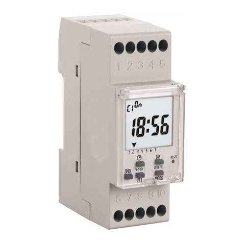
HANYOUNG NUX MA4N User manual

Analog
Multi Timer
MA4N
Thank you for purchasing HANYOUNG NUX CO,.Ltd.Product.
Please check whether the prouduct you purchased is the exactly
same as you ordered. Before using product, please read instruction
maunal carefully.
1381-3, Juan-Dong, Nam-Gu Incheon, Korea
TEL: (82-32)876-4697 FAX:(82-32)876-4696
Safety Information
Before you use, read safety precautions carefully, and use this product properly.
The precautions described in this manual contain important contents related with
safety; therefore, please follow the instructions accordingly. The precautions are
composed of DANGER, WARNING and CAUTION.
There is a danger of occurring electric shock in the input/output terminals so please
never let your body or conductive substance is touched.
1. This product does not contain an electric switch or fuse, so the user needs to
install a separate electric switch or fuse externally. (Fuse rating: 250V 0.5A)
2. To prevent defection or malfunction of this product, supply proper power voltage
in accordance with the rating.
3. To prevent electric shock or malfunction of product, do not supply the power
until the wiring is completed.
4. Since this product is not designed with explosion-protective structure, do not
use it any place with flammable or explosive gas.
5. Do not decompose, modify, revise or repair this product. This may be a cause
of malfunction, electric shock or fire.
6. Reassemble this product while the power is OFF. Otherwise, it may be a cause
of malfunction or electric shock.
7. If you use the product with methods other than specified by the manufacturer,
there may be bodily injuries or property damages.
8. Due to the danger of electric shock, use this product installed onto a panel while
an electric current is applied.
1. The contents of this manual may be changed without prior notification.
2. Before using the product you purchased, make sure that it is exactly what you
ordered.
3. Make sure that there is no damage or abnormality of the product during delivery.
4. Do not use this product at any place with corrosive (especially noxious gas or
ammonia) or flammable gas.
5. Do not use this product at any place with direct vibration or impact.
6. Do not use this product at any place with liquid, oil, medical substances, dust,
salt or iron contents. (Use at Pollution level 1 or 2)
7. Do not polish this product with substances such as alcohol or benzene.
8. Do not use this product at any place with a large inductive difficulty or occurring
static electricity or magnetic noise.
9. Do not use this product at any place with possible thermal accumulation due to
direct sunlight or heat radiation.
10. Install this product at place under 2,000m in altitude.
11. When the product gets wet, the inspection is essential because there is a
danger of electric leakage or fire.
12. If there is excessive noise from the power supply, using insulating transformer
or noise filter is recommended. The noise filter must be attached to a panel
which is already connected to a ground and the wire between the filter output
and power supply terminal must be as short as possible.
13.If puttig power cables closely together then It is effective against noise.
14.Do not connect anything to the unused terminals.
15.After checking the polarity of terminal, connect wires at the correct position.
16.When this product is connected to a panel, use a circuit breaker or switch
approved with IEC947-1 or IEC947-3.
17.Install the circuit breaker or switch at near place for convenient use.
18.Write down on a label that if the circuit breaker or switch is operating then the
power will be disconnected since the circuit breaker or switch is installed.
19.For the continuous and safe use of this product, the periodical maintenance is
recommended.
20.Some parts of this product have limited life span, and others are changed by
their usage.
21.The warranty period for this product including parts is one year if this product is
properly used.
DANGER
WARNING
CAUTION
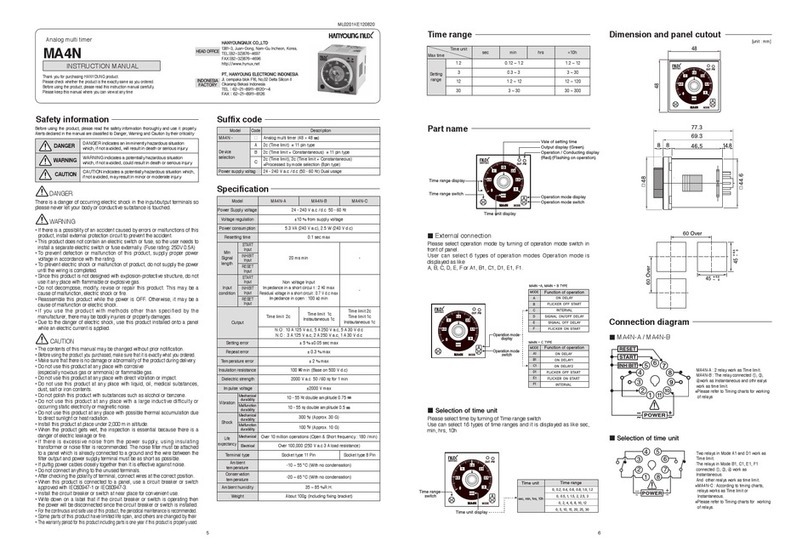
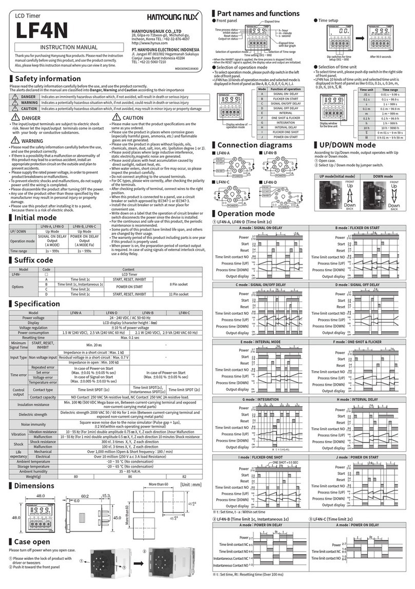
Names and functions of respective parts
Selection of operation mode
Please select operation mode by turning of operation mode switch in front of panel.
User can select 6 types of operation modes Operation mode is displayed as like
A, B, C, D, E, F or A1, B1, C1, D1, E1, F1.
Selection of time unit
Please select time by turning of Time range switch
Use can select 16 types of time ranges and it is displayed as like sec, min, hrs, 10h
INSTRUCTION MANUAL
HEAD OFFICE
All manuals and user guides at all-guides.com
all-guides.com

Time range
Dimensions
Panel cutout
Connections
Specifications
sec min hrs 10h
1. 2
3
12
30
0.12 ~ 1.2
0.3 ~ 3
1.2 ~ 12
3 ~ 30
1.2 ~ 12
3 ~ 30
12 ~ 120
30 ~ 300
Setting range
Max. time
Time unit
Time Limit 1c
Instautaneous 1c
Time Limit 2c
Time Limit 2c
Time Limit 1c
Instautaneous 1c
24 - 240 V a.c / d.c 50 - 60 Hz
10 % from supply voltage
5.3 VA (240 V a.c), 2.5 W (240 V d.c)
Max. 0.1 sec
Min. 20 ms
Max. 5 % 0.05 sec
N.O: 10 A 125 V a.c, 5 A 250 V a.c, 5 A 30 V d.c
N.C: 3 A 125 V a.c, 2 A 250 V a.c, 1A 30 V d.c
Max. 0.3 %
Max. 2 %
Min. 100 MΩ(Base on 500 V d.c)
2000 V a.c 50 / 60 Hz for 1 min.
2000 V Max.
10 - 55 Hz double amplitude 0.75 mm
10 - 55 Hz double amplitude 0.5 mm
300 Approx. 30 G)
100 Approx. 10 G)
Over 10 million operations (Open & Short frequency : 180 / min)
Over 100,000 (250V a.c 3 A load resistance)
Socket type 11 Pin Socket type 8 Pin
-10 ~ 55 No condensation)
-20 ~ 65 No condensation)
35 ~ 85 %R.H.
About 100g (Including fixing bracket)
Non voltage Input
Impedance in a short circui t: Max. 2
Residual voltage in a short circuit:
Max. 0.7 V d.c
Impedance in open: Min. 100
MA4N-A MA4N-B MA4N-C
MinSignal
length
Input
condition
Vibration
Shock
Life
expectancy
START Input
START Input
INHIBIT Input
INHIBIT Input
RESET Input
RESET Input
Output
Mechanical
durability
Malfunction
durability
Mechanical
durability
Malfunction
durability
Mechanical
Electrical
M o d e l
Supply voltage
Voltage regulation
Power consumption
Resetting time
Setting error
Repeat error
Temperature error
Insulation resistance
Dielectric strength
Impulse voltage
Terminal type
Operation ambient
temperature
Conservation temperature
Operation ambient humidity
Weight
(unit : mm)
(unit : mm)
MA4N-A : 2 relay work as Time limit.
MA4N-B : The relay connected , ,
work as Instantaneous and
othr ealys work as time limit.
Please refer to Timing charts for
working of relays
Two relays in Mode A1 and D1 work
as Time limit.
The relays in Mode B1, C1, E1, F1
connected , , work as Instantaneous.
And other realys work as time limit.
MA4N-C : According to timing charts,
relays works as Time limit or
Instantaneous.
Please refer to Timing charts for working
of relays.
All manuals and user guides at all-guides.com

Timing charts (MA4N-A, MA4N-B)
A MODE: ON DELAY
B MODE: FLICKER OFF START
C MODE: INTERVAL
D MODE: SIGNAL ON / OFF DELAY
E MODE: SIGNAL OFF DELAY
F MODE: FLICKER ON START
Power
Start
Reset
Operation / Conducting display LED
Time-Limit contact N.C
Time-Limit contact N.O
Power
Start
Reset
Operation / Conducting display LED
Time-Limit contact N.C
Time-Limit contact N.O
Power
Start
Reset
Operation / Conducting display LED
Time-Limit contact N.C
Time-Limit contact N.O
Power
Start
Reset
Operation / Conducting display LED
Time-Limit contact N.C
Time-Limit contact N.O
Power
Start
Reset
Operation / Conducting display LED
Time-Limit contact N.C
Time-Limit contact N.O
Power
Start
Reset
Operation / Conducting display LED
Time-Limit contact N.C
Time-Limit contact N.O
MA4N-A : Output – Time limit 2c MA4N-B : Output – Instantaneous 1c, Time limit 1c
All manuals and user guides at all-guides.com

Timing charts (MA4N-C)
A1 MODE : ON DELAY
B1 MODE : ON DELAY 1 (One-shot output)
C1 MODE : ON DELAY2
D1 MODE : FLICKER OFF START
E1 MODE : FLICKER ON START
F1 MODE : INTERVAL
Power
Time-Limit output operation display LED
Operation / Conducting display LED
Time-Limit contact N.C
Time-Limit contact N.O
Power
Time-Limit output operation display LED
Operation / Conducting display LED
Time-Limit contact N.C
Time-Limit contact N.O
Power
Time-Limit output operation display LED
Operation / Conducting display LED
The Output width of one shot is fixed by 0.5 second
Time-Limit contact N.C
Time-Limit contact N.O
Instantaneous contact N.C
Instantaneous contact N.O
Power
Time-Limit output operation display LED
Operation / Conducting display LED
Time-Limit contact N.C
Time-Limit contact N.O
Instantaneous contact N.C
Instantaneous contact N.O
Power
Time-Limit output operation display LED
Operation / Conducting display LED
Time-Limit contact N.C
Time-Limit contact N.O
Instantaneous contact N.C
Instantaneous contact N.O
Power
Time-Limit output operation display LED
Operation / Conducting display LED
We suggest over 100 ms of Min. setting time for D1, E1 output mode because excessive short setting time may cause of malfunction
Time-Limit contact N.C
Time-Limit contact N.O
Instantaneous contact N.C
Instantaneous contact N.O
t: Setting time, t-a: Within setting time, Rt: Resetting time
All manuals and user guides at all-guides.com
Other HANYOUNG NUX Timer manuals

HANYOUNG NUX
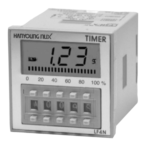
HANYOUNG NUX LF4N User manual

HANYOUNG NUX
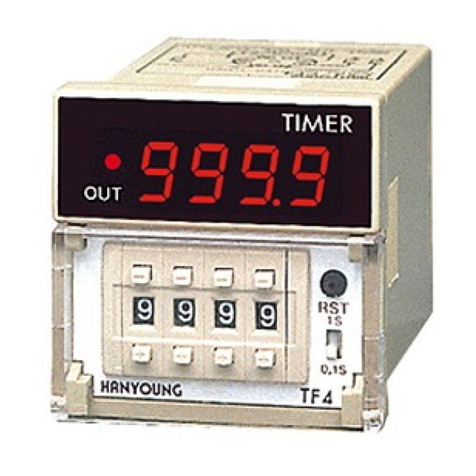
HANYOUNG NUX TF4 User manual

HANYOUNG NUX
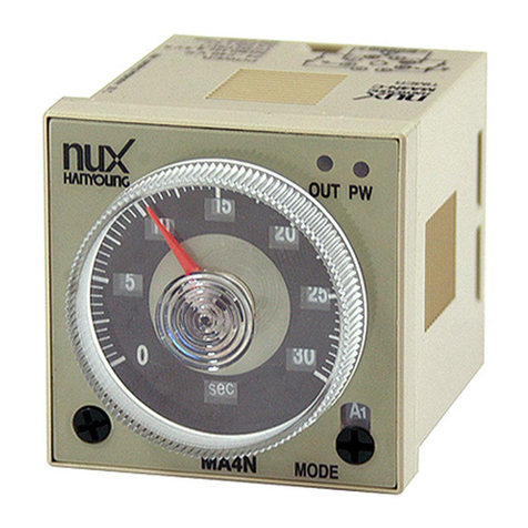
HANYOUNG NUX MA4N-A User manual

HANYOUNG NUX
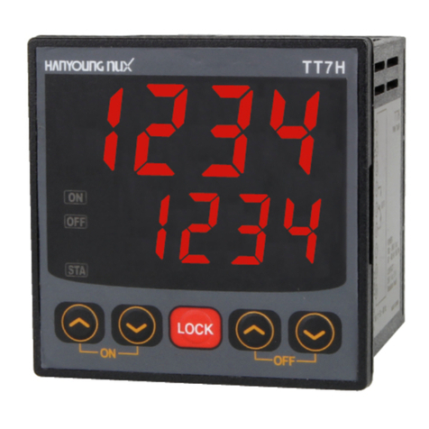
HANYOUNG NUX TT7H User manual

HANYOUNG NUX
HANYOUNG NUX LT4 Series User manual

HANYOUNG NUX
HANYOUNG NUX TF4A User manual

HANYOUNG NUX
HANYOUNG NUX MA4N-A User manual

HANYOUNG NUX
HANYOUNG NUX T48A User manual

HANYOUNG NUX
HANYOUNG NUX TF62A User manual

HANYOUNG NUX
HANYOUNG NUX TF2 User manual