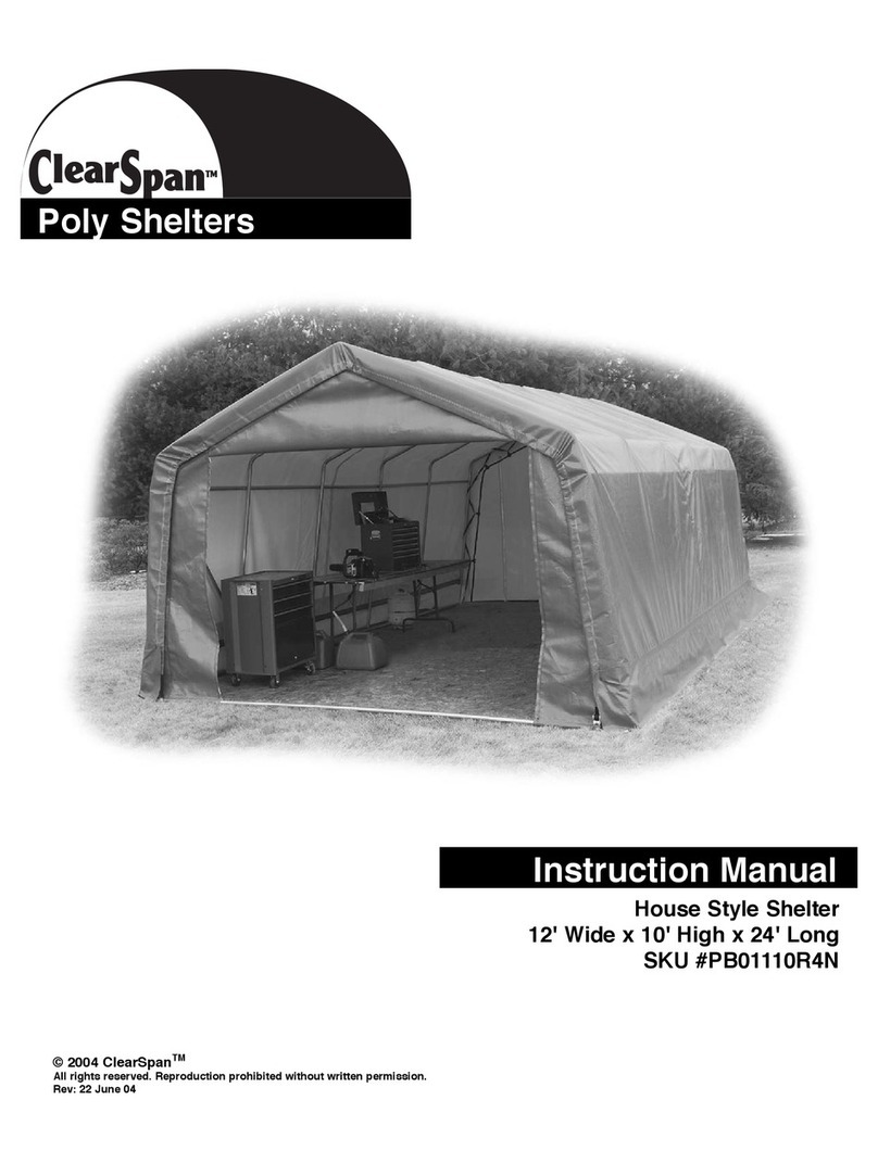
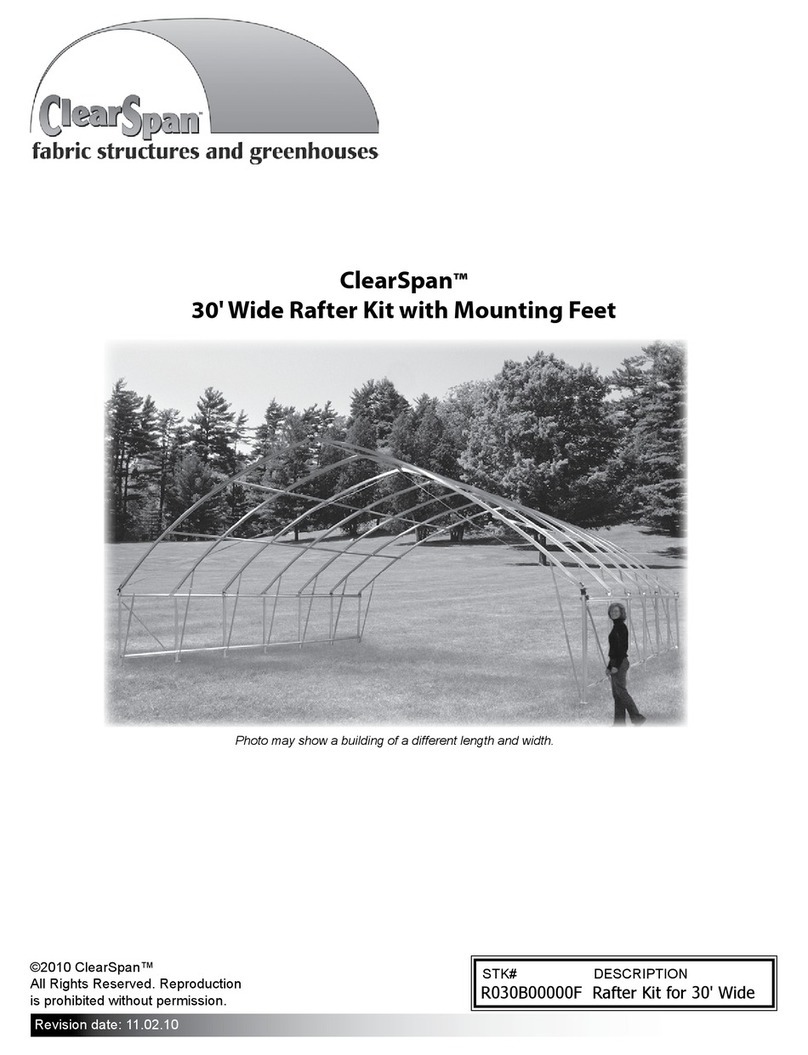
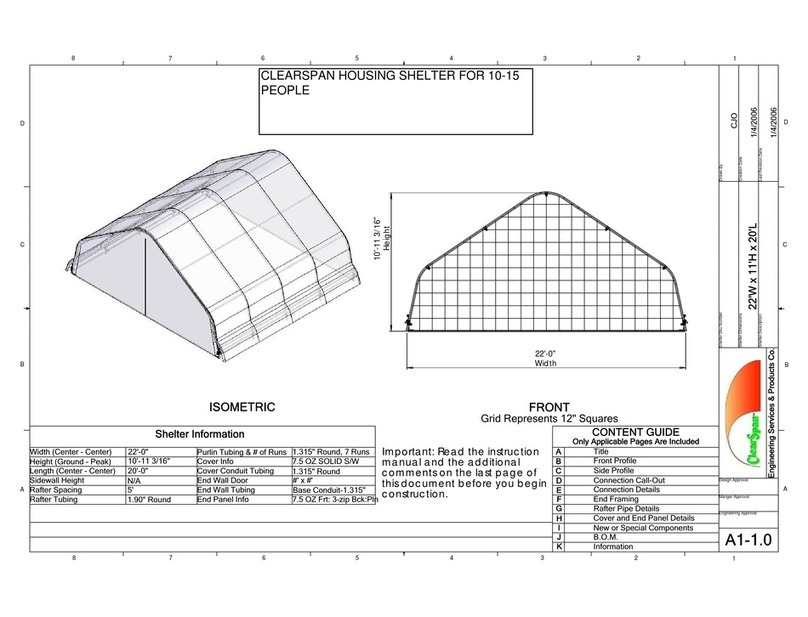
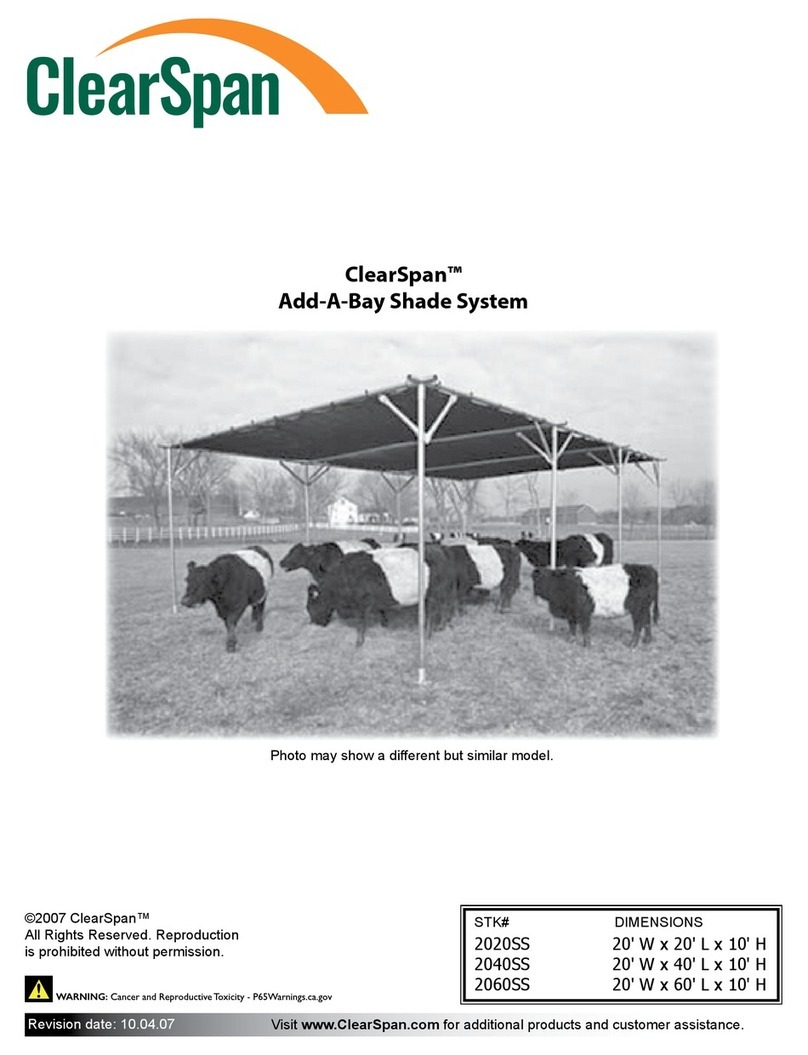
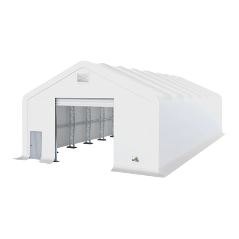
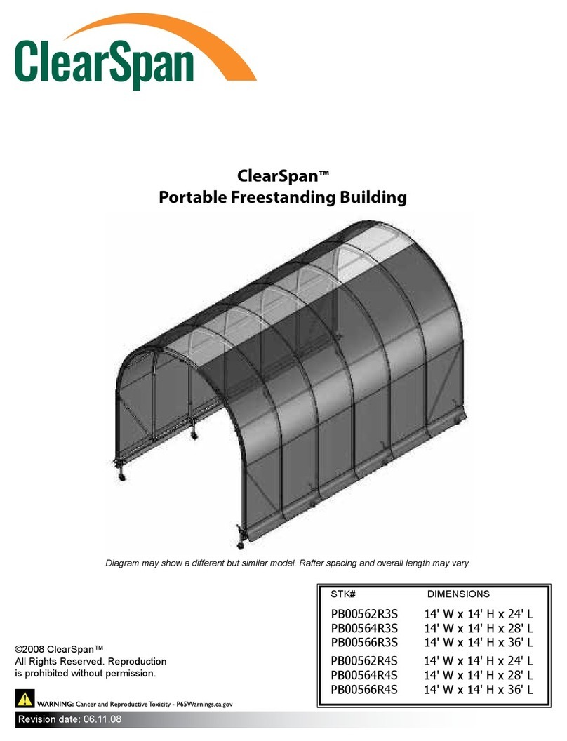
ClearSpan 103476 User manual

Instruction Manual
Poly Shelters
Portable Greenhouse
10' Wide x 20' Long
SKU #103476
© 2004 ClearSpanTM
All rights reserved. Reproduction prohibited without written permission.
Rev: 18 Mar 04
Note: Photo may be of a different but similar model

Introduction
Thank you for purchasing the ClearSpanTM Poly Shelter. We appreciate your patronage. We hope
you enjoy building and utilizing your shelter. Please read this entire instruction manual before
starting to assemble your shelter. If you require assistance during the construction process you may
call us at 1-800-245-9881.
A Word About Safety
Just as we want you to be pleased with your assembled shelter, we donʼt want you to get hurt in the
process of building it! Our suggestions include the following:
• Wear eye protection when drilling and power-screwing.
• Wear head protection when working with/under heavy parts including metal tubing.
• Wear gloves when handling metal tubing due to sharp or rough ends.
• Use a portable GFCI when working with corded power tools.
• Never erect a shelter directly under power lines.
• Be careful not to drive anchors into buried power cables.
• Do not climb on the shelter or its frame. It is not designed to support human weight.
• If the shelter is enclosed, provide proper and adequate ventilation.
• Do not store hazardous materials in the shelter without proper ventilation and precautions.
• If both ends are covered, provide proper ingress and egress to prevent entrapment.
• Do not occupy the shelter during very high winds, hurricanes, or tornadoes.
• If shelter is moved after construction, inspect shelter thoroughly before reuse.
• Use common sense at all times.
Suggested Tools
Before you start to build your shelter you should assemble the following tools:
• Tape Measure
• Fine Point Marker
• Screwdriver or Electric Drill/Driver (cordless preferred)
• Hacksaw
• Adjustable Wrench or Socket Set
• Step ladder tall enough to safely work at the height of your shelter
Page 2
Selecting a Location
It is important to select a proper location for your poly shelter. While the location may have been
predetermined before you even ordered your shelter, you may want to “improve” the location before
starting the assembly process.
One of the most important considerations is that the location should be level. If it is not, the shelterʼs
frame will not assemble or sit properly. If your location is not level, you should consider grading it
before building on it. Another alternative is to provide footings which are level to support the shelter.
These could be pressure-treated posts, precast concrete blocks, or poured in place footings.
Drainage is another important consideration. Rain flowing off your shelter should have a natural path
to flow away from the shelter and not under or into it.
Section A - Unpack & Identify Parts
Step 1: Before you begin to assemble your shelter you should first unpack the contents of your
shipment. During this process you will both verify that you have all the parts required to build
your shelter and learn what all of the various parts look like.
Tip: We recommend you start by laying out the contents of your shipment in an orderly fashion
as shown in the photograph below. Note that your parts may look different from those shown.
The contents of the Bill of Material for your shelter will depend on the size of the shelter ordered.
Please refer to the Bill of Material that came with your shelter.
Step 2: Carefully go through the bill of material and verify that you have all the required parts.
Tip: It is not necessary to open the plastic bags and count all of the fasteners at this time.
Likewise, it is not necessary to unfold your covers except to verify that you have the correct
end panels as ordered.
Page 3

Parts Identification
Note: Illustrations are not to scale.
Page 4
Pipe (only swaged is shown)
Self-Drilling Screw
3-Way Coupler
Corner Coupler
Cover
Pipe Strap
Fabric Clip
U-Bolts
Anchor
Plain End Strap
Strap Ratchet
Zippered End Panels
(1 with wide door, 1 with man door)
4-Way Coupler Bottom “T”

Section B - Assembly
68"
Pipe
10'
10'
52"
Pipe
10'
4 Way
Coupler
3 Way
Coupler
Typical Roof Frame Parts Laid Out
Step 1: Assemble (6) 10' sections of ridge pipe by slipping a swedged 52" pipe into a 68" pipe.
Step 2: Arrange the roof pipes on the ground adjacent to the correct 3-Way and 4-Way couplers.
68"
52"
68"
Page 5

Step 3: Connect the pipes and couplers as illustrated.
Step 4: Create (2) 1/2" PVC pipes by connecting 3 sections for each. Slip a PVC cap onto each
end. Place the first pipe underneath the outside purlin. Bend pipe over and down from top ridge
towards other outside purlin. Place pipe underneath purlin. Center pipe on frame between two
rafters as shown. Repeat the above procedure for placement of the second pipe.
Page 6

Step 5: Fasten both pipes with two 1/2" pipes straps each using self-drilling pan head screws; no
pilot hole is needed. Trim excess PVC pipe.
Step 6: Lift one side of roof and slide in the 68" leg poles. Then lift the other side and insert the
remaining leg poles. (Note illustration below may not match your frame exactly.)
Legs
Step 7: Create pipe sections as diagram illustrates.Connect these sections with couplers as
shown. Slip a leg pole into each bottom coupler.
52" 52"
27" 68"
90° Corner Coupler
Bottom Tee
Leg
Pole
Page 7

Section C - Anchor Frame
Step 1: Screw an auger earth anchor into the ground near each leg. Anchors must be placed close
enough to the bottom frame to ensure a connection with the U-clamps.
Step 2: Slip the U-clamp around the bottom frame. Place one of the legs of the U-clamp through the
eye of the anchor. Install U-clamp plate and bolts and tighten.
Page 8

Section F - Install End Panels
DO NOT INSTALL END PANELS ON A WINDY DAY AS DAMAGE TO THEM MAY RESULT!
Step 1: Locate the end panels. Notice that one end panel has a narrow “man door” and the other
has a wider multi-purpose door. Decide where you will use each end panel before proceeding.
Then, install each end panel using the steps that follow.
If the corners of your end panel have not been cut out, follow steps 2 and 3 below to do so:
Step 2: Position the end panel hem next to the conduit at the end of your shelter. Note where the
corner couplers are in relation to the end panel hem.
Step 3: With scissors, trim the corner of the end panel hem on the dotted line shown below so the
corner coupler will be exposed when the conduit is placed inside the hem. Repeat at the other
end of the end panel.
Step 4: Remove one end of the end conduit from the corner coupler and slide the hem of the end
panel over the conduit. Replace the connector you removed. Do not put the hem of the middle
door section over the conduit, just the sections to either side of the door.
Page 9

Step 5: While standing inside the shelter, start at the peak of the end rafter and pull the end panel
over the top of the rafter so the material edge is on the inside of the rafter.
Step 6: Secure the panel in place at the top center with a fabric clip.
Step 7: Move outward in both directions, placing one fabric clip every 24."
Step 8: Your end panels may have been shipped as untrimmed rectangular pieces. If so, you may
use scissors to trim the excess end panel material inside the shelter to an inch or two past the
fabric clips as shown in the illustration above.
Page 10

Section G - Install Main Cover
Step 1: Fasten a ratchet to the end conduit with a Tek screw in the bottom hole of the ratchet. The
ratchet should be about 6" in from the end of the conduit. Repeat this step in all four corners.
End Ratchet Installed Side Ratchet Installed
Note: corner coupler shown above may differ from that supplied with this model
Step 2: Inside the shelter, use a Tek screw to attach a side ratchet to each corner connector as
shown above. Also install a ratchet on one side of the two bottom “T” connectors. These
ratchets should be installed on the sides of the shelter. You should have a total of (6) side
ratchets installed, (3) on each side.
Step 3: Make up a pair of cover conduits each the length of your shelter. Start each with an
unswaged section and add swaged sections to arrive at the correct length.
Warning: DO NOT INSTALL COVER ON A WINDY DAY AS DAMAGE TO IT MAY RESULT!
Step 4: Unpack the main cover and unfold it completely with the inside surface facing up.
Step 5: Locate the ends with strapping and line them up with the front and back of the shelter.
Step 6: Slide cover conduits into hem openings as shown in the next illustration.
Page 11

Step 7: To pull the cover over the frame, attach ropes to the both ends of the cover conduit. Wrap
the rope around the conduit a few times as shown below to prevent the rope from slipping off
accidentally.
Step 8: Then pull the ropes over the top of the shelter. Two or more people are recommended.
Step 9: Center the cover front to back and side to side. Equalize the overlaps in both directions.
Step 10: In the front and rear hems, locate the black straps. If either of your straps were shipped
with a D-ring attached, you must cut the D-ring off with scissors as it is not used on this model.
Step 11: Tighten both corner straps on each end by pulling on them manually. Have a partner help
you so you can pull on both straps for an end at the same time.
Page 12

Step 12: Cut off the excess strap leaving about 12" in length.
Step 13: Feed the strap through the center slot in the ratchet and tighten only slightly.
Step 14: The hem containing the cover conduit needs to be slit or notched directly above the side
ratchets you installed. If your cover was not notched at the factory, continue with this step. Cut
a 2" long slit in the hem just above the cover conduit. Repeat this step on the other side of the
hem so you can pass a 1" wide strap over the conduit through the slits.
Strap Installation
Step 15: Locate the 3' long 1" wide straps. Pass the strap through the slit over the cover conduit
above each ratchet. Feed both ends of each strap down through the slot in the ratchet and
tighten slightly. Refer to the photo on Page 11 for assistance.
Step 16: Check that the cover is still centered evenly from front to back and side to side.
Step 17: Tighten the end ratchets first and then the inside ratchets. If the ratchets need to be
released, open them completely and they will release. Excess strap can then be pulled through
the ratchets and re-tightened.
Section H - Shelter Maintenance
Thank you for purchasing this ClearSpanTM Poly Shelter. Following instructions for assembly and
proper care and maintenance of the shelter will ensure many years of exceptional performance.
The following notes include several items that need periodic checking.
• Cover must be kept taut; check and adjust tension periodically.
• Check connections and fasteners for tightness; replace and/or repair missing or damaged parts.
• Contact ClearSpan for assistance in identifying needed parts; call us toll-free at 1-800-245-9881.
• If shelter is moved after construction, inspect shelter thoroughly before reuse.
• Do not allow snow to accumulate on the cover.
• Use a means of snow removal that will not cut or damage the cover.
• Never attempt to climb on or stand on the shelter or its frame.
• To ensure longer zipper life, do not allow door to flap in the wind.
• When opening, roll up door and secure.
• Close door frequently to ensure moisture does not accumulate in roll-up.
• Depending on contents stored in shelter, construction of shelter and shelter materials, and the
geographic location of shelter, the potential for condensation does exist. ClearSpanTM offers several
items that can be incorporated into the shelter to alleviate a condensation condition. If condensation
develops in your shelter, please call a ClearSpanTM representative for more information.
• Note that ClearSpanTM shelters (Truss Arch excepted) do not have any tested loading criteria.
Page 13
Table of contents
Other ClearSpan Shelter manuals

ClearSpan
ClearSpan PB00562R3S User manual

ClearSpan
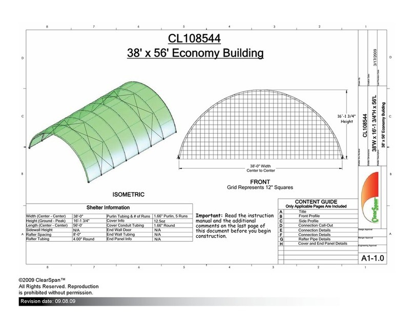
ClearSpan CL108544 User manual

ClearSpan
ClearSpan PB00590R3 User manual

ClearSpan
ClearSpan R030B00000F User manual

ClearSpan
ClearSpan 105595 User manual

ClearSpan
ClearSpan 2020SS User manual

ClearSpan
ClearSpan PB01110R4N User manual

ClearSpan
ClearSpan 4040SS User manual