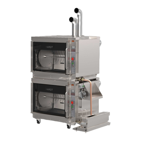
Hardt INFERNO 4500 User manual

Hardt Equipment Manufacturing Inc.
1400 50
th
Avenue, Lachine (Montreal)
Quebec, Canada, H8T 2V3
Technical Support
Tel: (800) 387-6847
(514) 631-7271
Fax: (514) 631-5443
Sales
Tel: (888) 848-4408
www.hardtequipment.com
INFERNO 4500
Gas
-
Fired, Self
-
Cleaning Rotisserie for CA
/MX/
S
HARDT
Responsive, Reliable Solutions
CUS-009-0028-11
This manual is to be left
with
th
e customer for future reference
.
Installation Manual

HARDT
Responsive, Reliable Solutions
Page 2 of 21 CUS-009-0028-11
FOR YOUR SAFETY
Do not store or use gasoline or other flammable vapors and
liquids in the vicinity of this or any other appliance. Keep
the area around the appliance free from all combustible
material.
WARNING
Improper installation, adjustment, alteration, service, or
maintenance can cause property damage, injury, or death.
Read the installation, operating and maintenance
instructions thoroughly before installing or servicing this
equipment.
IMPORTANT
You must post in a prominent location, instructions to be
followed in the event the user smells gas. Specific
instructions can be obtained from your local gas supplier.
NOTE
Hardt implements continuous improvements of its products
and reserves the right to change without notice.
Images shown in this manual are for reference only and may
appear different from actual models.
The terms Hardt®, Food Systems Resource®, Inferno®, Elemendt®, and the symbol depicting six circles, and
other distinctive terms, are registered and unregistered trademarks of Hardt Equipment Manufacturing, Inc. and
associated companies. Covered by U.S. Patent no. 6,127,659; U.S. Patent 7,060,942; U.S. Patent 7,241,977;
and U.S. Patent 10,051,995. Other patents pending.
© 2011 - 2019 Hardt Equipment Manufacturing, Inc. All rights reserved.

HARDT
Responsive, Reliable Solutions
CUS-009-0028-11 Page 3 of 21
1. Table of Contents
1.
Table of Contents ...............................................................................................................................3
2.
Before You Begin ................................................................................................................................4
About This Manual ............................................................................................................................................. 4
Who Should Install the Equipment ..................................................................................................................... 4
Equipment Safety............................................................................................................................................... 4
Tools & Equipment............................................................................................................................................. 5
Warranty Information.......................................................................................................................................... 5
3.
Equipment Diagrams ..........................................................................................................................6
Single Unit.......................................................................................................................................................... 6
Double Deck Unit ............................................................................................................................................... 7
4.
Receiving and npacking ...................................................................................................................8
Packing Checklist............................................................................................................................................... 8
Single Rotisserie ................................................................................................................................................ 9
4.2.1 Preparation.................................................................................................................................................9
4.2.2 Dismounting from Pallet.............................................................................................................................9
Double Deck Rotisserie.....................................................................................................................................11
4.3.1 Preparation...............................................................................................................................................11
4.3.2 Dismounting the Rotisseries from their Pallets.........................................................................................11
4.3.3 Stacking and Finishing Up........................................................................................................................12
5.
Installing the Equipment ................................................................................................................... 14
Venting..............................................................................................................................................................14
5.1.1 Hood Specification Recommendations.....................................................................................................14
5.1.2 Chimney Installation.................................................................................................................................15
5.1.3 Machine Room Ventilation Elbow Installation...........................................................................................15
Drains................................................................................................................................................................16
5.2.1 Plumbing the 1.5” [38.1 mm] grease drain line.........................................................................................16
5.2.1 Plumbing the 1”
NPT-M AutoClean drain line...........................................................................................16
Electrical............................................................................................................................................................17
Gas....................................................................................................................................................................18
5.4.1 Gas Pressure ...........................................................................................................................................18
5.4.2 Quick Disconnect Flexible Hose...............................................................................................................18
5.4.3 Making Gas Connections.........................................................................................................................19
Water.................................................................................................................................................................20
5.5.1 Water Softener.........................................................................................................................................20
5.5.2 Water Connection.....................................................................................................................................20
Degreaser..........................................................................................................................................................21
Accessories.......................................................................................................................................................21
5.7.1 Power Adapter (PA1, PA2, PA3)..............................................................................................................21
5.7.2 Grease Reservoir (GR-224, GR-124).......................................................................................................21

HARDT
Responsive, Reliable Solutions
Page 4 of 21 CUS-009-0028-11
2. Before You Begin
About This Manual
This manual contains information necessary for the installation of the HARDT Equipment Manufacturing
(hereafter referred to as Hardt) Inferno 4500 rotisserie. Retain this manual for future reference. To help the
reader in the utilization of this manual, certain information has been highlighted using the following
conventions:
INFORMATION THAT REFERS TO ACTIONS WHICH MAY HAVE CONSEQUENCES POTENTIALLY
DANGEROUS TO OPERATOR AND/OR THE EQUIPMENT.
Information for proper installation and functioning.
Additional important information.
Who Should Install the Equip ent
Only qualified persons should perform this installation. Gas, water and drain connections must be done by
persons qualified to do such tasks. All electrical connection installation must be done by a qualified
electrician. The strain relief cable must be installed by a qualified contractor.
Equip ent Safety
ENSURE THAT T
HE ELECTRICAL CORD I
S UNDAMAGED
AND NO BARE WIRES AR
E VISIBLE.
FOR YOUR SAFETY, DO NOT STORE OR USE GASOLINE OR OTHER FLAMMABLE VAPORS AND
LIQUIDS IN THE VICINITY OF THIS OR ANY OTHER APPLIANCE. KEEP THE AREA AROUND THE
APPLIANCE FREE FROM ALL COMBUSTIBLE MATERIALS.
IMPROPER INSTALLATION, ADJUSTMENT, ALTERATION, SERVICE, OR MAINTENANCE CAN CAUSE
PROPERTY DAMAGE, INJURY, OR DEATH. READ THIS INSTALLATION MANUAL THOROUGHLY
BEFORE INSTALLING THIS EQUIPMENT.
IF THE ROTISSERIE IS EQUIPPED WITH CASTERS, IT MUST BE SECURED TO THE BUILDING
STRUCTURE IN ORDER TO LIMIT THE MOVEMENT OF THE ROTISSERIE SO STRESS IS NOT
TRANSMITTED TO THE GAS CONNECTIONS.
IF YOU SMELL GAS, CLOSE THE GAS SUPPLY VALVE AND CALL YOUR LOCAL GAS TECHNICIAN
IMMEDIATELY.
AN ADEQUATE AIR SUPPLY MUST BE SUPPLIED TO THE ROTISSERIE AT ALL TIMES DURING
OPERATION TO ENSURE A PROPER FLOW OF COMBUSTION AND VENTILATION AIR.
FAILURE TO FOLLOW THE INSTRUCTIONS LISTED IN THIS DOCUMENT CAN RESULT IN INJURY,
DEATH, AND PROPERTY DAMAGE THAT MAY NOT BE COVERED BY YOUR WARRANTY.
•Read all documentation; only people who have read and understand this manual should install the
equipment.
•Do not operate this equipment if it is damaged in any way.
•Do not use unauthorized accessories.
Contact Hardt or an approved service provider immediately if any problems are encountered
with your equipment.

HARDT
Responsive, Reliable Solutions
CUS-009-0028-11 Page 5 of 21
Tools & Equip ent
The following tools are required to properly install the equipment:
•A forklift or similar lifting equipment is required for proper unloading and positioning of this
equipment
•Teflon tape
•Crowbar
•Claw hammer
•Tin snips
•Complete set of sockets with ratchet
•Set of wrenches and/or adjustable wrenches
•Screwdriver set
•Measuring tape
•Level
Warranty Infor ation
Warranty is conditional upon proper installation as described in this document. Please note that failure to
follow these instructions can result in damage to your equipment that is not covered under warranty.
Any damage or costs incurred due to any of the following situations will not be covered.
•Unauthorized repair by anyone other than a HARDT factory authorized service partner.
•Installation of non-Hardt replacement or service components.
•Alteration, misuse, or improper installation of the equipment.
•Failure to supply water, gas, or electrical supply within Hardt approved specifications.
•Use of unapproved cleaning materials and/or methods.
Please see your warranty document for additional details.

HARDT
Responsive, Reliable Solutions
Page 6 of 21 CUS-009-0028-11
3. Equip ent Diagra s
Single Unit
Figure 3-1
For a full list of available accessories, please visit
www.hardtequipment.com
or contact your sales account representative.
GREASE DRAIN
MANUAL DRAIN VALVE
HANDLE
CHIMNEY
CASTERS
(OPTION)
AUTOCLEAN DEGREASER INLET HOSE
HALOGEN LIGHT
ACCESS PANEL
OPTIONAL ACCESSORIES
POWER ADAPTER
HEATED GREASE RESERVOIR
POWER
CORD
CIRCUIT
BREAKER
GAS INLET
WATER INLET
RESTRAINING
CABLE
GAS
PRESSURE
GAUGE
MACHINE ROOM
VENTILATION
ELBOW

HARDT
Responsive, Reliable Solutions
CUS-009-0028-11 Page 7 of 21
Double Deck Unit
Figure 3-2
For a full list of available accessories, please visit
www.hardtequipment.com
or contact your sales account representative.
POWER
CORD
CIRCUIT
BREAKER
GAS INLET
WATER INLET
HALOGEN LIGHT
ACCESS PANEL
CHIMNEYS
HEATED
GREASE RESERVOIR
MANUAL
DRAIN VALVE
HANDLE
AUTOCLEAN DEGREASER INLET HOSE
GREASE DRAINS
POWER ADAPTER
TOP OVEN
OPTIONAL ACCESSORIES
BOTTOM OVEN
RESTRAINING
CABLE
CASTERS
MACHINE ROOM
VENTILATION
ELBOW
GAS
PRESSURE
GAUGE
CHIMNEY SUPPORT
BRACKET
AUTOCLEAN DEGREASER SHELF

HARDT
Responsive, Reliable Solutions
Page 8 of 21 CUS-009-0028-11
4. Receiving and Unpacking
If the unit is equipped with casters, inspect
for any damage that may have occurred during
shipping. If they are damaged, contact Hardt for replacements.
Care must be taken to ensure the rotisserie is not damaged or scratched in any way while
removing packaging or when removing the rotisserie from the pallet. Hardt recommends that
two people perform the unpacking.
WHEN LIFTING A ROTIS
SERIE WITH A WOODEN
RIG
, EN
SURE THE DOOR STAYS
OPEN AND
WON’T COME IN CONTACT WITH THE FORK LIFT. THE DOOR SHOULD ALWAYS STAY OPEN AT 90
DEGREES. ENSURE THE LIFTING RIG IS ALWAYS LEVEL, OTHERWISE THE BALANCE MIGHT BE
UPSET RISKING DAMAGE OR INJURY.
CONTACT OF THE FORK LIFT WITH ANY PART OF THE ROTISSERIE OTHER THAN THE LIFTING
RIG WILL RESULT IN DAMAGE TO THE ROTISSERIE.
Packing Checklist
Verify that all components have been shipped with your rotisserie(s) by
referring to the table below.
Equipment configuration
Included components
All configurations
Machine room ventilation elbow
(one per oven)
Wooden lifting rig
Flexible water hose (purchased separately)
1x for single rotisserie, 2x for double deck
Flexible gas hose & restrainer cable kit
(purchased separately)
1x for single rotisserie, 2x for double deck
Single rotisserie only Chimney stack
Double deck rotisseries
only
Chimneys:
A. Top rotisserie
B. Bottom rotisserie
Degreaser shelf
1.5" Grease drain tubing
(for top rotisserie)
B.
A.
PREINSTALLED BY HARDT

HARDT
Responsive, Reliable Solutions
CUS-009-0028-11 Page 9 of 21
Single Rotisserie
4.2.1 Preparation
1. Using tin snips or a similar cutting tool, cut the metal
packing straps. Care should be taken as the straps
are under tension and may snap when cut.
2. Remove all wrapping from the rotisserie. Be careful
not to scratch any surfaces if a knife is being used.
3. Remove all accessories and loose items from in and
around the equipment and place them aside.
4. Remove any wood blocks around the casters that
might hinder removal from the pallets.
Figure 4-1
4.2.2 Dis ounting fro Pallet
Figure 4-2
Note: To facilitate easier pallet dismounting, most
customers request an available wooden lifting rig to
be used with a forklift. The following instructions
describe how it is used.
1. Open the door fully on the rotisserie.
2. Insert the lifting rig inside the cooking cavity, taking
care not to damage the door. The proper orientation
is shown in Figure 4-1.
3. Align the rig so the shaft is between the two
stoppers built into the rig as shown in Figure 4-2.
4. Lift the rig and insert the two pins that hold the rig on
the shaft.
5. As shown in Figure 4-2, confirm that the lifting rig
supports the rotisserie from the rotating plates’ hubs
and NOT from the shaft.
6. The rotisserie may now be lifted by inserting the
forklift forks in the openings of the rig. Lift the
rotisserie off of its pallet as shown in Figure 4-3 and
set it firmly on the floor.
7. Carefully remove the lifting rig from the rotisserie.
8. Inspect the rotisserie for any remaining plastic left
over from the manufacturing + packing process and
remove if found. Be sure to remove the protective
foam blocks from the glass doors.
9. Position the rotisserie in the operation area.
10. Verify the rotisserie is level from front to back and
side to side. See Figure 4-4.
Figure 4-3
Figure 4-4
LIFT HERE
REMOVE WOOD
AROUND EACH LEG
PINS
HUB
SHAFT
STOPPERS

HARDT
Responsive, Reliable Solutions
Page 10 of 21 CUS-009-0028-11
11. Raise or lower the feet/optional casters to level the
unit if necessary. See Figure 4-5.
Figure 4-5
12. Inside the oven, verify that the flame shields are
secured in place (as they may have dislodged from
their locations during transport).
a. Ensure that the upper tab (A) and slot are
engaged.
b. Ensure that the 2 side slots (B) are
engaged to their corresponding wall tabs.
c. Ensure that the bottoms of both shields are
positioned behind the stopper (C).
Figure 4-6
LOCKING NUT
LOCK
UNLOCK
RAISE
UNIT
LOWER
UNIT
RAISE
UNIT
LOWER UNIT

HARDT
Responsive, Reliable Solutions
CUS-009-0028-11 Page 11 of 21
Double Deck Rotisserie
4.3.1 Preparation
1. Using tin snips or a similar cutting tool, cut the metal packing straps. Care should be taken as the
straps are under tension and may snap when cut.
2. Remove all wrapping from the rotisserie. Be careful not to scratch any surfaces if a knife is being
used.
3. Remove all accessories and loose items from in and around the equipment and place them aside.
4. Remove all wood blocks around the casters that might hinder the removal from the pallets.
5. The bottom rotisserie (the one with casters) must be unpacked and set on the floor first as described
Section 4.3.2.
4.3.2 Dis ounting the Rotisseries fro their Pallets
A wooden lifting rig is packaged with the bottom
rotisserie. It is used with a forklift for both pallet
dismounting and in the stacking procedure. The
following instructions describe how it is used.
Figure 4-7
1. Open the door on the bottom rotisserie.
2. Insert the lifting rig inside the cooking cavity, taking
care not to damage the door. The proper orientation
is shown in Figure 4-7.
3. Align the rig so that the shaft is between the two
stoppers built into the jig as shown in Figure 4-8.
4. Lift the jig and insert the tow pins that hold the jig on
the shaft.
5. As shown in Figure 4-8, confirm that the lifting rig
supports the rotisserie from the rotating plates’ hubs
and NOT from the shaft.
6. The rotisserie may now be lifted by inserting the lift’s
forks in the openings of the rig. Lift the bottom
rotisserie off of its pallet and set it on the floor as
shown in Figure 4-9.
7. Carefully remove the wooden lifting rig from the
bottom rotisserie and install it into the top rotisserie
(the rotisserie without the casters) using the same
instructions.
8. Proceed to Section 4.3.3.
Figure 4-8
Figure 4-9
LIFT HERE
REMOVE WOOD BLOCKS S
ECURING ROTISSERIE
PINS
HUB
SHAFT
STOPPERS

HARDT
Responsive, Reliable Solutions
Page 12 of 21 CUS-009-0028-11
4.3.3 Stacking and Finishing Up
1. Ensure the screws holding the mounting bracket on
the roof of the bottom rotisserie are tight as shown
in Figure 4-10.
2. Lift the top rotisserie by inserting the lift’s forks in the
openings of the previously installed rig.
3. Place the top rotisserie on to the bottom one. The
four tabs on the spacer must be inserted inside the
frame of the top rotisserie. The holes in the base of
the top rotisserie must align with the holes in the
tabs on the spacer of the bottom rotisserie. See
Figure 4-11 and Figure 4-12.
4. Install bolts and washers as shown in Figure 4-12.
5. Remove the wood lifting rig from the top rotisserie.
Be careful not to damage the doors or other
components of the rotisseries.
6. Inspect rotisseries for any remaining plastic left over
from the manufacturing and packing process,
remove if found. Be sure to remove the protective
foam blocks from the glass doors.
7. Place the double decked rotisserie in its operational
area.
8. Verify that the double deck installation is levelled
from front to back and side to side.
See Figure 4-13.
Figure 4-10
Figure 4-11
Figure 4-12
Figure 4-13
ENSURE BOLTS ARE
TIGHT (8X)
MOUNTING BRACKET
MOUNTING
BRACKET
TAB
4X

HARDT
Responsive, Reliable Solutions
CUS-009-0028-11 Page 13 of 21
9. Raise or lower the casters if necessary.
See Figure 4-14.
Figure 4-14
W
hen adjusting, it is necessary to slightly
lift
the
corner of the double deck rotisserie at each
caster location in order to prevent thread
damage.
Hardt recommends the use of a pallet jack or
lever for this procedure.
10. Inside each oven, verify that the flame shields are
secured in place (as they may have dislodged from
their locations during transport).
a. Ensure that the upper tab (A) and slot are
engaged.
b. Ensure that the 2 side slots (B) are
engaged to their corresponding wall tabs.
c. Ensure that the bottoms of both shields are
positioned behind the stopper (C).
Figure 4-15
RAISE
UNIT
LOWER
UNIT
UNLOCK
LOCK
LOCKING NUT

HARDT
Responsive, Reliable Solutions
Page 14 of 21 CUS-009-0028-11
5. Installing the Equip ent
Venting
The Inferno 4500 rotisserie is designed to be used with a hood or canopy.
The Inferno
4500
rotisserie must vent with HARDT
-
supplied flues.
Install the hood and make-up so that air is NOT being blown into nor pulled out of the rotisserie. The
hood should remove exhaust gases without disturbing the air within the rotisserie.
An adequate air supply must be supplied to the unit at all times during operation to ensure proper flow
of combustion and ventilation air.
Please consult Hardt if further guidance is needed.
5.1.1 Hood Specification Reco endations
Hood Type
Hardt recommends a Type 1 / Class A grease hood with filters and a fire suppression system in accordance
with local and state regulations.
Hood Make-up Air / Exhaust
For canopy make-up air and exhaust flow rates, please refer to local and state codes and hood manufacturer
specifications.
Minimum Hood Overhang:
•From rear and sides of rotisserie: 6.0" [152 mm]
•From front of rotisserie: 12.0" [305 mm]
These values may vary, depending on local and state
codes.
Hood internal components must not interfere with the
rotisserie’s chimney, as no modification to the rotisserie’s
chimney configuration may be made.
The lower edge of the hood must be at a height that
allows the oven (without chimney stack) to be rolled
underneath.
Ensure that the fire suppression nozzles do not prevent
the rotisserie from being moved for cleaning.
Figure 5-1
FAILURE TO PROVIDE T
HE MINIMUM CLEARANCE
S TO COMBUSTIBLES AS
SPECIFIED ON THE
NAMEPLATE IS PROHIBITED BY LAW AND CAN CAUSE PROPERTY DAMAGE, INJURY AND CAN VOID
YOUR WARRANTY.
DO NOT LOCATE THE ROTISSERIE IN AN AREA WHERE THE CONTROL SIDE IS NEXT TO FRYERS,
BROILERS OR OTHER APPLIANCES THAT EMIT GREASE, SMOKE, HUMIDITY, FLOUR, ETC.

HARDT
Responsive, Reliable Solutions
CUS-009-0028-11 Page 15 of 21
5.1.2 Chi ney Installation
The screws required for mounting the chimneys should
already be located in the vents to which the chimneys will be
connected.
Double De k Rotisseries
•Install the upper and lower chimneys onto the rotisserie
as shown in Figure 5-2.
•Ensure that both chimneys are oriented towards the
front and are parallel to each other.
•Ensure both chimneys are held in place by the support
bracket.
Single Rotisseries
•Install only the upper chimney as shown in Figure 5-2.
No support bracket is required.
•Ensure that the chimney is oriented towards the front.
5.1.3 Machine Roo Ventilation Elbow Installation
•Install the machine room ventilation elbow(s), ensuring
an orientation of 45° towards the fan box the as shown
in Figure 5-2.
Figure 5-2
CHIMNEY(S)
LOWER
SUPPORT BRACKET
(DOUBLE DECK ONLY)
MACHINE ROOM
VENTILATION ELBOW(S)
UPPER

HARDT
Responsive, Reliable Solutions
Page 16 of 21 CUS-009-0028-11
Drains
The Inferno 4500 is equipped with two drains (per rotisserie). One drain is for the drainage of the cooking
effluent (1.5" [38.1 mm] diameter) and the other is for the AutoClean drain line (1” NPT-M).
Any liquid drained from the rotisserie will be very hot, it is recommended that copper tubing or other
high temperature rated piping be used for the drain connections.
5.2.1 Plu bing the 1.5” [38.1 ] grease drain line
The 1.5" [38.1 mm] drain line is the drain line coming from the
drip pan. The effluent from this drain contains high
concentrations of FOG’s (Fats, Oils and Grease) produced
during the cooking process and must be collected in
containers or a grease collection reservoir (Such as Hardt’s
optional GR Series heated grease collection reservoirs) and
transferred to a rendering barrel for proper disposal.
The top rotisserie on a double deck and the single rotisserie
will require the grease drain tubing to be screwed into place as
shown in Figure 5-3. Note: Single units are usually shipped
with the drain tubing preinstalled.
Figure 5-3
5.2.1 Plu bing the 1”
NPT-M AutoClean drain line
Make sure that the AutoClean drain is plumbed in a manner which allows the rotisserie to remain
mobile for servicing. The effluent from this drain may contain Fats, Oils and Greases (FOGs).
Local ordinances may require a backflow prevention device. Consult the authority having jurisdiction
to determine what regulations are in force for appliances of this type as well as regulations regarding
the disposal of grease laden water and FOGs.
The 1” NPT-M AutoClean drain lines from double deck rotisseries must NEVER be plumbed together.
Doing so will cause improper drainage performance and will lead to other plumbing problems.
The 1” NPT-M drain line is located at the exterior lower rear
right corner of the rotisserie. This drain is for the AutoClean
process and is used to drain the water/detergents used during
this process. It may be plumbed directly, as per the
customers’ requirements, to the waste water drainage system.
The part to be used to make the connection is a copper tube
fitting female adapter (1” NPT) for soldering joint piping (Not
sold by Hardt but available through local standard
plumber outlets).
Figure 5-4
SCREW UPPER
TUBING INTO
PLACE
1.5” [38.1 MM]
GREASE DRAIN(S)
1” NPT-M
AUTOCLEAN
DRAIN(S)
COPPER TUBE
FITTING FEMALE
ADAPTER 1"
NPT
COPPER
SOLDERED
JOINTS 1" TUBES &
90° COPPER ELBOW

HARDT
Responsive, Reliable Solutions
CUS-009-0028-11 Page 17 of 21
Electrical
THE ROTISSER
IE IS SUPPLIED WITH
A 6.0 FOOT [183
0 M
M]
LONG ELECTRICAL CORD
. THE CORD IS
EQUIPPED WITH A THREE-PRONG (GROUNDING) PLUG FOR YOUR PROTECTION AGAINST SHOCK
HAZARD AND SHOULD BE PLUGGED DIRECTLY INTO A PROPERLY GROUNDED THREE-PRONG
RECEPTACLE. DO NOT CUT OR REMOVE THE GROUNDING PRONG FROM THIS PLUG.
THE APPLIANCE MUST BE ELECTRICALLY GROUNDED IN ACCORDANCE WITH LOCAL CODES OR, IN
THE ABSENCE OF LOCAL CODES, WITH THE NATIONAL ELECTRICAL CODE, ANSI/NFPA 70, OR THE
CANADIAN ELECTRICAL CODE, CSA C22.2, AS APPLICABLE.
IF REQUIRED BY LOCAL REGULATION, A GROUND FAULT CURRENT INTERRUPTER (GFCI) MUST BE
INSTALLED BY A QUALIFIED ELECTRICIAN.
The appliance electrical diagram is located on the inside surface of the right side access panel.
WHEN THE OVEN IS PLU
GGED IN, THERE ARE P
OTENTIALLY DANGEROUS
VOLTAGES PRESENT IN
THE
CONTROL CIRCUITS.
DO NOT OPEN THE ELECTRICAL COMPARTMENT AS POTENTIALLY LETHAL VOLTAGES ARE PRESENT
INSIDE.

HARDT
Responsive, Reliable Solutions
Page 18 of 21 CUS-009-0028-11
Gas
The installation of the gas supply must be done by a qualified plumber in accordance with local gas codes; or in the
absence of local codes in accordance with the National Fuel Gas Code; ANSI Z223.1/NFPA 54, or the Natural Gas
and Propane Installation Code; CSA B149.1, as applicable including:
•During a pressure test of the gas supply piping system, the appliance must be completely isolated by
disconnecting the quick disconnect gas line if the test pressure is above 0.5 psi [3.5 kPa]. If the test
pressure is equal to or below 0.5 psi [3.5 kPa], only the appliances manual shutoff valve must be closed.
THE ROTISSERIE IS
VERY HOT WHEN OPERAT
ING. MAKE SURE THAT
THE MAIN GAS VALVE I
S
INSTALLED IN A LOCATION EASILY ACCESSIBLE TO THE EMPLOYEES.
ENSURE THE FACILITY GAS SUPPLY IS TURNED OFF BEFORE OPENING ANY CONNECTIONS PRIOR TO
OR DURING THE GAS HOSE INSTALLATION AND CONNECTION OF THE ROTISSERIE.
A RESTRAINING DEVICE MUST BE INSTALLED SUCH THAT THE ROTISSERIE MOVEMENT IS LIMITED
WITHOUT RELYING ON THE 'QUICK-DISCONNECT' HARDWARE OR ITS ASSOCIATED PIPING.
It is required that Inferno 4500 rotisseries be equipped with quick-disconnect gas/water installation
hardware.
FOR A ROTISSERIE EQU
IPPED WITH CASTERS,
IT IS ALSO REQUIRED
THAT IT BE EQUIPPED
WITH A
CONNECTOR THAT COMPLIES WITH THE STANDARD FOR CONNECTORS FOR MOVABLE GAS
APPLIANCES, ANSI Z21.69 OR CONNECTORS FOR MOVABLE GAS APPLIANCES, CAN/CSA-6.16, AND A
QUICK DISCONNECT DEVICE THAT COMPLIES WITH THE STANDARD FOR QUICK DISCONNECT DEVICES
FOR USE WITH GAS FUEL, ANSI Z21.41 (CSA 6.9).
5.4.1 Gas Pressure
Natural Gas Incoming Pressure:
7 inches W.C. [1.74 kPa] – 12 inches W.C. [2.99 kPa].
Propane Incoming Pressure: 11 inches W.C. [2.74 kPa] – 12 inches W.C. [2.99 kPa].
5.4.2 Quick Disconnect Flexible Hose
All hardware required for a quick-disconnect gas/water installation may be purchased from HARDT. The quick-
disconnect flexible hose and pipe adapter (both shown in Figure 5-5) are available from Hardt.
Figure 5-5
QUICK-DISCONNECT FITTING,
PIPE ADAPTER
QUICK-DISCONNECT
HOSE FITTING
FLEXIBLE GAS HOSE
CONNECT THIS END TO
SUPPLY

HARDT
Responsive, Reliable Solutions
CUS-009-0028-11 Page 19 of 21
5.4.3 Making Gas Connections
1. Connect the restraining cable to the anchor hole located
at the rear of the rotisserie (see Figure 5-6) and to the
wall using the wall-mount bracket. The restraining cable
and the wall mount bracket are supplied with the quick-
disconnect kit (the kit must be ordered along with the
rotisserie). The wall mount bracket must be installed by
a qualified contractor.
2. The gas connection is located behind the right rear
corner of the rotisserie. See Figure 5-6.
3. Apply an approved thread sealant to the threaded pipe
end on the gas pipe extending from the rear of the
rotisserie.
4. Screw the Quick-Disconnect fitting (pipe adapter shown
in Figure 5-5) onto the threaded connection.
5. Attach the flexible gas supply hose to the facility gas
supply line and connect the gas to the rotisserie by
sliding the Quick-Disconnect hose fitting onto the pipe
adapter.
6. Open the main gas valve from the facility gas supply
line(s).
7. Check all hoses, fittings and connections for leaks prior
to operating the rotisserie.
Figure 5-6
FAILURE TO CHECK FOR LEAKS MAY RESULT IN INJURY OR DEATH.
GAS CONNECTION,
THREADED PIPE
END
RESTRAINING CABLE
ANCHOR LOCATION

HARDT
Responsive, Reliable Solutions
Page 20 of 21 CUS-009-0028-11
Water
The manufacturers' recommended installation instructions DO NOT supersede any local plumbing
regulations. Installation must be done by a certified tradesman and in accordance with all code
requirements.
Each rotisserie requires a connection to a HOT water source. It is recommended that high
temperature rated hoses and pipes are used to provide water to each rotisserie.
Each rotisserie requires a water pressure of 30 – 60 psi [210 - 410 kPa] at inlet.
5.5.1 Water Softener
In locations where the water hardness exceed 4.0 GPG (70.0 PPM) a water softener is required. External
softeners are not required in locations that have integrated water softening systems in their potable water supply
lines. For all other locations it is recommended that you install an external water softener system. The softener
should be installed on the water supply line to the rotisserie and be connected to the water inlet located at the
back of the rotisserie. DO NOT MOUNT THE WATER SOFTENER DIRECTLY ON THE ROTISSERIE.
5.5.2 Water Connection
1. Ensure that the facility water supply is
turned off.
2. Locate the water inlet connection at
the lower rear right corner of the
rotisserie (see Figure 5-7).
3. Connect the rotisserie to the water
supply line by using a flexible hose. If
using the connection kit available from
Hardt, assemble as shown in
Figure 5-7.
WRAP 3 (MAXIMUM) CLOCKWISE
TURNS OF TEFLON TAPE TO ALL
EXTERNAL THREADS.
Notes:
(1) If the rotisserie does not have
casters, it can be connected by using
direct hard plumbing.
(2) Some rotisseries are built with
bottom connections (that differ from
the plumbing location shown in
Figure 5-7) but the setup and
instructions are the same.
4. Ensure that the drain valve handle in
front of the unit is set to ‘CLEAN’.
Open the water supply valve and
check for leaks.
Figure 5-7
ALL SUPPLY SIDE WATER FITTINGS MUST BE INSTALLED BY A QUALIFIED PLUMBER.
WATER INLET
CONNECTION
1/2" NPT-M
QUICK-DISCONNECT FITTING
QUICK-DISCONNECT COUPLING
MALE TO MALE
COUPLINGS (2X)
WRAP 3 (MAXIMUM)
CLOCKWISE TURNS
OF TEFLON TAPE
TO ALL EXTERNAL
THREADS
OPTIONAL WATER QUICK-
DISCONNECT KIT AVAILABLE:
6-FT WATER HOSE
Other manuals for INFERNO 4500
1
Table of contents
Other Hardt Commercial Food Equipment manuals
Hardt
Hardt INFERNO 3500 Manual

Hardt
Hardt INFERNO 3500 User manual

Hardt
Hardt INFERNO 3500 Installation manual

Hardt
Hardt Elemendt 1000 Use and care manual
Hardt
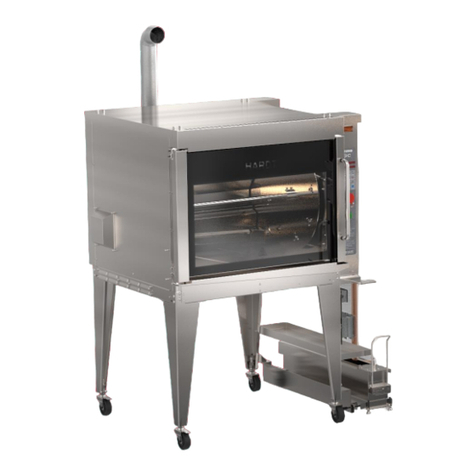
Hardt Inferno GC User manual

Hardt
Hardt Inferno GC User manual
Hardt
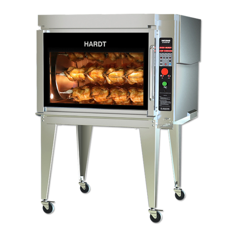
Hardt Inferno 3500 - C Installation manual

Hardt
Hardt Elemendt 1000 User manual

Hardt
Hardt Elemendt 1000 User manual

Hardt
Hardt Blaze - C User manual
