HARTING Han 1A User manual
09 10 008 3100 / 99.00
5.
Schieben Sie das Schirmelement unter das Schirmgeflecht (Abb. 2 &3).
5. Push the shielding element under the shielding braid (Fig. 2 & 3).
5. Poussez l’élément de blindage sous la tresse de blindage (fig. 2 & 3).
6. Legen Sie das Schirmgeflecht gleichmäßig auf das Schirmelement
auf (Abb. 3, ⑥).
6. Spread the shielding braid evenly over the shielding element
(figure 3, ⑥).
6.
Posez la tresse de blindage à plat sur l’élément de blindage (fig. 3, ⑥).
7.
Setzen Sie die Kontakte in die seitlichen Kavitäten des Kontaktträger-
sein (Abb. 3, ⑦). Verwenden Sie zur Kodierung die farbigen Kennzeich-
nungen auf dem Kontaktträger.
7. Insert the contacts into the lateral cavities of the contact
holder (Fig. 3, ⑦). For assignment use the color identification
marks on the contact holder.
7 Insérez les contacts dans les cavités latérales du support de contact
(fig. 3, ⑦). Pour appliquer une codage, utilisez les marques d’identifica-
tion de couleur sur le support de contacts.
Abbildung · Figure · Figure 4 : Kodierung Kontaktträgerund Isolierkörper /
Coding contact holder and insulation body / Codage du sup-
port de contact et isolant
8.
Schieben Sie den Isolierkörper auf den Kontakthalter, bis er einrastet
(Abb. 4).
8. Push the insulation body on the contact holder, until it clicks
into place (Fig. 4).
8. Glissez l’isolant sur le support de contact, jusqu’à ce qu’il s’enclenche
en place (fig. 4).
HARTING Electric GmbH & Co. KG |
Wilhelm-Harting-Straße 1 | D-32339 Espelkamp
Fon: +49 57 72 47-97100 | Fax: +49 57 72 47-124
Internet: www.HARTING.com |
E-Mail: [email protected]
Deutsch
English
Français
Han®1 A X-coded, female
Artikelnummern · Part numbers · Références
09 10 008 3100 / 09 10 008 3105
www.HARTING.com
Montageanleitung · Assembly instructions ·
Schéma d’assemblage
1. Schieben Sie den Kabeladapter schrittweise auf das Kabel. Ein Kabel-
durchmesser zwischen 5,7 und 10 mm ist erforderlich.
1. Slide the cable adapter stepwise onto the cable. A cable diameter
between 5.7 and 10 mm is required.
1. Glissez l’adaptateur de câble sur le câble en plusieurs étapes. Utilisez
un câble d’un diamètre compris entre 5,7 et 10 mm.
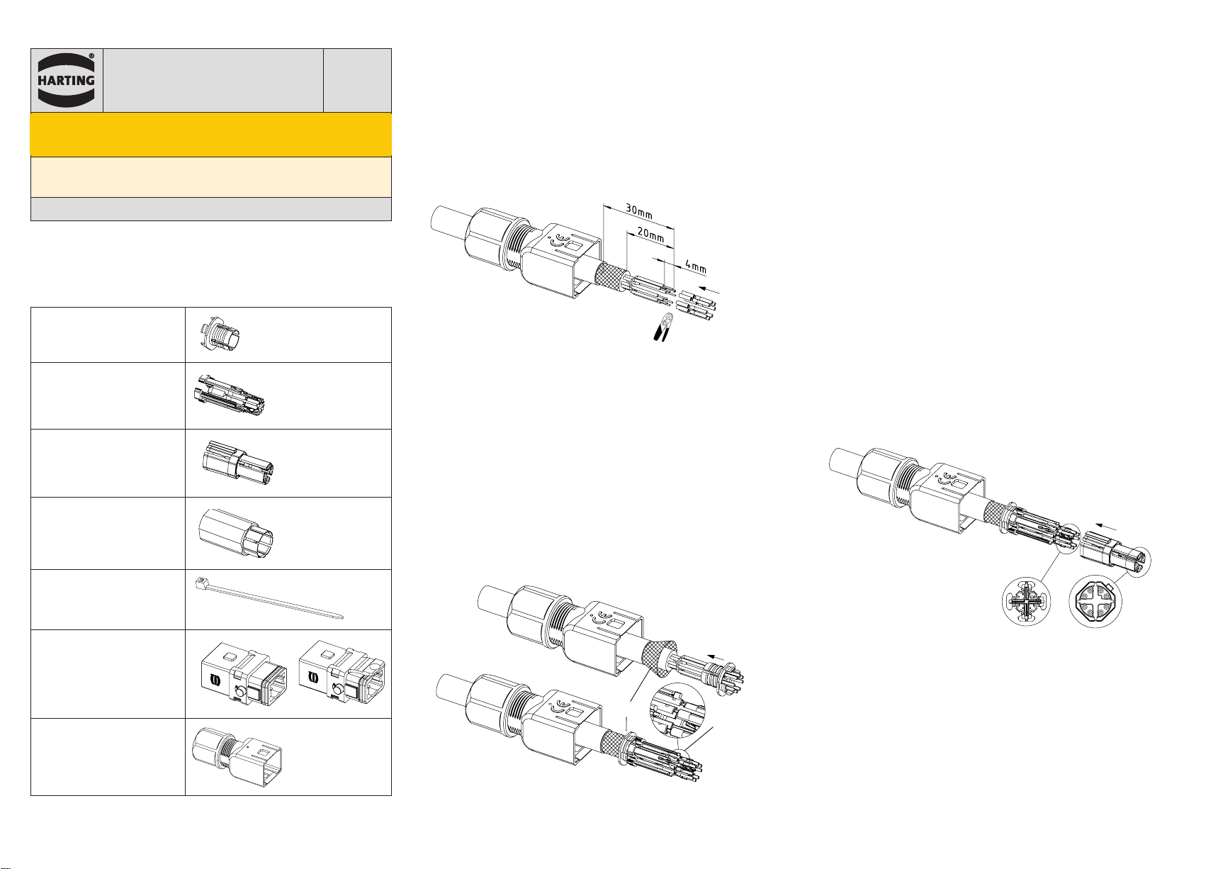
Abbildung · Figure · Figure 1 :
Abisolierlängen /Stripping lengths/ Longueurs à dénuder
2. Isolieren Sie den Kabelmantel ab wie in der Abb. 1 beschrieben.
2. Remove the cable sheath as indicated by Figure 1.
2. Denudez la gaine du câble comme indiqué dans le dessin, fig. 1.
3. Kürzen Sie die Paarschirmung.
3. Shorten the pair shielding.
3. Raccourcirez le blindage par paires.
4.
Entfernen Sie die Aderisolierung und crimpen Sie die Kontakte (Abb. 1).
4. Remove the wire insulation and terminate the crimp contacts
(Fig. 1).
4. Dégagez l’isolant des fils et sertissez les contacts (fig. 1).
⑦
⑥
Abbildung · Figures · Figures 2 & 3 : Schirmgeflecht anlegen / Spreading
the shielding braid/ Mettre en place la tresse de blindage
Inhalt · Content · Contenu
Schirmelement
Shielding element
Élément de blindage
Kontaktträger
Contact holder
Support de contact
Isolierkörper
Insulation body
Corps isolant
Schirmhülse
Shielding sleeve
Manchon de blindage
Kabelbinder
Cable tie
Attache de câble
Gehäuse
Hood/housing
Capot / embase
Kabeladapter*
Cable adapter*
Adaptateur de câble*
* Nicht Teil der Lieferung /Not within scope of delivery/N’est pas compris dans la livraison

Werkzeug-Einstellungen · Tool settings · Réglages des outils
Werkzeug / Tool /
Outil
Locator / Locator /
Positionneur
Kontakte /
Contacts/Contacts
09 99 000 0501 09 99 000 0525 21 01 100 9021
21 01 100 9023
Kontakt /
Contact/
Contact
Artikelnum-
mer / Part
number/
Référence
AWG
Werkzeugeinstellung/
Tool settings /
Réglage de l’outil
Har-speed,
Buchse/
female /
femelle
21 01 100 9021
23 5
24 5
26 4
Har-speed
M12, Buch-
se
/fema-
le / femelle
21 01 100 9023
24 5
26 4
28 3
Abbildung · Figure · Figure 5 : Schirmhülse aufschieben/
Pushing the shielding sleeve / Glisser le manchon de blindage
9. Schieben Sie die Schirmhülse über den Isolierkörper bis an den An-
schlag des Schirmelements (Abb. 5).
9. Slide the shielding sleeve over the insulation body, all the way
up to the shielding element (Fig. 5).
9. Glissez le manchon de blindage sur le corps isolant jusqu’à la butée de
l’élément de blindage (fig. 5).
Abbildung ·Figure ·Figure 6 : Kupferfolie über Schirmung /
Copper foil on shielding braid /
Feuille de cuivre sur la tresse de blindage
Abbildung · Figure · Figure 9 : Kodierung / Coding/ Codage
12. Schieben Sie den Kabeladapter auf das Gehäuse, bis er einrastet. Be-
festigen Sie die Kabelverschraubung mit einem Schraubenschlüssel SW
18 und verwenden Sie dabei ein Anzugsdrehmoment von 1,5 bis 1,8 Nm
(Abb. 9).
12. Slide the cable adapter onto the hood/housing until it clicks into
place. Fasten the cable gland with a spanner A/F 18, applying a
tightening torque of 1.5 to 1.8 Nm (Fig. 9).
12. Faites glisser l’adaptateur de câble sur le boîtier jusqu’à ce qu’il s’en-
clenche en place. Fixez le presse-étoupe avec une ouverture de clé de
18 mm et un couple de serrage de 1,5 à 1,8 Nm (fig. 9).
Montageanleitung, Art.-Nr. 09 10 008 3100 / 99.00 2020-03-31
Irrtum und technische Änderungen vorbehalten.
Assembly instructions, part no. 09 10 008 3100 / 99.00 2020-03 -31
Errors and technical changes excepted.
Schéma d’assemblage, référence 09 10 008 3100 / 99.00 2020-03-31
Sauf erreur et changements techniques.
10. Für eine optimale Schirmübertragung empfehlen wir die Verwendung
eines Kupferbandes (Abb. 6).
10. For optimum shielding transmission, we recommend the use of a
copper tape (Fig. 6).
10.
Nous recommandons l’utilisation d’une feuille de cuivre pour une trans-
mission optimale du blindage (fig. 6).
Abbildung · Figure · Figure 7 : Schirmgeflecht fixieren /
Fixing the shielding braid / Fixer la tresse de blindage
10. Fixieren Sie das Schirmgeflecht mithilfe eines Kabelbinders (Abb. 7).
10. Fix the shielding braid by using a cable tie (Fig. 7).
10. Fixez la tresse de blindage à l’aide d’un attache de câble (fig. 7).
Abbildung · Figure · Figure 8 : Montage Baugruppe /
assembly of components/ Assembler les composants
11. Schieben Sie die Baugruppe in das Gehäuse (Abb. 8), achten Sie da-
bei auf die Kodierung.
11. Push the preassembled unit into the housing, thereby observing
the coding (Fig. 8).
11. Insérez le module pre-assemblé dans le boîtier, en observant le co-
dage (fig. 8).
This manual suits for next models
3
Other HARTING Cables And Connectors manuals

HARTING
HARTING M12-PP-CC-CRIMP-5P-ACOD-M-ANG-SHLD User manual

HARTING
HARTING Han 1 A X-coded User manual

HARTING
HARTING Han 09 10 004 3100 User manual

HARTING
HARTING Han 10 B User manual

HARTING
HARTING M12 User manual

HARTING
HARTING Han 09 10 004 3001 User manual

HARTING
HARTING Han ES Press User manual

HARTING
HARTING Han M23 User manual

HARTING
HARTING Han F+B 4/4 + PE User manual

HARTING
HARTING Han-Yellock 30 User manual


