manuals.online logo
Brands
  1. Home
  2. •
  3. Brands
  4. •
  5. HARTING
  6. •
  7. Cables And Connectors
  8. •
  9. HARTING M12-PP-CC-CRIMP-5P-ACOD-M-ANG-SHLD User manual

HARTING M12-PP-CC-CRIMP-5P-ACOD-M-ANG-SHLD User manual

HARTING Electronics GmbH
P.O. Box 14 73 | D-32339 Espelkamp
[email protected]
Deutsch
ENGLISH
Français
Rundsteckverbinder · Circular Connector · Connecteur circulaire
M12 PushPull, 4/5 poles, A-coded, male, angled
Bestell-Nummer · Part number · Réf. article
21 03 821 3530
www.HARTING.com
Inhalt · Content · Contenu
Dichtungskamm
Seal holder
Peigne de joints
Überwurfmutter
Lock nut
L’é cro u
Winkelstück
Angular piece
Pièce angulaire
Kontaktträger
Contact holder
Support de contact
Montagehilfe
Assembly aid
Dispositif de montage
Isolierkörper
Insulation body
Corps isolant
Steckverbindergehäuse
Metal housing
Boîtier
Montageanleitung · Assembly instruction
Instructions d’assemblage
1. Wählen Sie die passende Dichtung aus dem Dichtungskamm aus
(Abb. 1). Bitte berücksichtigen Sie unsere Angaben gemäß folgender
Tabelle.
1. Select the proper seal (Fig. 1). Please consider the information in
following table.
1. Choisir le joint approprié (Fig. 1). S’il vous plaît envisager nos données
selon le tableau suivant.
5.7 - 6.9 mm
6.5 - 7.7 mm
7.5 - 8.8 mm
Abbildung
figure · figure 1
Hersteller
Manufacturer
Fabricant
Beschreibung
Description
Description
Benötigte Dichtung
Required seal
Joint nécessaire
Helukabel TRONIC-CY (LIY-CY)
5 x 0,50 QMM / 16005 500V
01560080314 CE RoHS 12/15 small seal (A)
Nexans
DTREN150002 - 300V -
4x0,5mm² CS - Qadrax
100 Ohms - 239 - Filotex P EDE
2PK211
big seal (C)
2. Schieben Sie die Überwurfmutter und die ausgewählte Dichtung auf
das Kabel (Abb. 2).
2. Push the lock nut and selected seal over the cable (Fig. 2).
2. Glisser l’écrou et le joint choisi sur le câble (Fig. 2).
3. Entfernen Sie den Kabelmantel (Abb. 2).
3. Remove cable jacket (Fig. 2).
3. Dénuder de la gaine du câble (Fig. 2).
4. Ziehen Sie das Schirmgeflecht zurück. Wenn nötig entfernen Sie die
Folien (Abb. 2).
4. Pull back the shielding braid. Remove foils if necessary (Fig. 2).
4. Rabattre la tresse de blindage. Enlever éventuellement le film de pro-
tection si nécessaire (Fig. 2).
5. Entfernen Sie die Aderisolierung und crimpen Sie die Kontakte an
(Abb. 2).
5. Remove wire insulation and terminate the crimp contacts (Fig. 2).
5. Dénuder les isolants des fils et sertir les contacts (Fig. 2).
010203040mm M 1:1
43941
Abbildung · figure · figure 2
Werkzeug / Tool / Outil: 09 99 000 0501
Locator / Locator / Locator: 09 99 000 0531
Kontakte / Contacts / Contacts: 09 67 000 3576 AWG 22-18
09 67 000 8576 AWG 24-20
09 67 000 5576 AWG 26-22
Bestell-Nummer
Part Number
Réf. article
AWG Werkzeugeinstellung
Tool settings
Réglage de l‘outil
09 67 000 3576
18 6
20 6
22 5
09 67 000 8576 20, 22, 24 6
09 67 000 5576 22, 24, 26 6
6. Ordnen Sie die Adern entsprechend der Pinbelegung sowie Kabelab-
gangsrichtung an. Die Abgangsrichtung kann in 90° Schritten verän-
dert werden (Abb. 3). Schieben Sie das Winkelstück auf das Kabel
unter Beachtung der Kabelabgangsrichtung (Abb. 3). Bei einem 4-po-
ligen Anschluss fahren Sie mit Schritt 9 fort. Bei einem 5-poligen An-
schluss fahren Sie mit Schritt 7 fort.
6. Arrange the wires according to the pin assignment as well
as cable outlet direction. The cable outlet direction can be
changed in 90° steps (Fig. 3). Slide the angular piece over the
cable, considering the cable outlet direction (Fig. 3). For a 4
pole connector continue from step 9. For a 5 pole connector
continue from step 7.
6. Disposer les fils selon le positionnement des broches ainsi que la di-
rection de sortie de câble. La direction de sortie du câble peut être
modifiée par incréments de 90° (Fig. 3). Glisser la pièce angulaire sur
le câble et tenir compte la direction de sortie de câble (Fig. 3). Pour
une connexion 4 pôles, passer à l’étape 9. Pour une connexion 5 pôles,
passer à l’étape 7.
Abbildung · figure · figure 3
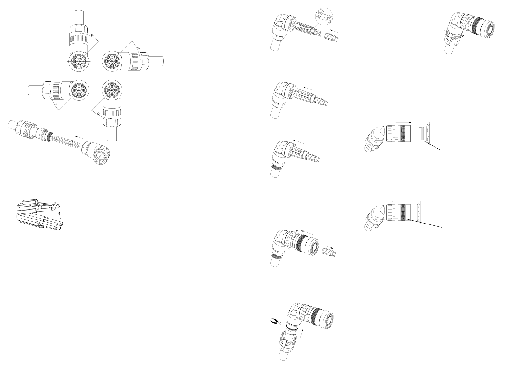
7. Klappen Sie den Kontaktträger auseinander (Abb. 4).
7. Open the contact holder (Fig. 4).
7. Ouvrir le support de contact (Fig. 4).
 Abbildung · figure · figure 4
8. Legen Sie den Kontakt in die mittlere Kontaktkammer des Kontakt-
trägers ein und setzen Sie den Kontaktträger zusammen (Abb. 5).
8. Insert the contact into middle cavity of the contact holder and
put the contact holder together (Fig. 5).
8. Insérer le contact dans la cavité centrale du support de contact et as-
sembler le support de contact (Fig. 5).
9. Legen Sie die Kontakte seitlich in den Kontaktträger ein (Abb. 5). Für
die Pinbelegung orientieren Sie sich bei Verwendung einer 4-adrigen
Leitung an der farblichen Kennzeichnung auf dem Kontaktträger und
bei Verwendung einer 5-adrigen Leitung an der Nummerierung auf
dem Kontaktträger. Setzen Sie die Montagehilfe auf (Abb. 5).
9. Insert the contacts into side cavities of the contact holder (Fig.
5). For the pin assignment use the color identification marks
on the contact holder in case of using a 4 wire cable and the
numbering on the contact holder in case of using a 5 wire cable.
Put the assembly aid on the contacts (Fig. 5).
9. Insérer latéralement les contacts dans les cavités (Fig. 5). Pour le
positionnement des broches, s’orienter à la couleur sur le support de
contact en cas d’utilisation d’un fil à 4 brins et à la numérotation sur le
support de contact en cas d’utilisation d’un fil à 5 brins. Poser le dispo-
sitif de montage (Fig. 5).
Abbildung · figure · figure 5
10. Schieben Sie den Isolierkörper auf den Kontaktträger, bis dieser ein-
rastet. (Abb. 6).
10. Slide the insulation body on
the contact holder until it
clicks into place (Fig. 6).
10. Glisser le corps isolant sur le
support de contact jusqu’à ce
qu’il clique (Fig. 6).
Abbildung · figure · figure 6
11. Drücken Sie die vormontierte Baugruppe in das Winkelstück (Abb. 7).
11. Push the preassembled unit
into the angular piece (Fig. 7).
11. Pousser le module dans la pièce
angulaire. (Fig. 7).
Abbildung · figure · figure 7
12. Schieben Sie die Baugruppe unter Beachtung der Kodierung in das
Gehäuse. Halten Sie das Gehäuse fest, während Sie es mit dem Win-
kelstück verschrauben. Entfernen Sie die Montagehilfe (Abb. 8).
12. Slide the preassembled unit into housing, considering the
coding. Hold the housing tightly, while you screw it to the
angular piece. Remove the assembly aid (Fig. 8).
12. Glisser module dans le boîtier et
tenir compte de codage. Tenir le
boîtier fermement pendant que
vous visser le à la pièce angu-
laire. Retirer le dispositif de mon-
tage (Fig. 8).
Abbildung · figure · figure 8
13. Legen Sie das Schirmgeflecht über das Winkelstück. Drücken Sie die
Dichtung in das Winkelstück ein und schneiden Sie das überstehende
Schirmgeflecht ab (Abb. 9).
13. Put the shielding braid over
the angular piece. Push the
seal into the angular piece
and cut off any protruding
shielding braid (Fig. 9).
13. Poser la tresse de blindage sur la
pièce angulaire. Pousser le joint
dans la pièce angulaire et couper
la partie non-utilisée de la tresse
de blindage (Fig. 9).
Abbildung · figure · figure 9
14. Verschrauben Sie die Überwurf-
mutter bis auf Anschlag (Abb.
10).
14. Screw the lock nut until end
stop (Fig. 10).
14. Visser le connecteur jusqu’à l’ar-
rêt (Fig. 10).
Abbildung · figure · figure 10
15. Für eine sichere Verbindung stecken Sie den Steckverbinder in die
Flanschdose, bis dieser mit einem hörbaren Klick einrastet (Abb. 11).
Beachten Sie, dass dieser Steckverbinder nur in Kombination mit ei-
ner PushPull geeigneten Flanschdose verwendet werden kann.
15. For secure connection push the plug into the receptacle until it
audibly clicks into place (Fig. 11). Note that this connector can be
used only in combination with PushPull suitable receptacle.
15. Pour que la connection soit réalisée et sécurisée pousser la fiche
jusqu’à entendre un clic (Fig. 11). Noter que ce connecteur ne peut être
utilisé qu’ avec des connecteurs PushPull adaptés et compatibles.
Abbildung · figure · figure 11
PushPull geeignete Flanschdose
PushPull suitable receptacle
PushPull fiche adaptée
16. Zum schnellen Trennen ziehen Sie den Steckverbinder am Entriege-
lungsring ab (Abb. 12).
16. For quick disconnection pull off the connector at the
unlocking ring (Fig. 12).
16. Pour une déconnection rapide saisir le connecteur à la partie avant
bague de déverrouillage puis tirer vers l’arrière (Fig. 12)
Abbildung · figure · figure 12
Entriegelungsring
Unlocking ring
Bague de déverrouillage
Achtung! Der Dichtungseinsatz muss bei Neukonfektionierung ausge-
tauscht werden. Für gewinkelte M12 Steckverbinder empfiehlt
HARTING das Kabel gegen seitliche Zugkräe zu sichern. Der
Steckverbinder darf nur im spannungsfreien Zustand gesteckt
und gezogen werden.
Attention! In case of cable re-assembly the seal has to be replaced.
ForangledM12connectorsHARTINGrecommendstosecurethecable
againstlateralpullingforces.Connectormustonlybeconnectedor
disconnected without any electrical load.
Attention! Le joint doit être remplacé en cas d’usure. Pour les connecteurs
M12 coudés HARTING recommande la fixation du câble contre
les forces de traction latérales. Le connecteur ne doit être
connecté ou déconnecté uniquement hors tension.
Montageanleitung-Nummer: 21 03 821 3530/99.00 2017-06
Irrtum und technische Änderungen vorbehalten.
Instruction number: 21 03 821 3530/99.00 2017-06
Errors and technical changes excepted.
No. instructions d’assemblage: 21 03 821 3530/99.00 2017-06
Sauf erreur et changements techniques.

This manual suits for next models

1

Other HARTING Cables And Connectors manuals

HARTING Han 0935 220 0401 User manual

HARTING

HARTING Han 0935 220 0401 User manual

HARTING M12 User manual

HARTING

HARTING M12 User manual

HARTING Han 1A User manual

HARTING

HARTING Han 1A User manual

HARTING Han ES Press User manual

HARTING

HARTING Han ES Press User manual

HARTING Han 1 A X-coded User manual

HARTING

HARTING Han 1 A X-coded User manual

HARTING Han 10 B User manual

HARTING

HARTING Han 10 B User manual

HARTING Han-Yellock 60 User manual

HARTING

HARTING Han-Yellock 60 User manual

HARTING 21 03 821 1530 User manual

HARTING

HARTING 21 03 821 1530 User manual

HARTING Han 09 10 008 3001 User manual

HARTING

HARTING Han 09 10 008 3001 User manual

HARTING Han F+B 4/4 + PE User manual

HARTING

HARTING Han F+B 4/4 + PE User manual

HARTING Han M23 User manual

HARTING

HARTING Han M23 User manual

HARTING Han 09 10 004 3001  User manual

HARTING

HARTING Han 09 10 004 3001  User manual

HARTING Han-Yellock 30 User manual

HARTING

HARTING Han-Yellock 30 User manual

HARTING Han 09 10 004 3000 User manual

HARTING

HARTING Han 09 10 004 3000 User manual

HARTING Han 09 10 004 3100 User manual

HARTING

HARTING Han 09 10 004 3100 User manual

Popular Cables And Connectors manuals by other brands

STUCCHI EPN0324 manual

STUCCHI

STUCCHI EPN0324 manual

Weidmuller BOX WM4 C installation instructions

Weidmuller

Weidmuller BOX WM4 C installation instructions

Philips SWA6711 Specifications

Philips

Philips SWA6711 Specifications

Streetwize SWEV3 quick start guide

Streetwize

Streetwize SWEV3 quick start guide

Lippert Components ToyLok Installation and owner's manual

Lippert Components

Lippert Components ToyLok Installation and owner's manual

Keysight Technologies 85131E Operating and service manual

Keysight Technologies

Keysight Technologies 85131E Operating and service manual

UP 9651EDGE05 quick start guide

UP

UP 9651EDGE05 quick start guide

Balluff BAM MD-VS-002-0004 Mounting instructions

Balluff

Balluff BAM MD-VS-002-0004 Mounting instructions

Lindy 43270 user manual

Lindy

Lindy 43270 user manual

FasTest ICON 60 instructions

FasTest

FasTest ICON 60 instructions

Crestron CBL-USB-RS232KM-6 installation guide

Crestron

Crestron CBL-USB-RS232KM-6 installation guide

Goobay 58978 user manual

Goobay

Goobay 58978 user manual

SENKO XP Fit Plus LC 900 mm instruction manual

SENKO

SENKO XP Fit Plus LC 900 mm instruction manual

Campbell CS225 product manual

Campbell

Campbell CS225 product manual

PCB Piezotronics 010G10 Installation and operating manual

PCB Piezotronics

PCB Piezotronics 010G10 Installation and operating manual

geratech EGE-UHD-5HDB-1431 manual

geratech

geratech EGE-UHD-5HDB-1431 manual

Fujitsu PB-91469G-LS-256BGA user guide

Fujitsu

Fujitsu PB-91469G-LS-256BGA user guide

NEUTRIK FIBERFOX EBC25 Handling instruction

NEUTRIK

NEUTRIK FIBERFOX EBC25 Handling instruction

manuals.online logo
manuals.online logoBrands
  • About & Mission
  • Contact us
  • Privacy Policy
  • Terms and Conditions

Copyright 2025 Manuals.Online. All Rights Reserved.