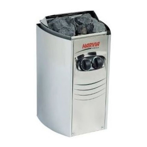
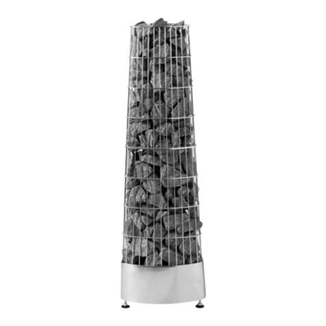
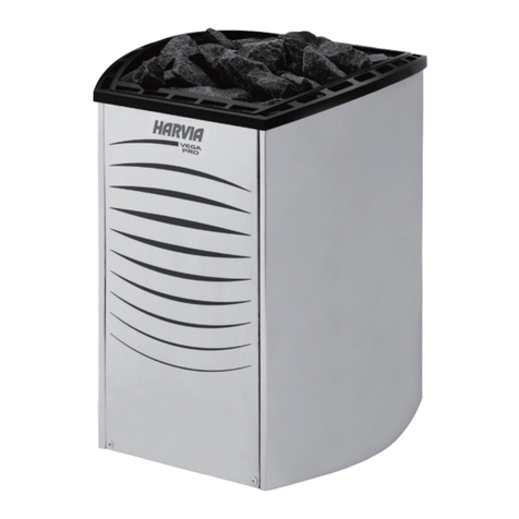
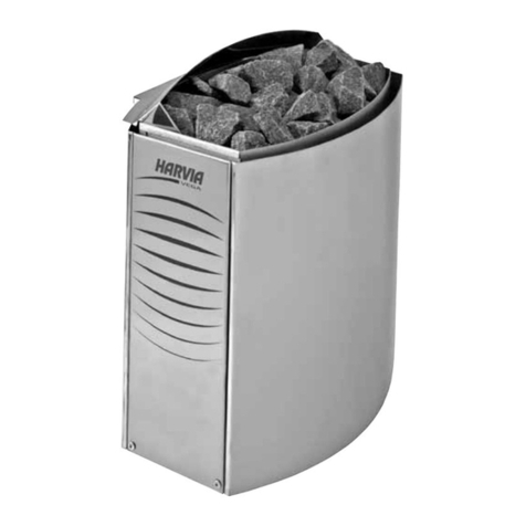
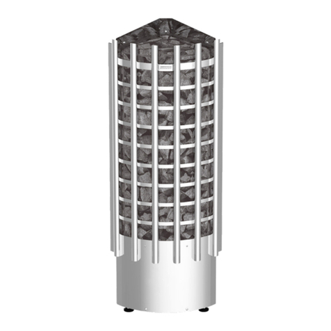
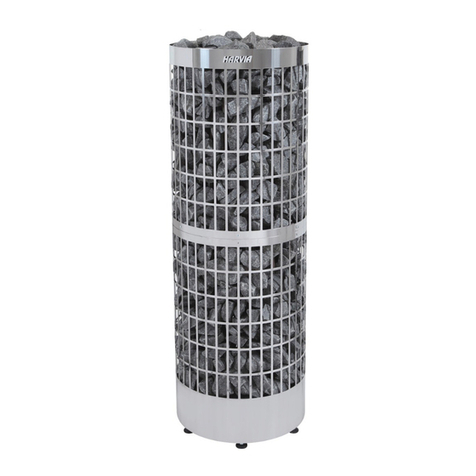
Harvia Type KIP45 User manual

Instructions for installation and use of Electric Sauna Heater
Instrucciones de instalación y uso del calentador eléctrico para sauna
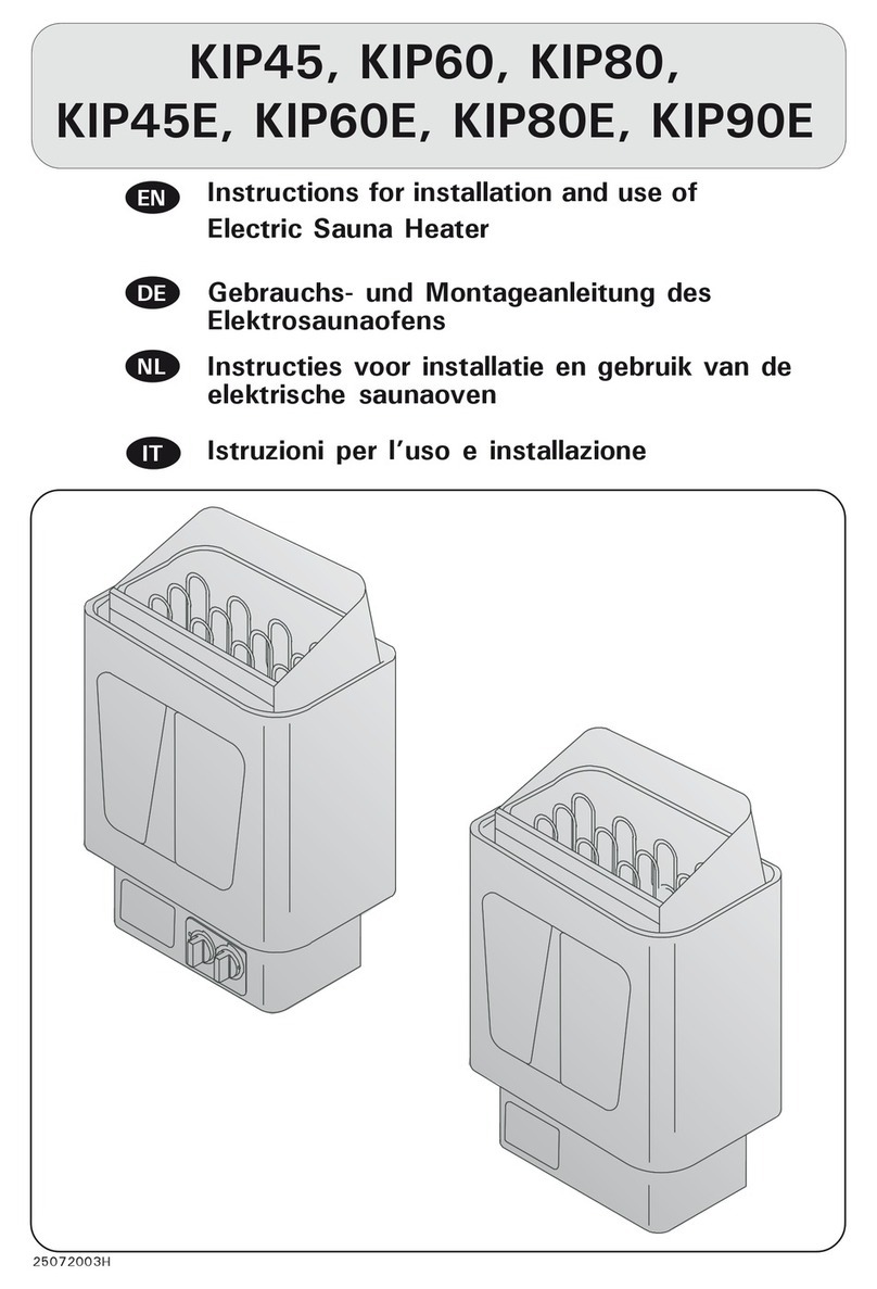
KIP45, KIP60, KIP80,
KIP45E, KIP60E, KIP80E, KIP90E
13112017/Y05-0382

These instructions for installation and use are
intended for the owner or the person in charge of
the sauna, as well as for the electrician in charge of
the electrical installation of the heater.
After completing the installation, the person in
charge of the installation should give these instruc-
tions to the owner of the sauna or to the person in
charge of its operation.
The guarantee period for heaters and control equip-
ment used in saunas by families is two (2) years.
The guarantee period for heaters and control equip-
ment used in saunas by building residents is one
(1) year.
Congratulations on your choice!
Este calentador está destinado para su uso en
una sauna doméstica. Una vez esté instalado el
calentador, se entregarán estas instrucciones de
instalación y uso al propietario de la sauna o la
persona responsable del mantenimiento de la sauna.
El periodo de garantía para calentadores y paneles
de control de uso doméstico es de dos (2) años.
El periodo de garantía para paneles de control y
calentadores de saunas del edificio es de un (1) año.
¡Felicidades por su elección!
CONTENTS
Mounting on Wall........................................................ 3
Safety Rail .................................................................4
Controls and use of the heater .....................................4
Repositioning of Thermostat and Timer
(KIP 45, KIP60, KIP80) ................................................4
Mains Connection .......................................................5
Installation of the control unit (C90, C150) and sensors
(KIP45E–KIP90E) ........................................................6
Electric heater insulation resistance ...............................7
Piling of the Sauna Stones ...........................................7
Sauna Water ..............................................................7
Use (KIP45–KIP80) .....................................................8
Timer (KIP45-KIP80)................................................... 8
Troubleshooting (KIP45–80).........................................9
Insulation and Wall Materials of the Sauna Room ............9
Blackening of the sauna walls..................................... 10
Ventilation of the Sauna Room ................................... 11
INHALT
Fijación a la pared .......................................................3
Barandilla de seguridad ................................................ 4
Paneles de control del calentador ..................................4
Traslado del termostato y el temporizador (KIP45, KIP60,
KIP80).......................................................................4
Conexión a la red eléctrica ...........................................5
Instalación del centro de control (C90, C150) y el sensor
(KIP45E–KIP90E) ........................................................6
Resistencia de aislamiento del calentador eléctrico ..........7
Apilar las piedras de la sauna........................................ 7
Agua para las piedras ..................................................7
Uso (KIP45-KIP80) ......................................................8
Temporizador (KIP45-KIP80)......................................... 8
Situación de avería (KIP45-KIP80) .................................9
Aislamiento de la sauna y materiales de la pared.............9
Oscurecimiento de las paredes de la sauna................... 10
Ventilación de la sauna .............................................. 11

EN ES
3
Fijación a la pared
Para fijarlo a la pared, consulte las instrucciones e
imágenes proporcionadas en la tabla 1. La fijación
se realiza con los tornillos entregados junto con el
calentador.
ATENCIÓN. Refuerce la pared de detrás del panel
con una tabla adicional antes de fijar el calentador
a la pared.
ATENCIÓN. El calentador deberá instalarse de tal
forma que los paneles de control estén visibles en
el lado libre del mismo y se puedan utilizar con
facilidad.
• El calentador puede instalarse en un hueco con
una altura mínima de 1 900 mm. Ver figura 2.
• Únicamente podrá instalarse un calentador
eléctrico en la sauna.
ATENCIÓN. Una protección instalada directamente
en la pared o sobre la superficie del techo puede
producir un aumento peligroso de la temperatura en
la pared y en el techo.
Figure 1. Connections and parts of the heater
Figura 1. Componentes del calentador y acoplamiento
Figure 2. Installation of the heater in a recess
Figura 2 Instalación en el hueco de la pared
1. Connection box
2. Connection lead
3. Switch box
4. Cable for control centre
(KIP 45E-90E)
4. Installation cable (KIP45-80)
5. Thermostat (KIP 45-80)
6. Timer (KIP 45-80)
7. Reset button for overheating
limiter (KIP 45-80)
1. Caja de conexiones
2. Cable de conexión
3. Caja de terminales
4. Cable para la central (KIP 45E-90E)/
Cable de instalación (KIP 45-80)
5. Termostato (KIP 45-80)
6. Temporizador (KIP 45-80)
7. Botón de retroceso del limitador de
temperatura (KIP 45-80)
Mounting on Wall
When fixing, follow the directions in table 1 and the
diagrams. Attachment is by means of the screws ac-
companying the heater. Ensure fixing behind heater
is a dequate to support heater – i.e. cross struts in
sauna panelling.
NOTE!: Reinforce the panel behind the heater with
an extra board before mounting the heater on the
wall.
NOTE!: There must be enough of working space in
front of the heater control switch.
• The heater can be installed in a recess of a
minimum height 1900 mm (see Fig. 2).
• Only one heater per sauna may be installed.
IMPORTANT: Protecting walls or ceiling with a light
material which is fixed to the surface of the wall or
ceiling may lead to a dangerous rise in temperature
in the wall or ceiling.

EN ES
4
Figure 3. Safety railing
Figura 3. Barandilla de seguridad
Figure 4. Location of the mounting rack of the heater
Figura 4. Ubicación de los tornillos de montaje del calentador
Safety Rail
We recommend if a safety rail is installed around
the heater, follow the directions given in the fig. 3.
Barandilla de seguridad
Si se instala una barandilla de seguridad alrededor
del calentador, deberán seguirse las indicaciones
de la figura 3.
Controls and use of the heater
The KIP45, KIP60, KIP80 and KIP90 heaters are
equipped with a timer and a thermostat on the lower
part of the heater.
The KIP45E, KIP60E, KIP80E and KIP90E heat-
ers must be equipped with a separate control unit
which must be installed in a dry area outside of the
sauna room.
Before you switch the heater on check always that
there aren’t any things over the heater or in the near
distance of the heater.
Repositioning of Thermostat and Timer
(KIP 45, KIP60, KIP80)
Normally the thermostat and timer are located on
the front of the heater (Fig. 3), but if desired they
may be moved to the right or left side of the heater.
Such repositioning should only be carried out by a
qualified electrician.
1. Turn the heater upside down and detach the
base plate.
2. Remove the timer (1) and thermostat (2) knobs
by pulling outwards.
3. Remove the two holding screws from the timer
and thermostat attachment plate.
4. Remove the cover plate from the side you have
chosen.
5. Replace it with the attachment plate, complete
with the timer and thermostat.
6. Push the knobs into place.
7. Attach the cover plate to the front of the
heater.
8. Check the timer and thermostat connections
and air spaces.
9. Re-attach the heater base plate.
Paneles de control del calentador
Los modelos de calentador KIP45, KIP60 y
KIP80 están equipados con un temporizador y un
termostato, que están situados en la parte baja del
calentador.
Los modelos de calentador KIP45E–KIP90E
necesitan un centro de control separado, que deberá
instalarse en un espacio seco en la parte exterior de
la sauna.
Antes de encender el calentador, siempre hay que
comprobar que no haya ningún objeto sobre él o a
poca distancia.
Traslado del termostato y el temporizador
(KIP45, KIP60, KIP80)
Por lo general, el temporizador y el termostato están
situados en la parte delantera del calentador (figura
3), pero también pueden trasladarse hacia el lado
derecho o el izquierdo del calentador. Esta tarea
únicamente podrá llevarlo a cabo un electricista
profesional autorizado.
1. De la vuelta al calentador y retire la cubierta del
fondo.
2. Separe los pomos del reloj (1) y del termostato
(2) tirando hacia fuera.
3. Retire los 2 tornillos de fijación de la placa de
fijación del reloj y el termostato.
4. Retire la cubierta del lateral.
5. Coloque la placa de fijación en el lado deseado
del calentador y fije los tornillos (no es necesario
retirar el termostato ni el reloj de la placa de
fijación).
6. Presione los pomos en su lugar.
7. Fije la cubierta en la parte delantera de la caja
de terminales.
8. Compruebe el cableado del reloj y del
termostato, así como todas las cámaras de aire.
9. Cierre la cubierta del fondo.
48
63
113
133
Type/Tipo
KIP45/
KIP45E
KIP60/
KIP60E
KIP80/
KIP80E
KIP90E
D min.
mm
20
30
30
40
Type/Tipo
KIP45/
KIP45E
KIP60/
KIP60E
KIP80/
KIP80E
KIP90E
X min.
mm
wall/pared

EN ES
5
Mains Connection
Due to thermal embrittlement, the use of PVC-in-
sulated wire as the connection cable of the heater
is forbidden.
The heater may only be connected to the electri-
cal network in accordance with the current regula-
tions by an authorised, professional electrician. The
heater is semistationarily connected to the junction
box on the sauna wall. The connection cable must
be of rubber cable type H07RN-F or its equivalent. In
the lower part of the heater there is a permanently
installed control unit (KIP45–KIP80). In addition to
a mains connector, the control centre is equipped
with extra connectors which enable the following
additional connections:
A. an indicator light above the steam room (see
the connection diagram). Cross-section of the
connection cable (see Table 1).
B. Locking of electrical heating with the heater
(see connection diagram). The control cable of
the electrical heating is connected directly to
the junction box, and from there to the terminal
strip by a rubber cable with the thickness of a
connection cable.
NOTE! The heater provides a voltage control
(230V) from the P and M connectors.
The KIP-E models require separate control centre
C90/C150 (C150VKK).
Conexión a la red eléctrica
Está prohibido el uso de cables aislados con PCV
como cables de conexión del calentador debido a
su fragilidad térmica.
La conexión del calentador a la red eléctrica podrá
efectuarla únicamente un electricista profesional
autorizado, según las normativas vigentes. El
calentador se fija de forma semipermanente
utilizando como cable de conexión un cable de
goma H07RN-F o equivalente. En la parte inferior
del calentador se encuentra un centro de control
integrado en la estructura del mismo (KIP45-KIP80).
El centro de control está equipado, además de con
el conector de red, con conectores adicionales que
posibilitan los siguientes acoplamientos:
A. luz indicadora en el exterior de la sauna (ver
plano de terminales). Sección transversal del
cable de conexión (ver tabla 1).
B. bloqueo del calentamiento eléctrico con el
calentador (ver plano de terminales). El cable
de control del control de calefacción se dirige
directamente a la caja de terminales del
calentador, desde continúa mediante el cable
de goma (tan grueso como el cable de conexión)
hasta el bloque de terminales.
¡Atención! El calentador proporciona control de
tensión (230 V) de los conectores P y M.
Los modelos KIP-E necesitan un centro de control
separado C90/C150 (C150VKK).
min. 1100
min. 100
min. 20
min. 150
KIP45E, KIP60E,
KIP80E, KIP90E
Figure 5. Safety distances and sensor positioning
(measurements in millimeters)
Figura 5. Distancias de seguridad y ubicación del sensor
(medidas en milímetros)
*) from front to upper platform / desde la superficie frontal hasta el banco superior
**) from side to wall / desde la superficie lateral hasta la pared
Table 1.
Tabla 1.
Heater
Calentador
Output
Potencia
Sauna room
Sauna
Min. distance from heater
Distancia de seguridad mínima del calentador
Connection cable/Fuses
v/Fusible
Width/anchura
41 cm
Depth/profundidad
28 cm
Height/altura
60 cm
Weight/peso
16 kg
Stones/piedras
max. 25 kg
kW Cubic. vol.
Volumen
Height
Altura
A
mm
B
mm
C
mm
To
ceiling
Hasta el
techo
To floor
Hasta
el suelo
400V3N~
mm2
Fuses
Fusible
A
min
m2
max
m2
min
mm
**) *)
KIP-E
KIP45/KIP45E 4,5 3 6 1900 35 20 35 100 1100 150 5 x 1.5 3 x 10
KIP60/KIP60E 6,0 5 8 1900 50 30 50 120 1100 150 5 x 1.5 3 x 10
KIP80/KIP80E 8,0 7 12 1900 100 30 80 150 1100 150 5 x 1.5 3 x 16
KIP90E 9,0 8 14 1900 120 40 100 150 1100 150 5 x 1.5 3 x 16

EN ES
6
Installation of the control unit (C90, C150)
and sensors (KIP45E–KIP90E)
Install the control unit in a dry place outside the
sauna room at the height of about 170 cm. The
control unit includes detailed instructions for
fastening the unit on the wall.
Install the temperature sensor on the wall of the
sauna room above the heater. It should be installed
on the lateral centre line of the heater, 100 mm
down-wards from the ceiling. See fig. 5.
Instalación del centro de control (C90, C150)
y el sensor (KIP45E–KIP90E)
El centro de control deberá instalarse en el espacio
seco del exterior de la sauna a unos 170 cm de
altura. El centro de control cuenta con instrucciones
más precisas sobre cómo fijar el centro a la pared.
El sensor de temperatura deberá instalarse en
mitad de la pared por encima del calentador, 100
mm por debajo del techo. Ver figura 5.
Figure 6. Electrical connections of heater
Figura 6. Conexiones eléctricas del calentador
400V 3N~
123
M
NL1 L2 L3 NP
a1
a1 a1
b0
b
b0
b0
bb aaa
CONTROL OF HEATING
CONTROL DE CALEFACCIÓN
KIP 45-80
CONTROL DE CALEFACCIÓN
CALENTADOR
CAJA DE
TERMINALES
CABLE DE CONEXIÓN ALIMENTACIÓN
FUSIBLE
POTENCIA/kW FUSIBLE
FUSIBLE
Blue/Azul
White/Blanco
Red/Rojo
Yellow/Amarillo
Blue/Azul
White/Blanco
Red/Rojo
Yellow/Amarillo
CONTROL DE
CALEFACCIÓN
CALENTADOR
CAJA DE TERMINALES
ALIMENTACIÓN
LUZ
FUSIBLES

EN ES
7
Electric heater insulation resistance
When performing the final inspection of the electrical
installations, a ”leakage” may be detected when
measuring the heater’s insulation resistance. The
reason for this is that the insulating material of the
heating resistors has absorbed moisture from the
air (storage/transport). After operating the heater
for a few times, the moisture will be removed from
the resistors.
Do not connect the power feed for the heater
through the RCD (residual current device)!
Piling of the Sauna Stones
The sauna stones for an electric heater should be
4–8 cm in diameter. The heater stones should be
solid blocks of stone specially intended for use in
the heater. Neither light, porous ceramic “stones“ of
the same size nor soft potstones should be used in
the heater, because they may cause the resistance
temperature to rise too high as a result of which the
resistance may be broken.
Stone dust should be washed off before piling the
stones. The stones should be piled into the stone
compartment over the grating, between the heating
elements (resistances) so that the stones support
each other. The weight of the stones should not lie
on the heating elements.
The stones should not be piled too tightly, so that
air can flow through the heater. The stones should
be fitted loosely, and not wedged between the heat-
ing elements. Very small stones should not be put
into the heater at all.
The stones should completely cover the heating
elements. However, they should not form a high pile
on the elements.
The stones disintegrate with use. Therefore, they
should be rearranged at least once a year or even
more often if the sauna is in frequent use. At the
same time, any pieces of stones should be removed
from the bottom of the heater, and disintegrated
stones should be replaced with new ones.
The guarantee does not cover any faults caused
by the use of stones not recommended by the plant.
Neither does the guarantee cover any faults caused
by disintegrated or too small stones blocking the
heater ventilation.
No such objects or devices should be placed inside
the heater stone space or near the heater that could
change the amount or direction of the air flowing
through the heater, thus causing the resistance tem-
perature to rise too high, which may set the wall
surfaces on fire!
Sauna Water
The water to be thrown on the heated stones should
meet the requirements of clean household water.
The factors essentially affecting the quality of water
Resistencia de aislamiento del calentador eléctrico
En la inspección final de la instalación eléctrica, es
posible que la medición de resistencia de aislamiento
del calentador indique «pérdida»: esto se debe a que
la humedad del aire ha sido absorbida por el material
aislante de la resistencia térmica (almacenamiento/
transporte). La humedad desaparecerá de la
resistencia tras un par de sesiones de calentamiento.
¡No conecte el suministro eléctrico al calentador a
través de un dispositivo de corriente residual!
Apilar las piedras de la sauna
El tamaño de piedra adecuado para un calentador
eléctrico es un diámetro de 5-10 cm. Deberán
utilizarse piedras para sauna específicas, masivas y
de marca conocida. Está prohibido utilizar «piedras»
cerámicas ligeras, porosas y del mismo tamaño, ya
que pueden producir un calentamiento excesivo y
rotura en las resistencias. Tampoco está permitido
utilizar piedras blandas de esteatita como piedras
de la sauna.
Es conveniente limpiar el polvo de piedra de las
piedras antes de apilarlas. Las piedras se apilan en el
compartimento para piedras del calentador encima de
la parrilla, entre los elementos calefactores, de modo
que se sostengan unas a otras. No está permitido
apoyar el peso de las piedras contra los elementos
calefactores.
Las piedras no deberán apilarse de forma demasiado
compacta, para no impedir la circulación del aire a
través del calentador. Tampoco deberán colocarse en
forma de cuña entre los elementos calefactores, sino
de forma holgada. En ningún caso deberán utilizarse
piedras demasiado pequeñas. Las piedras deberán
cubrir los elementos calefactores por completo.
No deberán construirse montones altos de piedras
encima de los radiadores.
Con el uso, las piedras se deterioran, por lo que
deberán apilarse de nuevo al menos una vez al año, y
con más frecuencia en caso de uso habitual. Además,
deberán retirarse los restos de piedra acumulados en
la parte inferior del calentador y las piedras rotas
deberán reemplazarse.
La garantía no cubre los fallos causados por usos
de las piedras diferentes al recomendado por el
fabricante. La garantía tampoco cubre los fallos
causados por trozos de piedra o piedras demasiado
pequeñas que bloqueen la circulación del aire del
calentador.
En el compartimento para piedras del calentador y
en las inmediaciones del mismo no podrá colocarse
ningún objeto o dispositivo que modifique la cantidad
de aire que pasa a través del calentador la dirección
del mismo, de modo que produzcan un excesivo
calentamiento de los elementos calefactores y
peligro de incendio en la superficie de las paredes.
Agua para las piedras
Deberá utilizarse agua que cumpla con las exigencias
de calidad de agua para uso doméstico.
Los factores que influyen en la calidad del agua son:

EN ES
8
include the following:
• humuos content (colour, taste, precipitates);
recommended content less than 12 mg/litre.
• iron content (colour, smell, taste, precipitates);
recommended content less than 0,2 mg/litre.
• hardness - the most important substances
are manganese (Mn) and calcium (Ca);
recommended content of manganese 0,05 mg/
litre, calcium less than 100 mg/litre.
Calcareous water leaves a white, sticky layer on
the stones and metal surfaces of the heater. Calci-
fication of the stones deteriorates the heating prop-
erties.
Ferrous water leaves a rusty layer on the surface
of the heater and elements, and causes corrosion.
The use of humous, chlorinated water and sea-
water is forbidden.
Only special perfumes designed for sauna water
may be used. Follow the instructions given on the
package.
Use (KIP45–KIP80)
Temperature control: The desired sauna temperature
is set by turning the knob on the heater tempera-
ture control. The sauna will heat up to the required
temperature within about one hour, depending on
the size, construction and thermal insulation of the
sauna. The thermostat will keep the sauna at the
set temperature.
The heater thermostat also protects the heat-
ing elements against overheating. If the stones are
packed too tightly air will not circulate properly in-
side the unit. The thermostat will cut the power off
to prevent overheating, with the consequense that
the sauna will heat up abnormally slowly.
Temperature limiting: If for some reason the wooden
components of the sauna become abnormally hot,
the temperature limit cut-out will switch the heater
completely. When the temperature has reached nor-
mal level, the limit cut-out can be manually reset us-
ing the button located next to the heater thermostat
knob. (See figure 1).
Timer (KIP45-KIP80)
The heater is switched on by using the timer switch.
The timer has two scales: the first one (with larger
figures) is the ”instantly on” section; that is, the
heater is on for a selected period of time (0–4 hours).
The other section is the so called ”pre-set section”
(1–8 hours), which is used to start the heater after
a certain time. The heater starts when the timer has
turned the switch back to the ”instantly on” section,
that is, at number four (4). After this, the heater will
be on for about 4 hours, unless the switch is turned
to zero before that. At zero (0), the supply to the
elements is cut off and the heater is switched off.
• contenido de humus (color, sabor, sedimentos);
recomendación por debajo de 12 m/l.
• contenido de hierro (color, sabor, sedimentos);
recomendación por debajo de 0,2 mg/l.
• dureza; las sustancias más importantes
son manganeso (Mn) y calcio (Ca) o cal; la
recomendación de manganeso es por debajo
de 0,05 mg/l, y la de calcio, por debajo de 100
mg/l.
El agua caliza deja una capa blanca pastosa
en las piedras del calentador y en las superficies
metálicas. La calcificación de las piedras debilita las
propiedades de la sauna.
El agua ferruginosa deja una capa de óxido en
la superficie del calentador y de los elementos
calefactores que puede producir erosión.
Está prohibido el uso de aguas cloradas o que
contengan humus y agua de mar.
Solamente se podrán utilizar fragancias destinadas
al agua de la sauna. Siga las instrucciones del
envase.
Uso (KIP45-KIP80)
Ajuste de temperatura: Mediante los reguladores de
temperatura se puede elegir la temperatura deseada
de la sauna. La sauna alcanzará la temperatura
deseada aproximadamente en una hora, dependiendo
del tamaño, la estructura y el aislamiento térmico. El
termostato se encargará de que la temperatura de
la sauna permanezca al nivel deseado.
El termostato del calentador también protege los
elementos calefactores del sobrecalentamiento. Si
las piedras del compartimento están demasiado
apretadas, es posible que impidan la circulación
del aire en el calentador y el calentamiento de la
sauna se ralentice cuando el termostato interrumpa
la corriente hacia la resistencia sobrecalentada.
Limitación de temperatura: En caso de que, debido
a un fallo, las partes de madera de la sauna alcancen
una temperatura peligrosamente alta, el limitador
de temperatura interrumpirá toda la potencia del
calentador. Una vez la temperatura haya vuelto a
descender a un valor habitual, podrá conectarse de
nuevo la corriente pulsando el botón de retroceso
del limitador de temperatura, que se encuentra al
lado del regulador de temperatura del calentador.
Antes de esto, deberá aclararse el motivo del fallo.
Ver figura 1.
Temporizador (KIP45-KIP80)
El temporizador 8-4 h, que funciona como interruptor
principal del calentador, corta automáticamente la
corriente cuando haya pasado el tiempo deseado. En
el reloj de preselección se puede escoger un tiempo
de encendido programado de entre 1 y 8 horas, y el
tiempo de funcionamiento máximo siempre es de 4
horas. El tiempo de encendido programado se puede
utilizar cuando se desee que la sauna se caliente
transcurrido cierto tiempo.
EN ES
9
Example 1. You want to go jogging and have a sauna
bath after that. The estimated duration of your run
is 5 hours. Turn the timer clockwise over the scale
0–4 to the pre-set section (scale 1–8) at number 4.
The timer will start, and after four hours, the heat-
er will come on. Because it takes about one hour for
the sauna to be heated, it will be warm and ready
for bathing after about 5 hours, that is, when you
come back from your run.
Example 2. If you want to bathe ”immediately” and
thus do not want to use the pre-set timing, the timer
must be set to the desired point in the section 0–4.
Then, the heater will be switched immediately on
and the sauna will be ready for bathing after about
one hour.
Switch the heater off immediately after bathing
and check that the sauna stones are dry. Some-
times it may be advisable to leave the heater on
for a while to let the wooden parts of the sauna dry
properly.
NOTE! It is absolutely necessary to check that the
timer has cut off the supply of the elements after
the set time.
Troubleshooting (KIP45–80)
If the heater does not heat, check the following
points:
• the electricity has been switched on
• the thermostat shows a higher figure than the
temperature of the sauna.
• the fuses to the heater are in good condition.
• the temperature guard has not gone off. The
timer sound is heard but the elements are not
heated.
• the timer has been switched to a section where
the heater should be heated (0–4).
Insulation and Wall Materials of the Sauna Room
In an electrically heated sauna, all the massive wall
surfaces which store plenty of heat (such as bricks,
glass blocks, plaster etc.), must be sufficiently insu-
lated in order to keep the heater output at a reason-
ably low level.
A wall and ceiling construction can be considered
to have efficient thermal insulation if:
• The thickness of carefully fitted insulating wool
inside the house is 100 mm (minimum 50 mm)
• The moisture protection consists of e.g. alu-
minium paper with tightly taped edges. The
paper must be fitted so that the glossy side is
towards the inside of the sauna
• There is a 10 mm vent gap between the moisture
protection and panel boards (recommendation)
Ejemplo 1. Va a ir a esquiar y quiere usar la sauna
cuando vuelva. El tiempo estimado de esquí es
de 5 horas. El temporizador del calentador se gira
en el sentido de las agujas del reloj desde el área
de funcionamiento (escala 1-4) hasta el área de
preselección (escala 1-8), hacia la posición 4. Ahora
el reloj empezará a funcionar y, transcurridas cuatro
horas, la corriente se conectará al calentador y este
empezará a calentar. Debido a que el tiempo de
calentamiento de la sauna es de aprox. 1 hora, la
sauna estará caliente y lista para su uso después
de unas 5 horas, cuando vuelva de su excursión
de esquí. Una vez el temporizador haya pasado del
área de preselección al área de funcionamiento, el
calentador estará encendido durante un máximo
de 4 horas, después de las cuales la corriente se
interrumpirá automáticamente. En caso de que
quiera apagar la sauna antes, gire el temporizador
hasta la posición 0.
Ejemplo 2. Si quiere usar la sauna inmediatamente y
no quiere utilizar la preselección, gire el temporizador
en el área de funcionamiento hasta la posición
deseada entre 1 y 4, de modo que la corriente se
conecte de forma inmediata y el calentador empiece
a calentar.
¡ATENCIÓN! Si, después de usar la sauna, deja el
calentador encendido para secar la sauna, deberá
asegurarse de que el temporizador ha interrumpido
la corriente del calentador transcurrido el tiempo
determinado.
Situación de avería (KIP45-KIP80)
En caso de que el calentador no caliente, deberá
comprobar lo siguiente:
• que la corriente está conectada
• que el termostato esté girado hacia el valor más
alto de temperatura de la sauna
• que los fusibles del calentador estén intactos.
• que no se haya disparado el limitador de
temperatura. En ese caso, se oye el ruido del reloj,
pero los elementos calefactores no se calientan.
• que el regulador del temporizador esté girado
hacia el intervalo en el que el calentador se
calienta (0-4).
Aislamiento de la sauna y materiales de la pared
En una sauna eléctrica, todas las superficies masivas
de pared que acumulan mucha temperatura (ladrillo,
bloques de vidrio, yeso y equivalentes) deberán
aislarse de forma suficiente, en caso de que desee
mantenerse la potencia del calentador a un nivel
relativamente bajo.
Se puede considerar que la construcción de las
paredes y el techo de una sauna tienen buen
aislamiento térmico si:
• el grosor de la lana de aislamiento colocada
cuidadosamente en el interior del edificio es de
100 mm (al menos 50 mm)
• la impermeabilización de la construcción es de,
por ejemplo, papel de aluminio, cuyas juntas se
han sellado con cinta y el papel se ha instalado

EN ES
10
• The inside is covered by 12–16 mm thick
panelling
• There is a vent gap of a few millimetres at the
top of the wall covering at the edge of the ceil-
ing panelling
When aiming at a reasonable heater output, it may
be advisable to lower the ceiling of the sauna (nor-
mally 2100–2300 mm, minimum height 1900 mm).
As a result, the volume of the sauna is decreased,
and a smaller heater output may be sufficient. The
ceiling can be lowered so that the ceiling joists are
fixed at a suitable height. The spaces between the
joists are insulated (minimum insulation 100 mm)
and surfaced as described above.
Because heat goes upwards, a maximum distance
of 1100–1200 mm is recommended between the
bench and ceiling.
NOTE! Consult fire-extinguishing authorities to
find out which part of the fireproof wall may be
insulated. Do not insulate air chimneys.
NOTE! The protection of the walls or ceiling with
heat protection, such as mineral board fitted directly
on the wall or ceiling, may cause the temperature
of the wall and ceiling materials to rise dangerously
high.
Blackening of the sauna walls
Wooden material in a sauna, such as panels, black-
ens with age. The blackening process is sped up by
sunlight and the heat from the heater. If the wall
surfaces have been processed with protective panel
agents, the blackening of the surface of the wall
above the heater can be seen quite quickly depend-
ing on the protective agent used. The blackening is
due to the fact that the protective agents have less
resistance to heat than unprocessed wood do. This
has been proven in practical tests.
The micronic mineral aggregate that crumbles
from the stones on the heater may blacken the wall
surface near the heater.
When following the manufacturer’s approved
guidelines in the installation of the sauna heater, the
heater will not heat up enough to endanger the flam-
mable material in the sauna room. The maximum
temperature allowed in the wall and ceiling surfaces
of the sauna room is +140 degrees Celsius.
Sauna heaters equipped with CE signs meet all
of the regulations for sauna installations. Proper
authorities monitor that the regulations are being
followed.
de modo que la parte brillante dé hacia el
interior de la sauna
• entre la impermeabilización y el panel haya
(recomendado) una abertura de ventilación de
unos 10 mm
• el revestimiento interno sea un panel pequeño,
de un grosor aproximado de 12-16 mm
• en la parte superior de los revestimientos de
pared, en el borde de los paneles del techo, hay
una abertura de ventilación de varios mm
Para conseguir una potencia del calentador
adecuada, puede ser justificable bajar la altura del
techo de la sauna (normalmente, 2 100-2 300 mm,
altura mínima de la sauna 1 900 mm), de modo
que el volumen de la sauna disminuya y se pueda
elegir una menor potencia del calentador. La bajada
del techo se realizará de tal forma que el envigado
se dimensione a una altura adecuada. El hueco
entre las vigas deberá aislarse (aislamiento de al
menos 100 mm) y revestirse del modo mencionado
anteriormente.
Debido a que el calor tiende a ir hacia arriba, se
recomienda que la altura entre el banco y el techo
no supere los 1 100-1 200 mm.
¡ATENCIÓN! Deberá acordar con las autoridades
antiincendios qué partes del muro cortafuegos puede
aislar. ¡No está permitido aislar las salidas de humo
activas!
¡ATENCIÓN! Una protección instalada directamente
en la pared o sobre la superficie del techo, por ejemplo
una chapa mineral, puede producir un aumento
peligroso de la temperatura en los materiales de la
pared y el techo.
Oscurecimiento de las paredes de la sauna
Los materiales de madera de la sauna, como los
paneles, se oscurecen con el paso del tiempo. Al
oscurecimiento contribuyen también la luz del sol y
el calor del calentador. Si la superficie de las paredes
ha sido tratada con un protector de paneles, el
oscurecimiento de la superficie de la pared en la parte
superior del calentador será considerablemente más
rápida, dependiendo del agente protector utilizado.
El oscurecimiento se debe a que el agente protector
tiene una resistencia al calor menor que la madera
sin tratar. Este hecho se ha comprobado en prueba
práctica. Incluso el material rocoso de grano fino que
se suelta de las rocas de la sauna y se eleva con
las corrientes de aire puede oscurecer la superficie
de las paredes en las proximidades del calentador.
Si se siguen las instrucciones aprobadas del
fabricante en la instalación del calentador, este no
calentará los materiales combustibles de la sauna a
una temperatura peligrosa. La temperatura máxima
permitida en las superficies de las paredes y el techo
de la sauna es de +140 grados.
Los calentadores de sauna que cuentan con
la marca CE cumplen todas las disposiciones
establecidas para la instalación de saunas.

EN ES
11
Ventilation of the Sauna Room
Sufficient ventilation is extremely important for the
sauna. The air in the sauna room should be changed
six times per hour. The fresh air pipe should come
directly from outside. According to the newest re-
search results, the pipe should be located at a mini-
mum height of 50 cm above the heater. The pipe
diameter should be about 5–10 cm.
Exhaust air should be led from the lower part of
the sauna directly into the air chimney, or, by using
an exhaust pipe starting near the floor level, into
a vent in the upper part of the sauna. Exhaust air
can also be led out through an exhaust air vent in
the washing room through a 5 cm opening under
the sauna door. The exhaust air of the sauna room
should be taken from as far from the heater as pos-
sible, but near the floor level. The crosscut area of
the exhaust air vent should be twice that of the
supply air pipe.
For the above-mentioned system, mechanical ven-
tilation is necessary.
If the heater is mounted in a ready-made sauna,
the instructions of the sauna manufacturer should
be followed when arranging ventilation.
The series of pictures shows examples of ventila-
tion systems for a sauna room. See fig. 7.
Ventilación de la sauna
Es muy importante que la sauna cuente con una
ventilación eficaz. El aire de la sauna deberá
cambiarse seis veces por hora. Conviene colocar el
canalizador de aire fresco por encima del calentador,
al menos a 500mm de altura del mismo. El diámetro
del tubo deberá ser de entre 50 y 100mm.
El aire de extracción de la sauna debería extraerse
lo más lejos posible del calentador, pero cerca del
suelo. La sección transversal de la abertura del aire
de extracción deberá ser dos veces más grande que
el canalizador de aire fresco.
El aire de extracción deberá conducirse
directamente hacia la salida de humo, o a través
del tubo de extracción que empiece cerca del suelo
hasta la válvula situada en la parte superior de la
sauna. El aire de extracción también podrá dirigirse
por debajo de la puerta hacia el cuarto de la ducha, si
este tiene una válvula de aire de extracción. Debajo
de la puerta deberá haber una rendija de unos 100-
150 mm.
La ventilación descrita anteriormente funcionará
si se lleva a cabo de forma mecánica.
En caso de que se instale el calentador en una
sauna montada de fábrica, deberán observarse las
instrucciones del fabricante.
En las imágenes hay ejemplos de distintas
soluciones de ventilación para saunas. Ver figura 7
1. Air supply vent.
2. Optional air supply vent, if mechanical exhaust ventila-
tion is used. The opening is located 50 cm above the
heater.
3. Exhaust air vent.
4. Possible drying valve, which is closed during heating and
bathing. The sauna can also be dried by leaving the door
open after bathing.
5. If there is an exhaust vent in the washing room only,
there should be a minimum 10 centimetre opening
under the sauna room door. Mechanical ventilation is
recommended.
1. Ubicación de la abertura de suministro de aire.
2. Ventilación de suministro de aire opcional, si la
ventilación de escape mecánica es usado. La apertura se
encuentra a 50 cm por encima del calentador.
3. Abertura de extracción de aire.
4. Posible válvula de secado, que está cerrada durante el
tiempo de calentamiento y de sauna. La sauna también
puede secarse dejando la puerta abierta después de
usarla.
5. Si la abertura de extracción de aire solo está en la parte
del cuarto de la ducha, la ranura debajo de la puerta de la
sauna deberá ser de al menos 100 mm. Es recomendable
una ventilación mecánica.
Figure 7. Ventilation of the sauna room
Figura 7. Ventilación de la sauna

Other manuals for Type KIP45
4
This manual suits for next models
6
Table of contents
Other Harvia Electric Heater manuals

Harvia
Harvia Spirit HSPE604M User manual

Harvia
Harvia V45XE User manual

Harvia
Harvia HPC1104XE User manual

Harvia
Harvia K13 User manual

Harvia
Harvia K10.5GS User manual

Harvia
Harvia Unio User manual

Harvia
Harvia PC70EE User manual

Harvia
Harvia PI Series User manual

Harvia
Harvia HH6 User manual

Harvia
Harvia Spirit Owner's manual

Harvia
Harvia NK36E User manual

Harvia
Harvia BC23 User manual

Harvia
Harvia GL70 Guide

Harvia
Harvia HPOE704 User manual

Harvia
Harvia TRT70EE User manual

Harvia
Harvia KIP-30-B1 User manual

Harvia
Harvia PO11 User manual

Harvia
Harvia MDA165/200G User manual

Harvia
Harvia PC70XE User manual

Harvia
Harvia PI Series User manual